Contents
- Real-Time Traffic over WLAN Quality of Service
- Quality of Service architectural overview
- QoS importance to Real-Time Traffic over WLAN
- Wireless QoS deployment schemes
- Wi-Fi multimedia
- Client connection types
- QoS advanced features for WLAN infrastructure
- IEEE 802.11e, IEEE 802.1P, and DSCP mapping
- Wireless QoS deployment guidelines
Real-Time Traffic over WLAN Quality of Service
This chapter describes quality of service (QoS) in Real-Time Traffic WLAN implementations. It describes WLAN QoS in general and does not discuss security and segmentation in depth, though QoS is a part of these components. It also provides information about Cisco Centralized WLAN architecture features.
- Quality of Service architectural overview
- QoS importance to Real-Time Traffic over WLAN
- Wireless QoS deployment schemes
- Wi-Fi multimedia
- Client connection types
- QoS advanced features for WLAN infrastructure
- IEEE 802.11e, IEEE 802.1P, and DSCP mapping
- Wireless QoS deployment guidelines
Quality of Service architectural overview
QoS refers to the capability of a network to provide differentiated service to selected network traffic over various network technologies. QoS technology provides the following benefits:
- Provides building blocks for business multimedia and voice applications that are used in campus, WAN, and service provider networks.
- Allows network managers to establish service-level agreements (SLAs) with network users.
- Enables network resources to be shared more efficiently and expedites the handling of mission-critical applications.
- Manages time-sensitive multimedia and voice application traffic to ensure that this traffic receives higher priority, greater bandwidth, and less delay than best-effort data traffic.
- Application visibility and control for WLAN
With QoS, bandwidth can be managed more efficiently across LANs, including WLANs and WANs. QoS provides enhanced and reliable network service by:QoS importance to Real-Time Traffic over WLAN
The WLAN used for both packet transmission and reception is unlicensed, unprotected, and unshielded. Multiple specifications, protocols, and devices take advantage of unlicensed and no-cost media (radio frequencies) by a WLAN. Consider the following example.
A tablet user in a business office is using Bluetooth to print a document. Another laptop user in the same office is using 2.4 GHz frequency Wi-Fi for a video conference and presentation. A new guest user, in the lobby, is using a smartphone to check email through the guest VLAN on the Wi-Fi network. The Wi-Fi network must prioritize the 2.4 GHz radio frequency shared by the three devices, to give real-time video conference application priority over the guest smartphone user and tablet user. In addition, the Wi-Fi network must also address the tablet Bluetooth transmission interference.
WLAN queue and schedule mechanism
802.11 WLAN has its own queue and schedule mechanism, which is divided into four access categories (ACs). These four Wi-Fi AC queues provide differentiated access to the Wi-Fi channel. The four Wi-Fi QoS categories also align to the 802.1P access categories. Because Wi-Fi is designed to carry multiple Layer 3 protocols, specific implementations typically map the Differentiated Services Code Point (DSCP) values in the IP header of the packet to be sent by the Wi-Fi radio into one of the ACs.
The voice packets are placed in queue with the highest priority for WLAN depending on the DSCP value or IP QoS value of voice packets in the phone call, known as voice access category. In Cisco wireless controllers, voice packets also map to the Platinum QoS profile. Voice and video packets from a voice or video call have quicker and more frequent access to the Wi-Fi channel than data packets. There will be packet collisions between the phone call and data application, because Wi-Fi is a shared medium. Wi-Fi QoS prioritizes the backoff and packet retry logic for both real-time voice and video traffic and data traffic, based on configuration values in the WLAN enhanced distributed coordination function (EDCF).
The Bluetooth (BT) radio, as well as the Wi-Fi radios in the laptop, smartphone, tablet, and access point are all half-duplex. Therefore, when each of these four radios transmit a packet, they all change to a receive-packet state, waiting for packet that acknowledges that the packet they sent was received correctly. This is where the 802.11e specification of 2005 for Wi-Fi plays an important role with QoS channel prioritization. 802.11 WLAN protocols have at their basic media access logic a process called carrier sense multiple access with collision avoidance (CSMA/CA). The Wi-Fi units wait in receive packet mode for the absence of a carrier (radio frequency) before they transmit a packet. Therefore, all Wi-Fi devices in the vicinity of a BT radio wait for the BT radio to quit transmitting before they can transmit. The dominant BT data rate used in smartphones to earbuds is 2 Mbps. Therefore, a G.711 voice packet of 256 bytes sent from a BT radio is going to delay the Wi-Fi devices on the same 2.4 GHz frequency for over 1100 microseconds, while the same G.711 voice packet on 802.11n Wi-Fi takes about 50 microseconds to send.
The Cisco CleanAir technology defines and locates the general area where BT and other interferers exist and helps avoid them. But, BT uses the entire 2.4 GHz frequency allocation that Wi-Fi uses. Therefore, it is a protocol that cannot be avoided by all the Wi-Fi channels thus making the QoS mechanism the best solution for mitigating BT interference.
The Wi-Fi QoS protocol is known as Wi-Fi Multimedia (WMM). WMM is a subset of the 802.11e specification. The 802.11e specification was approved in 2005; however, it was extensively used by Wi-Fi Alliance and Microsoft even before 2005. With the 802.11e specification, devices required new drivers to become Wi-Fi QoS capable with no hardware changes. The legacy devices without QoS have specialized hardware designs with limited firmware memory.
With the approved Wi-Fi QoS protocol in 2005, the need for Wi-Fi channel bandwidth has grown immensely along with continuous improvement in quality, range, and speed. Thus, it is now possible for a site that was dependent on the legacy data rates of 1, 2, 5.5 and 11 Mbps to disable those rates completely with valid reasons.
802.11 WLAN channel bandwidth is a managed media resource. The Wi-Fi channel is the first hop upstream and the last hop downstream. Because this medium is open to radio interference and non-Wi-Fi protocols, it is the media hop that influences the performance of the applications running on the Wi-Fi devices. When considering voice and video applications like Cisco Jabber, the Wi-Fi channel is the medium most likely to have a negative impact on the mean opinion score (MOS) value of a call. Therefore, bandwidth must be managed to insure that applications can perform to meet the expectations of the users.
Removing 802.11b data rates can double bandwidth in a 2.4 GHz Wi-Fi channel. The sites that require 802.11b and have performance issues must consider whether to disable the data rates of 1, 2 and 5.5. A required data rate of 11 Mbps provides all the support required for legacy and special application devices. Cisco APs with beam forming technology use the orthogonal frequency-division multiplexing (OFDM) modulation to further enhance client performance and Wi-Fi channel bandwidth. The OFDM radio modulation was introduced to Wi-Fi in 1999 in the 5 GHz bands with the 802.11a specification. OFDM came into practice for 2.4 GHz with the 802.11g specification that was approved in 2003. With over 10 years of use and technology development, 2.4 GHz OFDM modulation eliminates the high cost of maintaining backwards compatibility for 802.11b technology.
The following four WMM QoS priority options, also known as QoS profiles, are used for WLAN/SSID configuration with Cisco Wireless LAN Controllers: These WMM options set the priority limit of traffic between the AP, the wireless LAN controller upstream, and the priority limit from the wireless controller to the Wi-Fi endpoint downstream.For example, a voice packet with a DSCP voice priority value in a WLAN/SSID configuration of Silver with best effort has an IP Control and Provisioning of Wireless Access Points (CAPWAP) wrapper header DSCP value of best effort. A data packet with a DSCP value of zero in a WLAN/SSID with a Platinum voice configuration maintains a best effort priority, while a voice packet in the same WLAN/SSID maintains its voice priority.
The Cisco WLAN Controller (WLC) provides several methods to upgrade video or voice packets that originate with a DSCP value less than a video or voice value to be upgraded to the highest priority that is configured for the WLAN/SSID, for example, a desktop client like Cisco Jabber on a Windows computer. While the call control server can be configured to have the software application mark audio and video packets with appropriate DSCP values, the Windows operating system may be in a default configuration that does not allow QoS marking. Therefore, the audio and video is sent to the AP with best effort Wi-Fi media access. But upstream from the AP, those packets can be inspected using deep packet snooping, resulting in subsequent packet marking upgrades.
The Cisco Jabber application with Cisco Enterprise Medianet has the advantage of the peer relationship with Medianet switches. A Medianet-aware client application has built-in intelligence to address the unique challenges of video and rich media by providing:The first hop to the network from a Wi-Fi client is the shared Wi-Fi channel. The client device access to the Wi-Fi channel is the most influential aspect in the overall user acceptance of performance.
The WLAN configuration holds no control on the marking of the packets from the endpoint Wi-Fi client to the AP or vice-versa. The application DSCP markings, operating system, and the WMM driver control the marking values and the AC queues. Therefore, is it most important that you manage these three aspects of the source client. The delay incurred on the first hop because of the lack of QoS on the endpoint Wi-Fi client cannot be made up by deep packet inspection and remarking logic in the AP or upstream from the AP.
Wireless QoS deployment schemes
Cisco Unified Wireless products support WMM, a QoS system based on IEEE 802.11e published by the Wi-Fi Alliance, WMM Power Save, and Admission Control.
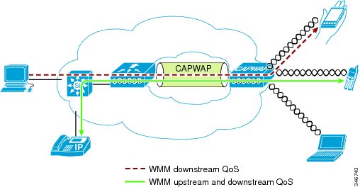
The following figure shows an example of deployment of wireless QoS based on the Cisco Unified Wireless technology features.
QoS parameters
QoS is the measure of performance for a transmission system that reflects its transmission quality and service availability. Service availability is a crucial element of QoS. Before you implement QoS successfully, the network infrastructure must be highly available. The network transmission quality is determined by latency, jitter, and loss, as described in the following table.Upstream and downstream QoS
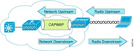
The following figure defines radio upstream and downstream and includes the following:
- Radio downstream QoS: Traffic leaving the AP and traveling to the WLAN clients. Radio downstream QoS is the most common deployment. The radio client upstream QoS depends on the client implementation.
- Radio upstream QoS: Traffic leaving the WLAN clients and traveling to the AP. WMM provides upstream QoS for WLAN clients that support WMM.
- Network downstream: Traffic leaving the WLC and traveling to the AP. QoS can be applied at this point to prioritize and rate-limit traffic to the AP. Configuration of Ethernet downstream QoS is not covered in this chapter.
- Network upstream: Traffic leaving the AP and traveling to the WLC. The AP classifies traffic from the AP to the upstream network according to the traffic classification rules of the AP.
QoS/WMM and Wi-Fi channel/network performance
The application of QoS features cannot be detected on a lightly loaded network. QoS features begin to apply on the application performance as the load on the network increases. If you can measure latency, jitter, and loss when the medium is lightly loaded, it indicates either a system fault, poor network design, or that the latency, jitter, and loss requirements of the application are not a good match for the network.
QoS functions to keep latency, jitter, and loss for selected traffic types within acceptable boundaries. When you provide only radio downstream QoS from the AP, radio upstream client traffic is treated as best-effort. A client must compete with other clients for upstream transmission, as well as compete with best-effort transmission from the AP. At certain load conditions, a client experiences upstream congestion, and the performance of QoS-sensitive applications becomes unacceptable, despite the QoS features on the AP. The upstream and downstream QoS can be operated either by using WMM on both the AP and WLAN client, or by using WMM and a client proprietary implementation.
Note
Benefits to client traffic from a WLAN client with WMM support are not direct. The applications that look for benefits of WMM assign a priority classification to their traffic, and the operating system passes this classification to the WLAN interface. In purpose-built devices, such as wireless voice handsets, the implementation is integrated as part of the design. However, if you implement it on a general-purpose platform, such as a personal computer (PC), you must first implement application traffic classification and OS support to achieve better results.
Wi-Fi multimedia
Wi-Fi MultiMedia (WMM), formerly known as Wireless Multimedia Extensions, refers to QoS over Wi-Fi. QoS enables Wi-Fi access points to prioritize traffic and optimize the way shared network resources are allocated among different applications.
This section describes the following three considerations for WMM implementation:
WMM access
WMM is a Wi-Fi Alliance certification of support for a set of features from an 802.11e draft. This certification is for both clients and APs, and certifies the operation of WMM. WMM is primarily the implementation of enhanced distributed coordination function (EDCF) component of 802.11e. Additional Wi-Fi certifications are planned to address other components of the 802.11e.
WMM classification
WMM uses the 802.1P classification scheme developed by the IEEE (which is now a part of the 802.1D specification).
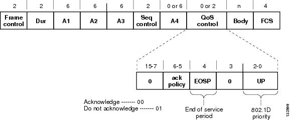
This classification scheme has eight priorities, which WMM maps to four access categories: AC_BK, AC_BE, AC_VI, and AC_VO. These access categories map to the four queues that are required by a WMM device, as shown in the following table.The following figure shows the WMM data frame format.
Even though WMM maps the eight 802.1P classifications to four access categories, the 802.1D classification is sent in the frame.
Note
The WMM and IEEE 802.11e classifications are different from the classifications that are recommended and used in the Cisco network, which are based on IETF recommendations. The primary difference in classification is the change of voice and video traffic to 5 and 4, respectively. This allows the 6 classification to be used for Layer 3 network control. To be compliant with both standards, the Cisco Unified Wireless solution performs a conversion between the various classification standards when the traffic crosses the wireless-wired boundary.
WMM queues
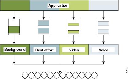
The following figure shows the queuing that is performed on a WMM client or AP.
There are four separate queues, one for each of the access categories. Each of these queues compete for the wireless channel, with each of the queues using different interframe space, contention window (CW) minumum (CWmin) and contention window maximum (CWmax) values as defined by EDCF. If more than one frame from different access categories collide internally, the frame with the higher priority is sent, and the lower priority frame adjusts its backoff parameters as though it had collided with a frame external to the queuing mechanism.
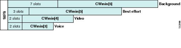
The following figure shows the principle behind EDCF where different interframe spacing and CWmin and CwMax values (for clarity, CwMax is not shown) are applied per traffic classification.
Different traffic types can wait different interface spaces before counting down their random backoff, and the CW value used to generate the random backoff number also depends on the traffic classification. For example, the CWmin[3] for voice traffic is 23-1, and CWmin[5] for best effort traffic is 25-1. High priority traffic has a small interframe space and a small CWmin value, giving a short random backoff, whereas best effort traffic has a longer interframe space and large CWmin value, that, on average, gives a large random backoff number.
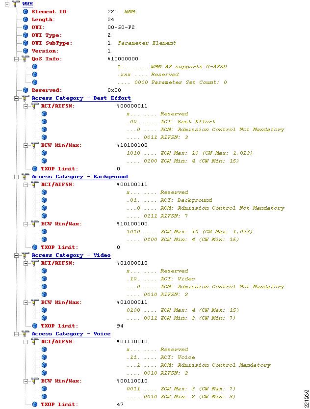
The following figure shows the WMM information in a probe response.
The elements on the client not only contain WMM AC information, but also define which WMM categories require admission control. For example, in the preceding figure, the admission control for voice AC is set to Mandatory. Therefore, the client is required to send the request to the AP, and have the request accepted, before it can use this AC.
Unscheduled automatic power-save delivery
Unscheduled automatic power-save delivery (U-APSD), a WMM feature of Wi-fi devices, provides two key benefits:
- Allows the voice client to synchronize the transmission and reception of voice frames with the AP, allowing the client to transition into power-save mode between the transmission or reception of each voice frame tuple. The WLAN client frame transmission in the access categories supporting U-APSD triggers the AP to send any data frames that are queued for that WLAN client in that AC. A U-APSD client remains listening to the AP until it receives a frame from the AP with an end-of-service period (EOSP) bit set. Once the client receives a frame with the EOSP bit set which indicates there are no other frames, the client goes back into power-save mode. This triggering mechanism is a more efficient use of client power than the regular listening for beacons method, at a period controlled by the delivery traffic indication map (DTIM) interval. This is because the latency and jitter requirements of voice and video are such that a voice and video over IP (VVoIP) client would either not be in power-save mode during a call, resulting in reduced talk times, or would use a short DTIM interval, resulting in reduced standby times. U-APSD allows the use of long DTIM intervals to maximize standby time without sacrificing call quality. You can apply this feature individually across access categories; however, only voice ACs in the AP use U-APSD and other ACs still use the standard power-save feature.
- Increases call capacity The coupling of transmission buffered data frames from the AP with the triggering data frame from the WLAN client allows the frames from the AP to be sent without the accompanying interframe spacing and random backoff, thereby reducing the network connection.
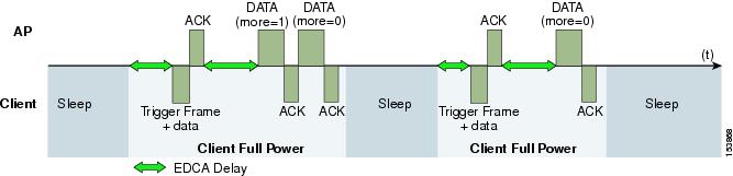
The following figure shows an example of traffic flow with U-APSD.
In this example, the trigger for retrieving traffic is the client sending traffic to the AP. When the AP acknowledges the frame, it indicates the client that data is in queue and must wait. The AP then sends data to the client typically as a transmit opportunity (TXOP) burst where only the first frame has the EDCF access delay. All subsequent frames are then sent directly after the acknowledgment frame. In a Real-Time Traffic over WLAN implementation, only one frame is queued at the AP, and the real-time-capable WLAN client becomes idle after receiving that frame from the AP.
The U-APSD approach overcomes both the disadvantages of the previous scheme, thus making it efficient. The timing of the polling is controlled through the client traffic, which in the case of voice and video is symmetric. If the client is sending a frame every 20 ms, it waits to receive a frame at each 20 ms time interval. This introduces a maximum jitter of 20 ms, rather than n * 100 ms jitter.
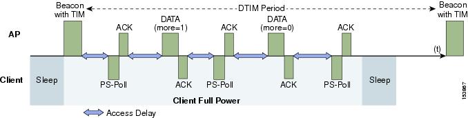
The following figure shows an example frame exchange for the standard 802.11 power-save delivery process.
The client in power-save mode first detects that there is data waiting for it at the AP from the traffic indicator map (TIM) in the AP beacon. The client must power-save poll (PS-Poll) the AP to retrieve that data. If the data that is sent to the client requires more than one frame to be sent, the AP indicates this in the sent data frame. This process requires the client to continue sending power-save polls to the AP until all the buffered data is retrieved by the client.
The standard client power-save has two disadvantages.
- It is inefficient for the PS polls and the normal data exchange to go through the standard access delays associated with distributed coordination function (DCF).
- Retrieving the buffered data is dependent on the DTIM, which is an integer multiple of the beacon interval. Standard beacon intervals are 100 ms. This introduces a level of jitter that is unacceptable for voice and video calls, and voice and video capable wireless endpoints handsets switch from power-save mode to full transmit and receive operation when a call is in progress. This standard client power-save mode gives acceptable voice and video quality but reduces battery life. The Cisco Unified Wireless IP Phones address this issue by providing a PS-Poll feature that allows the phone to generate PS-Poll requests without waiting for a beacon TIM. This allows the device to poll for frames when it has sent a frame, and then go back to power-save mode. This feature does not provide the same efficiency as U-APSD, but improves battery life for Cisco Unified Wireless IP Phones on WLANs without U-APSD.
Traffic Specification Admission Control
Traffic Specification (TSPEC) allows an 802.11e client to signal its traffic requirements to the AP. In the 802.11e media access control (MAC) definition, the following two mechanisms provide prioritized access, both provided by the transmit opportunity (TXOP):With the TSPEC features, a client can specify its traffic characteristics, which automatically results in the use of controlled access mechanism. The controlled access mechanism enables the client to grant a specific TXOP to match the TSPEC request. However, the reverse mechanism is also possible; that is, a TSPEC request can be used to control the use of various ACs in EDCF. In a TSPEC mechanism, a client must send the TSPEC request before it sends any priority-type traffic.
For example, a WLAN client device that requires to use the voice AC must first make a request for use of that AC. You can configure the use of voice and video ACs by TSPEC requests but the use of best effort and background ACs can happen without TSPEC requests.
The use of EDCF ACs, rather than the 802.11e hybrid coordinated channel access (HCCA), to meet TSPEC requests is possible because the traffic parameters are simple to allow them to be met by allocating capacity, rather than creating a specific TXOP to meet the application requirements.
Add traffic stream
The Add traffic stream (ADDTS) function is how a WLAN client performs an admission request to an AP. Signaling its TSPEC request to the AP, the admission request can be in two forms:
- ADDTS action frame: Used when a voice or video call is originated or terminated by a client associated to the AP. The ADDTS contains TSPEC and might contain a traffic stream rate set (TSRS) information element (IE) (Cisco Compatible Extensions Version 4 clients).
- Re-association message: Uses the re-association message when the re-association message contains one or more TSPEC and one TSRS IE if an STA roams to another AP.
The TSPEC element in ADDTS describes the traffic request. Apart from data rates and frame sizes, the TSPEC element also tells the AP the minimum physical rate that the client device will use. This helps to determine the time that the station consumes to send and receive in this TSPEC, therefore allowing the AP to calculate whether it has the resources to meet the TSPEC. The WLAN client (VoIP handsets) uses TSPEC admission control during a call initiation and roaming request. While the WLAN client is roaming, the TSPEC request is appended to the reassociation request.
Related Information
Client connection types
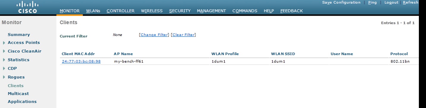
The following figure shows Monitor > Clients page of the Cisco WLAN Controller (WLC) which indicates what Wi-Fi protocol the client used to associate to the WLAN. In the figure below, the client is connected to the 2.4 GHz channel because the protocol is 802.11bn. The client can also be 802.11b, 802.11g or 802.11n. The client is connected to the 5 GHz channel if the protocol is 802.11an. Clicking on the MAC Address link shows the characteristics of the selected client.
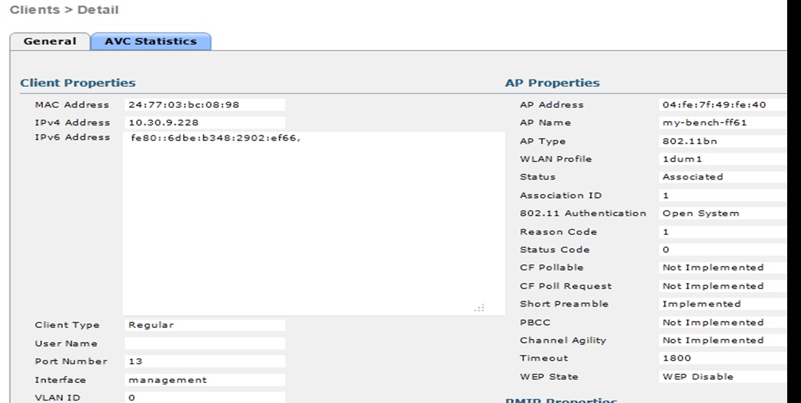
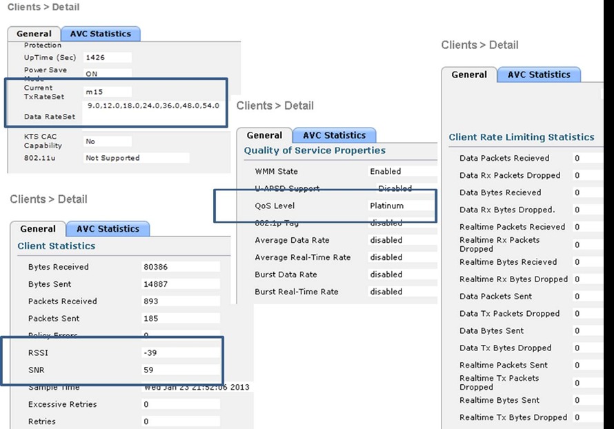
The following figure shows Clients > Detail page, which displays detailed client information available on the WLC. This page displays three important fields and the values about the client connection status:
- Current Tx-Rate-Set: Indicates the data rate, here m15.
- RSSI: A value of -39 dBm indicates a strong signal. For real-time tra applications, the desired receive signal strength indicator (RSSI) is a strength of -67 dBm at the cell edge.
- QoS Level: Set to Platinum, indicates the client can send and receive at the highest WMM priority.
The values in the rate limiting column indicate this client is not part of a rate limiting profile.
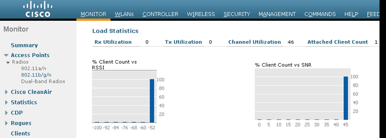
The following figure shows the load statistics of the AP that is associated to the client.
The AP radio is 802.11b/g/n and the channel utilization for the client and the AP is 46 percent. The client and the AP utilization are both 0 percent because they are not sending a significant number of packets to each other. However, the channel that the client and AP are using is very busy with traffic from other APs, other clients, and interference.
The 46 percent channel utilization is above the channel utilization wireless packetized ALOHA standard. The ALOHA protocol defines a radio channel as full when channel utilization reaches 33 percent. This means that the channel is busy, so the packets must wait for an open time slot before they are transmitted. This level of channel utilization is not uncommon with Wi-Fi 2.4 GHz channels. In this scenario, QoS helps to manage channel bandwidth. This is also the reason for Wi-Fi call admission control (CAC). CAC is a part of the 802.11e specification.
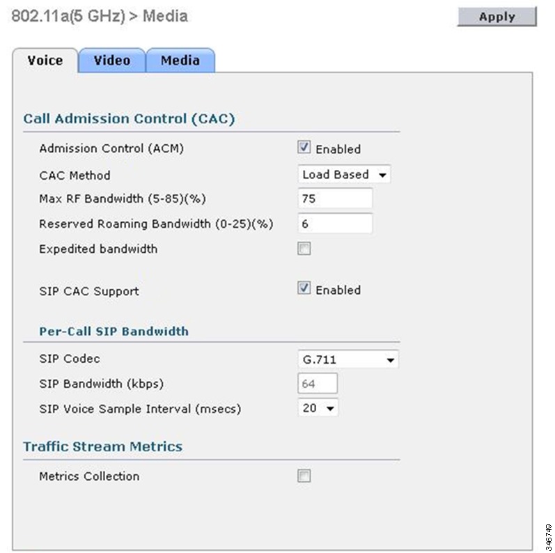
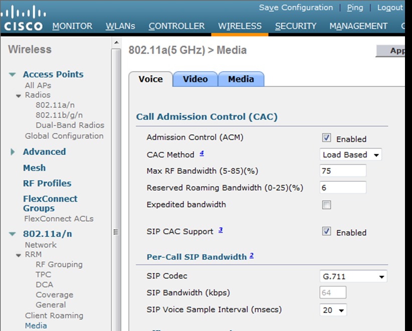
The following figure shows WLC CAC configuration page.
Admission control mandatory (ACM) Load Based CAC for wireless phones and other devices is effective to maintain good quality calls and preserve bandwidth. Load-based CAC measures the load of the Wi-Fi which is best in high density deployments where there is a high level of channel reuse across several APs. Cisco also supports SIP CAC. For SIP CAC, the WLAN must have media session snooping enabled. If the CAC method is load-based, then SIP CAC also uses channel load. Most softphones and smartphones use SIP as the call connection protocol, so SIP CAC is important. When you enable SIP CAC and deploy TCP-based SIP clients, in scenarios where there is not enough bandwidth for a new voice or video call to go through, the WLAN network stops forwarding SIP frames upstream and downstream. Based on client code behavior, this may cause loss of call control registration. In the case of SIP CAC with UDP-based SIP clients, the WLAN network will send a 486 Network Busy message. Based on the client code behavior, client may roam to another AP or terminate call setup. In addition to CAC configuration for voice traffic, there are tabs for video and media traffic. These provide configuration options to extend CAC to video and media. With the help of these tabs, you can configure how the bandwidth of a Wi-Fi channel is divided between real-time voice and video applications and media applications, which in turn determines how much bandwidth remains for data applications.
For SIP-based Cisco WLAN endpoint and mobile client deployments, Cisco recommends not to enable SIP CAC support because they utilize TCP-based SIP versus UDP-based SIP.
QoS advanced features for WLAN infrastructure
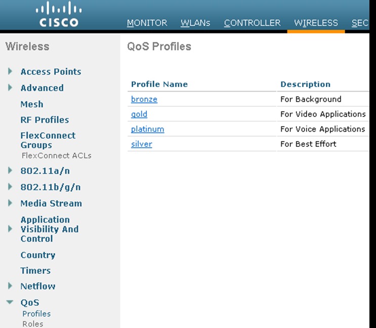
The Cisco Centralized WLAN architecture has multiple QoS features, in addition to WMM support. Cisco WLAN Controller QoS profiles are the primary mechanism for implementing advanced QoS feature. The following four QoS profiles and corresponding traffic types are supported:The following figure shows the four available QoS profiles on the Cisco WLAN Controller.
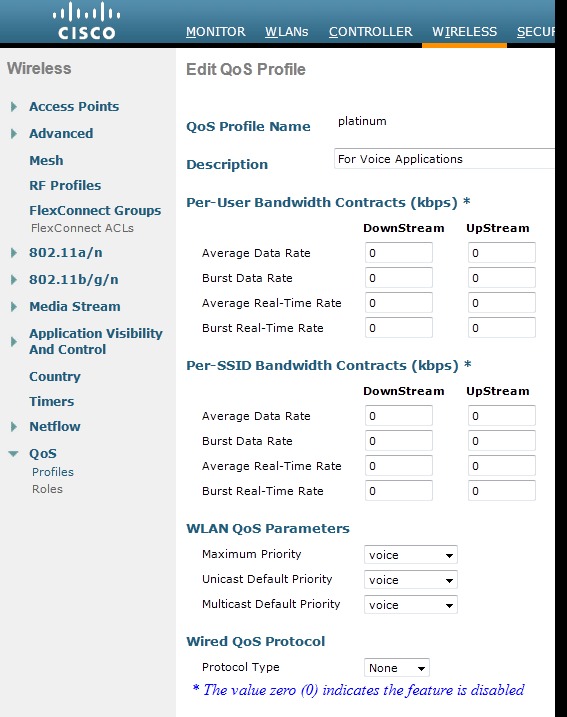
For each profile, you can configure the bandwidth contracts, RF usage control, and the maximum IEEE 802.1P classification that is allowed.
Cisco recommends that you use the default values for Per-User Bandwidth Contracts settings and use IEEE 802.11 WMM features to provide differentiated services.
For WLANs that use a given profile, the IEEE 802.1P classification in that profile controls two important behaviors:
- Determines what class of service (CoS) value is used for packets that are initiated from the WLC. The CoS value that is set in the profile is used to mark the CoS of all CAPWAP packets for WLAN using that profile. So, for a WLAN with platinum QoS profile, and the IEEE 802.1P mark of 6, will have its CAPWAP packets from the AP Manager interface of the controller marked with CoS of 5. The controller adjusts the CoS to be compliant with Cisco QoS baseline recommendations. If the network is set to trust CoS rather than a DSCP at the network connection to the WLC, the CoS value determines the DSCP of the CAPWAP packets that are received by the AP, and eventually the WMM classification and queuing for WLAN traffic, because the WLAN WMM classification of a frame is derived from the DSCP value of the CAPWAP packet carrying that frame.
- Determines the maximum CoS value that can be used by clients that are connected to that WLAN. The IEEE 802.1P classification sets the maximum CoS value that is admitted on a WLAN with that profile.
WMM voice traffic arrives with a CoS of 6 at the AP, and the AP automatically performs a CoS-to-DSCP mapping for this traffic based on a CoS of 6. If the CoS value in the WLC configuration is set to a value less than 6, the WLAN QoS profile at the AP uses this changed value to set the maximum CoS marking used and which WMM AC to use.
The key point in Unified Wireless Network is that you must always consider IEEE 802.11e classifications, and allow the Unified Wireless Network Solution to take responsibility to convert between IEEE classification and the Cisco QoS baseline.
For more information about Per-User Bandwidth Contracts, Per-SSID Bandwidth Contracts, and WLAN QoS Parameters, see the WLC configuration guides that match the WLC code release and model.
You can configure WLAN with various default QoS profiles as shown in the following figure.
Each of the profiles (platinum, gold, silver, or bronze) is annotated with its typical use. In addition, a client can be assigned a QoS profile based on its identity, through authentication, authorization, and accounting (AAA). For a typical enterprise, the WLAN deployment parameters, such as per-user bandwidth contracts and over-the-air QoS, should use the default values, and standard QoS tools, such as WMM and wired QoS, must be used to provide optimum QoS to clients.
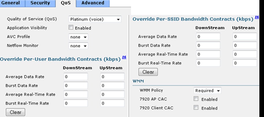
In addition to the QoS profiles, you can also control the WMM policy per WLAN as shown in the preceding figure with the following options:QoS basic service set
The following figure shows the QoS basic service set (QBSS) information element (IE) that a Cisco AP recommends. The Load field indicates the portion of available bandwidth that is currently used to transport data on that AP.
The QBSS in use depends on the WMM and clients settings on the WLAN. Based on the requirements, the following three types of QBSS IEs must be support:Figure 3 shows 7920 AP and Client CAC, components of WLAN Controller (WLC) WLAN configuration that enables the AP to include appropriate QBSS elements in its beacons. WLAN clients with QoS requirements, such as the Cisco Unified Wireless IP Phones, use these recommended QoS parameters to determine the best AP with which to associate.
The WLC provides 7920 CAC support through the client call admission control (CAC) limit, or AP CAC limit. These features are listed below:
- Client CAC limit: The 7920 Client CAC maps to the old QBSS method, which is not clear channel assessment (CCA) based, but only accounts for 802.11 traffic on that specific AP. The client can set a fixed CAC limit, to prevent outbound calls when that limit is reached.
- AP CAC limit: The 7920 AP CAC maps to the new QBSS method, which is CCA-based, and accounts for all energy on the RF channel including 802.11 traffic for the local AP as well as for other APs, and also energy from non-802.11 devices (for example, microwaves and Bluetooth). The client can set a fixed CAC limit, to prevent outbound calls when that limit is reached.
The various combinations of WMM, client CAC limit, and AP CAC limit result in different QBSS IEs being sent:
- If only WMM is enabled, IE number 2 (IEEE 802.11e standard) QBSS Load IE is sent out in the beacons and probe responses.
- If 7920 Client CAC limit must be supported, IE number 1 (the pre-standard QBSS IE) is sent out in the beacons and probe responses on the bg radios.
- If 7920 AP CAC limit must be supported, the number 3 QBSS IE is sent in the beacons and probe responses for bg radios.
Note
The various QBSS IEs use the same ID, and therefore the three QBSSs are mutually exclusive. For example, the beacons and probe responses can contain only one QBSS IE.
Setting the admission control parameters
The following figure shows a sample configuration screen for setting the voice parameters on the controller.
For SIP-based Cisco WLAN endpoint and mobile client deployments, Cisco recommends not to enable SIP CAC support because they utilize TCP-based SIP versus UDP-based SIP.
The admission control parameters consist of the maximum RF Bandwidth that a radio can use and still accept the initiation of a voice or video over WLAN call through a normal ADDTS request. The reserved roaming bandwidth is the capacity set aside to respond to the ADDTS requests during association or re-association, which are RToWLAN clients with calls in progress trying to roam to that AP.
Check the Admission Control (ACM) check box to enable admission control based on these parameters. This enables admission control based upon the AP capacity, but does not consider the possible channel loading impact of other APs in the area. To include this channel load in capacity calculations, select Load Based from the CAC Method drop down and check the Admission Control (ACM) check box.
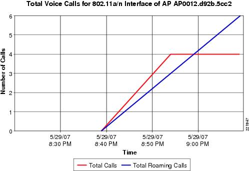
The following figure shows an example of voice statistics reports that are available on the WCS, which displays the calls that are established on the radio of one AP, and the number of calls that roamed to that AP. This report and other voice statistics can be scheduled or ad hoc, and either graphically displayed or posted as a data file.
Note
Call admission control is performed only for voice and video QoS profiles.
Impact of TSPEC admission control
The purpose of TSPEC admission control is to protect the high-priority resources. Therefore, a client that has not used TSPEC admission control does not have its traffic blocked but its traffic is reclassified if it tries to send, which it must not do if the client is transmitting WMM-compliant traffic in a protected AC.
The following tables describe the impact on classification if admission control is enabled, depending on whether a traffic stream has been established.
Table 3 Upstream Traffic Traffic Stream Established
No Traffic Stream
No admission control
No change in behavior; the packets go into the network. UP is limited to max=WLAN QoS setting.
No change in behavior; the packets go into the network. UP is limited to max=WLAN QoS setting.
Admission control
No change in behavior; the packets go into the network. UP is limited to max=WLAN QoS setting.
Packets are re-marked to BE (both CoS and DSCP) before they enter the network for WMM clients. For non-WMM clients, packets are sent with WLAN QoS.
IEEE 802.11e, IEEE 802.1P, and DSCP mapping
In a Unified Wireless network, WLAN data is tunneled through CAPWAP (IP UDP packets). To maintain QoS classification applied to WLAN frames, a process of mapping classifications to and from DSCP to CoS is required.
For example, when a WLAN client sends WMM classified traffic, it has an IEEE 802.1P classification in its frame. The AP must translate this classification into a DSCP value for the CAPWAP packet carrying the frame, to ensure the packet is treated with the appropriate priority as it reaches WLC. A similar process must occur on the WLAN Controller (WLC) for CAPWAP packets going to the AP.
A mechanism to classify traffic from non-WMM clients is also required, to ensure the AP and WLC give an appropriate DSCP classification to the CAPWAP packets for non-WMM clients.
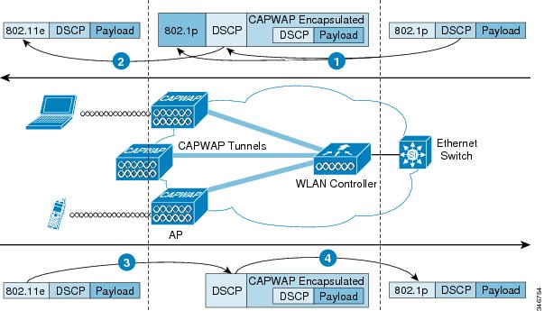
The following figure shows a numbered example of the traffic classification flow for a WMM client, an AP, and a WLC.
The traffic classification flow is described as follows:
- A frame with an 802.1P marking and a packet with an IP DSCP marking arrive at the WLC wired interface. The IP DSCP of the packet determines the DSCP of the CAPWAP packet leaving the WLC.
- The IP DSCP of the CAPWAP packet reaching the AP translates to an 802.11e CoS marking.
- The 802.11e CoS marking of a frame arriving at the AP translates to an CAPWAP DSCP value, capped at the maximum value for that QoS profile.
- CAPWAP control frames require prioritization, and CAPWAP control frames are marked with a DSCP classification of CS6.
- WMM-enabled clients have the classification of their frames mapped to a corresponding DSCP classification for CAPWAP packets to the WLC. This mapping follows the standard IEEE CoS-to-DSCP mapping, with the exception of the changes that are necessary for QoS baseline compliance. This DSCP value is translated at the WLC to a CoS value on IEEE 802.1Q frames leaving the WLC interfaces.
- Non-WMM clients have the DSCP of their CAPWAP tunnel set to match the default QoS profile for that WLAN. For example, the QoS profile for a WLAN supporting wireless IP phones would be set to Platinum, resulting in a DSCP classification of EF for data frames packets from that AP WLAN.
- CAPWAP data packets from the WLC have a DSCP classification that is determined by the DSCP of the wired data packets that are sent to the WLC. The AP table converting DSCP to WMM classification determines the IEEE 80211.e classification used when sending frames from the AP to a WMM client.
Note
The WMM classification that is used for traffic from the AP to the WLAN client is based on the DSCP value of the CAPWAP packet, and not the DSCP value of the contained IP packet. Therefore, it is critical that you have an end-to-end QoS system in place.
QoS baseline priority mapping
The CAPWAP AP and WLC perform QoS baseline conversion to ensure that WMM values are mapped to the appropriate QoS baseline DSCP values, rather than the IEEE values.
Table 5 Access Point QoS Translation Values Traffic Type
IP DSCP
QoS Profile
802.1p
IEEE 802.11e UP
Inter-network control (CAPWAP control, 802.11 management)
48 (CS6)
Platinum
6
7
Voice
46 (EF)
Platinum
5
6
Interactive video
34 (AF41)
Gold
4
5
Mission critical
26 (AF31)
Gold
3
4
Call signaling
24 (CS3)
Gold
3
4
Transactional
18 (AF21)
Silver
2
3
Bulk data
10 (AF11)
Bronze
1
2
Best effort
0 (BE)
Silver
0
0
Scavenger
2
Bronze
0
1
The following table shows the translations values if AP is translating CoS values, for example, autonomous APs.
Table 6 WMM Packet Re-marking for APs with Priority Type Configured Downstream L2 Packet Re-marking
1Upstream L2 Packet Re-marking
Typical Application
CoS
WMM UP
802.1d Designation
WMM UP
CoS
Best Effort Data
0
0
BE
0
0
Medium Priority Data
1
2
BK
1
1
High Priority Data
2
3
-
2
1
Call Signaling
3
4
EE
3
2
Video Conferencing
4
5
CL
4
3
Voice Bearer
5
6
VI
5
4
Reserved
6
7
VO
6
5
Reserved
7
7
NC
27
7
1In the downstream direction, the AP takes CoS markings on the wired interface and maps them to the UPs shown. In the upstream direction, the AP takes UPs that are received on the dot11 interface and maps them to CoS on the wired interface. Using this remapping results in the best match of WMM AC to CoS.
2The only network control traffic that must get mapped to CoS=7 is spanning-tree traffic that is used when work group bridges are deployed or when outdoor bridges are deployed, connecting the LANs between two or more buildings. Even though 802.11 MAC management traffic is carried on UP=7 in autonomous APs, is it not bridged onto the wired port of the AP.
Deploying QoS features on CAPWAP-based APs
Consider the following when you deploy QoS on wireless APs:
- The wired CAPWAP AP interface reads or writes Layer 2 CoS (IEEE 802.1P) information. The WLC and APs depend on Layer 3 classification (DSCP) information to communicate WLAN client traffic classification. The intermediate routers can modify this DSCP value and therefore the Layer 2 classification that is received by the destination does not reflect the Layer 2 classification that is marked by the source of the CAPWAP traffic.
- The APs no longer use NULL VLAN ID. As a result, L2 CAPWAP does not effectively support QoS because the AP does not send the IEEE 802.1P/Q tags, and in L2 CAPWAP there is no outer DSCP on which to fall back.
- APs do not reclassify frames; they prioritize based on CoS value or WLAN profile.
- APs use EDCF-like queuing on the radio egress port only.
- APs use first-in first-out (FIFO) queuing only on the Ethernet egress port.
WAN QoS and FlexConnect
For WLANs that have data traffic forwarded to the WLC, the behavior is same as non-FlexConnect APs (formerly hybrid remote edge access point or H-REAP) APs. For locally switched WLANs with WMM traffic, the AP marks the 802.1P value in the 802.1Q VLAN tag for upstream traffic. This occurs only on tagged VLANs; that is, not native VLANs.
For downstream traffic, FlexConnect uses the incoming 802.1Q tag from the Ethernet side and uses this to queue and mark the WMM values on the radio of the locally switched VLAN.
The WLAN QoS profile is applied both for upstream and downstream packets. For downstream, if you receive an IEEE 802.1P value that is higher than the default WLAN value, the default WLAN value is used. For upstream, if the client sends a WMM value that is higher than the default WLAN value, the default WLAN value is used. For non-WMM traffic, there is no CoS marking on the client frames from the AP.
Wireless QoS deployment guidelines
The guidelines that you consider when you deploy QoS in a wired network apply when you deploy QoS in a wireless network. QoS does not create additional bandwidth; it prioritizes and optimizes the bandwidth that is allocated to different applications.
Successful wireless QoS requires awareness of the types of traffic and protocols traversing the network, and understanding of the specific delay sensitivity and bandwidth requirements of applications to properly design and configure WLAN QoS.
Throughput
It is important to consider and understand the offered traffic when you deploy IEEE 802.11 QoS. You must consider both bit rate and frame size, because IEEE 802.11 throughput is sensitive to the frame size of the offered traffic.
The following table shows how frame size affects throughput; a decrease in the packet size decreases the throughput.For example, if an application that offers traffic at a rate of 3 Mbps is deployed on an 11 Mbps IEEE 802.11b network, but uses an average frame size of 300 bytes, no QoS setting on the AP allows the application to achieve its throughput requirements. This is because IEEE 802.11b cannot support the required throughput for that throughput and frame size combination. The same amount of offered traffic, having a frame size of 1500 bytes, provides better throughput.
AP wired switch attachment
The QoS configuration of the AP switch is relatively trivial because the switch must trust the DSCP of the CAPWAP packets that are passed to it from the AP. There is no class of service (CoS) marking on the CAPWAP frames that come from the AP.
The use of IOS command mls qos trust dscp at the access switch enables trust of DSCP markings of the AP as set by the WLC policy. The maximum DSCP value that is assigned to client traffic is based on the QoS policy that is applied to the WLANs on that AP.
The above configuration command addresses only packet classification. Depending on local QoS policy, you can add queuing commands and other QoS-related configuration.
WLC wired switch attachment
The QoS classification on a WLC-connected switch is more complex than on the AP-connected switch because you must decide to trust either the DSCP or the CoS of traffic coming from the WLC. The following factors help to decide on the QoS switch configuration:
- Traffic leaving the WLC can either be upstream (to the WLC or network) or downstream (to the AP and WLAN clients). The downstream traffic is CAPWAP encapsulated, and the upstream traffic from AP and WLAN clients is either CAPWAP encapsulated or decapsulated WLAN client traffic, leaving the WLC.
- QoS policies on the WLC control the DSCP values of CAPWAP packets. The WLAN client does not alter the DSCP values that are set on the WLAN client traffic encapsulated by the CAPWAP tunnel header.
- The WLC QoS policies set the CoS values of frames leaving the WLC, regardless of whether they are upstream, downstream, encapsulated, or decapsulated.
The use of the mls qos trust cos IOS command enables the trust of the CoS settings of the WLC. This allows a central location for the management of WLAN QoS, rather than managing the WLC configuration and an additional policy at the WLC switch connection. Customers who want a more precise degree of control can implement QoS classification policies on the WLAN-client VLANs.
Application visibility and control (AVC) for wireless
Cisco wireless AVC benefits include:
- Improved quality of experience for all wireless users through application-level optimization and control.
- Proactive monitoring and end-to-end application visibility to accelerate troubleshooting and minimize network downtime.
- Network capacity management and planning through greater visibility of application usage and performance.
- Prioritization of business-critical applications and subflows like Cisco Jabber voice or IM sessions.
AVC functionality
AVC on the Wireless LAN Controller has the functionality and features that are comparable to AVC found on other Cisco products. AVC application recognition is configurable down to the WLAN/SSID. Each WLAN can optionally enable various AVC parameters making any WLAN unique. WLANs define the name of the SSID with which the clients authenticate and associate. The same WLAN configuration also defines the highest level of Wi-Fi QoS for packet transmission over the Wi-Fi channel. A packet remarked by an AVC profile will not have a QoS priority that is above the QoS priority that is defined by the WLAN setting. For example, if WLAN is created for guest users with the QoS priority level of best-effort. Voice and video packets are transmitted at a best-effort priority, even if the AVC policy recognizes the packet as an audio packet. The guest SSID can be configured to limit "FaceTime" calls to the best-effort priority. Also, the same guest SSID can be configured to use an AVC profile that blocks "You Tube" thus providing more bandwidth on other SSIDs that share the same Wi-Fi channel.
For Wi-Fi clients that are associated to a WLAN, AVC on the Wireless LAN Controller uses application recognition through deep packet inspection to determine how packets of a particular application should be handled per the Wireless LAN Controller AVC configurations. The Wireless LAN Controller is the control point for blocking packets and changing the QoS marking of packets. You can block the FaceTime application from connecting to the servers that establishes a FaceTime call. The blocking occurs at the Wireless LAN Controller. When the AVC profile blocks an application, the client device remains associated to the WLAN. If AVC profile is created to remark the FaceTime application packet, the remarking occurs at the Wireless LAN Controller. The remarking is done in the upstream and downstream direction. In the case of upstream traffic (from Wi-Fi endpoint to Wireless LAN Controller through the AP), the packet remarking is from the Wireless LAN Controller to the packets that are being forwarded to the destination endpoint. AVC cannot control the QoS packet markings at the source client or the markings of those packets because they are forwarded from the AP to the Wireless LAN Controller. In the case of downstream traffic (endpoint packets being forwarded by the Wireless LAN Controller through the AP to the Wi-Fi endpoint), the packet remarking occurs at the Wireless LAN Controller. The AP forwards the FaceTime traffic to the WLAN with 802.11e/WMM QoS priorities that is representative of the DSCP values assigned in the AVC FaceTime profile.
CAPWAP is the protocol that connects the APs and the Wireless LAN Controllers. CAPWAP packets encapsulate IP application packets. CAPWAP QoS packet markings upstream are based on 802.11e/WMM QoS values of the Wi-Fi header of the endpoint application packet. CAPWAP QoS packet markings downstream are based on the WLAN configurations. In the FaceTime example, the DSCP values on the header of the CAPWAP packets are assigned at the Wireless LAN Controller by the DSCP values that are configured in the AVC profile for FaceTime. You can configure AVC profiles for each Wireless Lan Controller and assign to the WLANs.
Note
AVC configuration options for Wireless LAN Controller Version 7.4 and higher are provided in the Wireless LAN Controller configuration guides by Wireless LAN Controller release code version numbers. You can download the Wireless LAN Controller release configuration guides from Cisco.com. A separate WLC/AVC configuration guide is available by Wireless LAN Controller hardware type on the same Cisco product page as the Wireless LAN Controller software page.
AVC versions
The Wireless LAN Controller version of AVC runs as part of Wireless LAN Controller and does not require a separate license. AVC on the Wireless LAN Controller became available with Cisco Wireless LAN Controller Release 7.4.
Supported by the Wireless LAN Controller AVC are FTP/TFTP loads of Network Based Application Recognition (NBAR) protocol packs that are release matched to the NBAR engine version incorporated in the Wireless LAN Controller release. For example, the Wireless LAN Controller Release 7.5 uses NBAR engine version 13. Hence, protocol packs that are released for Release 7.5 will have a numbering that is similar to pp-AIR-7.5-13-4.1.1.pack.
You can determine the version of the protocol pack and AVC engine by executing the following Wireless LAN Controller CLI commands:You can download the AVC NBAR2 Protocol Packs by the Wireless LAN Controller type from the same download page location as the software release versions for the Wireless LAN Controller posted on Cisco.com.
Traffic shaping, over-the-air QoS, and WMM clients
Traffic shaping and over-the-air QoS are useful tools in the absence of WLAN WMM features, but they do not help to prioritize IEEE 802.11 traffic directly. For WLANs that support WMM clients or wireless handsets, you must use the WLAN QoS mechanisms of these clients without using traffic shaping or over-the-air QoS.