Contents
Real-Time Traffic over WLAN Radio Frequency Design
The chapter describes, in general terms, the radio frequency (RF) plan and design considerations for RToWLAN deployment. The other factors that affect the RF plan and design considerations are endpoint capabilities, local conditions, and regulations. This chapter presents typical deployment scenarios to illustrate RF-related processes and considerations.
- High availability
- Capacity planning
- Coverage hole algorithm
- Design considerations
- 802.11n and 802.11ac protocols
High availability
High availability (HA) is an important factor when you consider a system plan that includes RToWLAN. For an RToWLAN deployment, you can apply the same HA strategies that you use in wired networks, to the wired components of the RToWLAN solution. A unique factor to RToWLAN availability that you must consider is the RF coverage HA, that is, providing RF coverage that is not dependent on a single WLAN radio. The primary mechanism to provide RF HA is cell boundary overlap.
An overlap of 20 percent means that 80 percent of a given access point (AP) cell is also covered by other APs at the recommended signal levels, while in the other 20 percent of the cell RToWLAN calls are of degraded quality, but are still available. The Cisco Unified Wireless Network Coverage Hole algorithm amplifies the RF HA coverage, which detects if WLAN clients are experiencing poor signal-to-noise ratio (SNR) values and causes the power of APs to increase as needed to rectify SNR issues.
Note
In deployments planning to rely on the Coverage Hole algorithm, the planning must consider whether an AP is going to increase its power level to adjust for a hole. Therefore, the maximum power of the RToWLAN endpoint, which can be lower than the maximum power of the AP, needs to be considered when configuring the initial AP power level.
Related References
Capacity planning
Capacity planning is another important parameter in an RToWLAN plan. Call capacity is the number of simultaneous RToWLAN calls that an area can support. The number of calls can vary depending on the RF environment, the RToWLAN endpoint features, and the WLAN system features.
Cisco strongly recommends the use of the 5 GHz spectrum channels for RToWLAN design, especially when video is part of the media that is to be transmitted over the WLAN.
The following table provides three examples of the best case scenario approximate maximum capacity per access point or channel for video calling when endpoints use a WLAN that provides optimized WLAN services (such as the Cisco Unified Wireless Network). These examples consider an RToWLAN that uses 5 GHz channel of the 802.11n WLAN standard, with no Bluetooth, and with no channel bonding.
Table 1 Video over WLAN Call Capacity Estimated maximum number of simultaneous bidirectional Video Calls
Resolution/Bitrate
WLAN Standard
Data Rate/MCS Index
7
H.264 720p/2500 Kbps
802.11n
MCS 7 (40 MHz Channels)
4
H.264 720p/2500 Kbps
802.11n
MCS 4 (40 MHz Channels)
1
H.264 720p/2500 Kbps
802.11n
MCS 1 (40 MHz Channels)
16
H.264 360p/400 Kbps
802.11n
MCS 7 (40 MHz Channels)
12
H.264 360p/400 Kbps
802.11n
MCS 4 (40 MHz Channels)
8
H.264 360p/400 Kbps
802.11n
MCS 1 (40 MHz Channels)
Because the 5 GHz spectrum features less noise and interference, there can be greater capacity with the higher carrier frequency implementation. The additional nonoverlapping channels that are available in the 5 GHz spectrum also provide higher call capacity for a given area. In addition, it is recommended to use the 40 MHz channels for video because they provide increased capacity. Consider as well that these maximum approximate numbers vary according to your particular environment noise, coverage, attenuation, Bluetooth utilization, channel utilization, how many spatial streams the endpoint in question supports, and the mix of clients in the cell.
The following table provides two examples of the estimated maximum capacity per access point or channel for voice calling when endpoints use a WLAN that provides optimized WLAN services. These examples consider an RToWLAN that uses a 5 GHz channel of the 802.11a WLAN standard and with no channel bonding.
Table 2 Voice over WLAN Call Capacity Estimated maximum of simultaneous bidirectional Voice Calls
Audio Codec/Bit Rate
WLAN Standard
Data Rate
20
G.711-G.722/64 Kbps
802.11a
12 Mbps
27
G.711-G.722/64 Kbps
802.11a
24 Mbps or higher
Note
The call capacities mentioned above are per nonoverlapping channel because, here, channel capacity becomes the limiting factor and not the number of APs. These maximum call capacity numbers are provided for general planning purposes. You must use the call capacity that is specified by the actual RToWLAN endpoint for deployment, because this is the supported capacity of that endpoint. Additionally, Cisco recommends that you use 40 MHz channel when you utilize the 5 GHz band. For more information to determine accurate values for call capacity planning, see the endpoint documentation.
Coverage hole algorithm
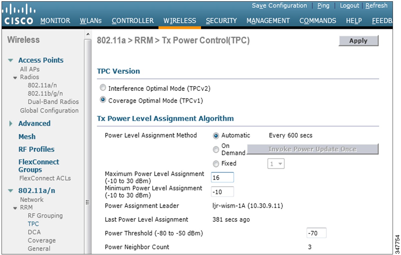
In deployments that plan to rely on coverage hole algorithm, during planning, you must consider whether an AP is going to increase its power level to adjust for a hole. Therefore, the maximum power of the RToWLAN endpoint, which can be lower than the maximum power of the AP, must be considered when you configure the initial AP power level. For example, if the RToWLAN endpoint has a maximum power level of 16 dBm and the initial AP power level is 16 dBm, increasing the AP power to cover an RF hole does not help a RToWLAN client in that hole, because the RToWLAN will not be able to increase its power level any further to compensate for the increased power from the AP. In this example, for the hole coverage to be effective, the initial AP power level should be 13 dBm or less such that both the AP and the RToWLAN have sufficient room to increase power to cover an RF hole.
If you place APs with a design goal to support media-rich and real-time applications, the population of APs relatively changes from dense to highly dense. The remote management module (RMM) power level assignments of levels 3 and 4 are of medium density and the power levels of 5 through 8 are highly dense. If the AP placement is such that the RMM has assigned power levels of 1 or 2, the coverage is not considered dense. At AP power level of 1, the APs surrounding an AP which drops out of the network are not able to increase their power. They will not be able to cover the hole that was created by an AP that is going off line. If the power levels of the surrounding APs was 2, the surrounding APs would increase the power level to 1.
If minimum density is a design goal, then you must do the survey process and initial coverage evaluations with the actual APs and the actual antennas that are to be installed. Then set the maximum transmit power in dBm in RMM to the maximum transmit power of the weakest client. The initial AP placements should be such that their coverage area is no greater than the coverage area of the weakest client. Set the dBm value in RRM to equal the dBM transmit power of the weakest mobile client so that the coverage of the APs match the coverage of the clients.
The following figure shows the transmit power control settings of a Cisco WLAN.
All clients that use 802.11g, 802.11a, 802.11n, or 802.11ac take advantage of client link downstream and maximum ratio combining (MRC) upstream. This is a dynamic Wi-Fi per client quality of signal enhancement and can be effective when there are coverage holes from AP outages.
Design considerations
This section describes important elements that you must consider when you design RF coverage for wireless endpoints using RToWLAN.
General AP guidelines for rich media
The packet loss and jitter requirements of rich media and the increased mobility of RToWLAN endpoint users place demands on connection quality and coverage that are beyond that of a typical WLAN data deployment. Although later generations of WLAN equipment and software can provide further RToWLAN improvements, the foundation of a successful RToWLAN deployment depends on radio frequency planning, designing , and implementing. It is important that you design, plan, implement, operate, and maintain the WLAN RF environment to make the RToWLAN deployment successful. The processes, guides, heuristics, and tools that are used for a WLAN data deployment do not help to deliver a successful RToWLAN deployment.
The general RToWLAN guidelines for an optimal RToWLAN network are as follows:
- Cell overlap of at least 20 percent and overlap of approximately 20-30 percent for critical communications for industries like healthcare, where a WLAN Data design can use an AP cell overlap of 5-10 percent.
- Cell boundary of -67 dBm.
Note
Cisco strongly recommends the use of 5 GHz spectrum channels for RToWLAN design, especially when video is part of the media that is to be transmitted over the WLAN. If possible, use the 40 MHz channels instead of the 20MHz.
- If you use 802.11n AP platforms, use ClientLink/beamforming to optimize the WLAN performance.
- For optimal performance of voice or video deployments, data rates that are below 12 Mbps should be disabled (including MCS 0).
Note
The RF characteristics of RToWLAN endpoints vary, and can affect the WLAN design and capacity greatly. If you are planning a deployment of an RToWLAN endpoint with RF deployment requirements that do not match with those that are presented in this chapter, then you must follow the endpoint guidelines. Although endpoint recommendations vary, the general principles and issues that are discussed in this chapter still apply with changes in cell sizes.
2.4 GHz network design
Cisco recommends that you use the 5 GHz spectrum channels for RToWLAN design.
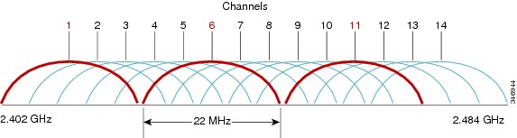
The IEEE 802.11b/g channel set defines a total of 14 channels. Each channel is 22 MHz wide, but the channel separation is only 5 MHz. This leads to channel overlap such that signals from neighboring channels can interfere with each other.
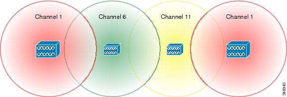
In a 14-channel DS system (11 usable channels in the U.S.), there are only three nonoverlapping (and thus, noninterfering) channels, namely 1, 6, and 11, each with 25 MHz of separation. This channel spacing administers the use and allocation of channels in a multi-AP environment, for example an office or campus. APs are usually deployed in a cellular fashion within an enterprise, where adjacent APs are allocated nonoverlapping channels. See the following figure, which illustrates 2.4 GHz channel allocations.
IEEE 802.11b provides data rates of 1, 2, 5.5, and 11 Mbps. IEEE 802.11g provides data rates of 6, 9, 12, 18, 24, 36, 48, and 54 Mbps in the 2.4 GHz band, in the same spectrum as IEEE 802.11b. IEEE 802.11g is backward-compatible with IEEE 802.11b with a single AP providing WLAN access for both IEEE 802.11b and IEEE 802.11g clients.
Co-channel interference considerations
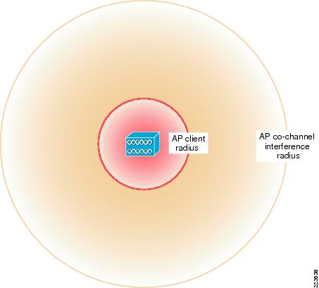
As mentioned in the preceding section, there are only three nonoverlapping channels in U.S. 2.4 GHz spectrum. Therefore, it is difficult when you try to deploy APs and ensure that APs on the same channel do not receive signal from other APs on the same channel. The AP coverage radius changes with the client bit rates that are supported, and the boundary that is created by this radius is considered the AP boundary.
In reality, co-channel interference becomes complicated because the AP influences the WLAN RF environment around it for a much larger distance than just the bit rate boundary. This is because the RF energy from the AP, although too low to be demodulated in to a WLAN frame, is strong enough to cause an IEEE 802.11 radio to defer sending. In addition to the AP influence of the RF environment, the clients that are associated with that AP extend the range of the RF energy that is associated with that APs cell even further.
The IEEE 802.11 MAC is a Carrier Sense Multiple Access-Collision Avoidance (CSMA-CA) algorithm, and the Carrier Sense performs a Clear Channel Assessment (CCA) before it attempts to send an IEEE 802.11 frame. The CCA mechanism is specified for each IEEE 802.11 physical layer; it is triggered either by a simple raw energy level, and Physical Layer Convergence Protocol (PLCP) header power levels, or carrier detection. The CCA of an IEEE 802.11 radio does not vary with the bit rates that are being used and is not, generally, user-configurable.
The impact of CCA deferrals on an AP WLAN from IEEE 802.11 radios that are not part of that AP WLAN is called co-channel interference. As co-channel interference results in delays in sending frames, it causes increased jitter and delay during RToWLAN calls. Although WLAN QoS prioritizes WLAN traffic, this occurs after the CCA and therefore prioritization does not overcome the jitter and delay that are introduced by CCA.
An RToWLAN endpoint must have a power level boundary of -67 dBm and a separation between adjacent AP channels of -86 dBm. The -67 dBm requirement is to minimize packet loss, and the -86 dBm requirement provides separation between adjacent channel cells to minimize co-channel interference from other AP cells on the same channel.
The following figure shows an example of the two boundaries that are created by the -67 dBm and -86 dBm requirements, based on standard RF loss formulas for an open office environment.
This RF environment, which would give an AP a client radius of 43 feet, which gives an AP co-channel interference radius of 150 feet using standard antenna gain (2 dB), and an AP output power of 16 dBm (40 mW). Different RF environments, AP powers, and antennas provide different client and co-channel interference radii, but the principles that are discussed in this chapter still apply.
Note
The output power that you choose for the AP must align with the RToWLAN endpoint capabilities and deployment requirements. For example, the 9971 collaboration endpoint has a maximum output power of 40 mW (16 dBm) when using 802.11a. An AP power greater than 40 mW must not be used for a 9971 collaboration endpoint deployment if 802.11a is used. In circumstances where the Cisco Unified Wireless Network Hole Coverage mechanism that is expected to provide RToWLAN coverage in the event of an AP outage, an AP power of less than 40 mW (using the 9971 collaboration endpoint as an example) must be used for AP planning to allow the APs covering an RF hole to operate in a range that is suitable for the RToWLAN endpoint.
One additional advantage of using a lower AP transmit power is a proportional decrease in the co-channel interference radii. In the preceding example, a 40 mW (16 dBm) transmit power gives a co-channel radius of the 150 feet and a client radius of 43 feet. A decrease in the power to 20 mW (13 dBm) reduces the co-channel radius to 130 feet and the client radius to 38 feet, and also reduces the co-channel interference proportional to the co-channel interference that is generated by an AP.
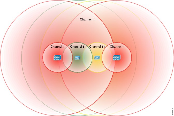
The RF co-channel interference radius of an AP as well as a WLAN client contribute to the co-channel interference. See the following figure.
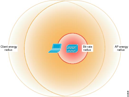
The client co-channel interference is better illustrated in the following figure provided a client or clients can be located anywhere on the bit rate radius perimeter. With the 43 foot bit rate radius and 150 feet AP co-channel interference radius of the previous calculations, 193 foot is the new client co-channel interference radius.
Note
The 193-foot radius represents close to a worst case because the WLAN client is not normally in an equivalent location to an AP and will likely suffer greater signal attenuation due to obstacles.
Bit rate impact on co-channel interference
The AP client radius in the example results in a nominal bit rate for the RToWLAN endpoints of approximately 24 Mbps or greater, depending on noise. You can extend the AP client radius further by lowering the bit rates. But, this is not recommended for the following reasons:
- Lowering the bit rate extends the AP client radius, but also increases the client co-channel interference radius, increasing the area that has the RToWLAN call capacity of only a single AP. Furthermore, lower bit rate reduces video call quality.
- Lowering the bit rate reduces the overall call cell capacity, because lower bit rate packets consume more time, and transmit fewer packets.
RToWLAN call quality is sensitive to data rate shifting. The decision to make a data rate shift is normally the result of being unable to send frames at the data rate that was previously used, which is determined by sending a frame multiple times without receiving an acknowledgment for that frame. This increases the delay and jitter during an RToWLAN call.
Some clients can utilize the traffic stream rate set (TSRS) IE to use a subset of enabled data rates (for example, 12-24) to help first transmission success.
20 percent cell overlap
It is recommended that you use an AP cell overlap of at least 20 percent for RToWLAN deployments. This ensures RToWLAN endpoint can detect and connect to alternative APs, when it is close to the cell boundary. It also allows an RToWLAN client to change AP associations with a minimum interruption to a call, by minimizing the amount of data rate shifting and retransmission at a cell boundary for a given RToWLAN client.
The 20 percent overlap requirement means that APs are spaced closer together than the two-times-70 feet distance suggested by the cell boundary. The area of overlap between two circles of radius is equal to 1. d is the distance between the centers of each circle. For an area of 20 percent, the value of d is 1.374 for a standard radius of 1, or 59 feet between APs for our 67 dBm boundary.
Note
The other common distance values that are used are 10 percent (1.611), 15 percent (1.486), 25 percent (1.269), and 30 percent (1.198).
The following figure illustrates 20 percent AP overlap.
Co-channel interference and 20 percent AP cell overlap
The following figure shows an APs with 20 percent overlap and their co-channel interference boundaries.
The co-channel interference boundary for one of the APs using channel 1 overlaps with an AP using the same channel. In this case, co-channel interference occurs in an RToWLAN deployment. You must also note that the combined effect of the 20 percent overlap requirement for reliable roaming between AP cells and the impact of co-channel interference is a reduced per RToWLAN channel cell call capacity over a given area.
Note
It is not effective to reduce overlap in order to reduce co-channel interference. This results in poor roaming performance and reduces user satisfaction. In contrast, you can address call capacity while you plan and design.
Existing WLAN data deployments (that initially used lower-power cell-boundaries and less overlap) that are changed to match recommended power boundaries and overlap for RToWLAN can experience application issues for time-sensitive applications. It is difficult to predict which applications can be affected by the WLAN changes, because the actual effect depends on the application implementation. In general, custom applications that require keepalive timeouts are most likely to be affected, and must be validated in the new environment to ensure that their timers require no adjustment.
Deployment examples
The AP layout within a building depends on the building construction and shape, and the WLAN coverage requirements in that building. Due to different effects of implementation-specific variables, there is not a single recommended deployment for the number of APs that you must deploy nor a single solution to determine the effect of co-channel interference. The following sections describe the design process with examples that illustrate deployment types:Single-floor building deployment example
The illustrations for the single-floor deployment with 20 APs and 15 APs do not show the location of building exits. It is critical that there is coverage around the building exits if not between the buildings.
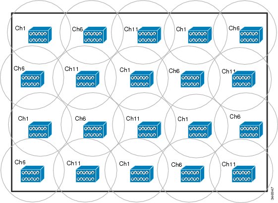
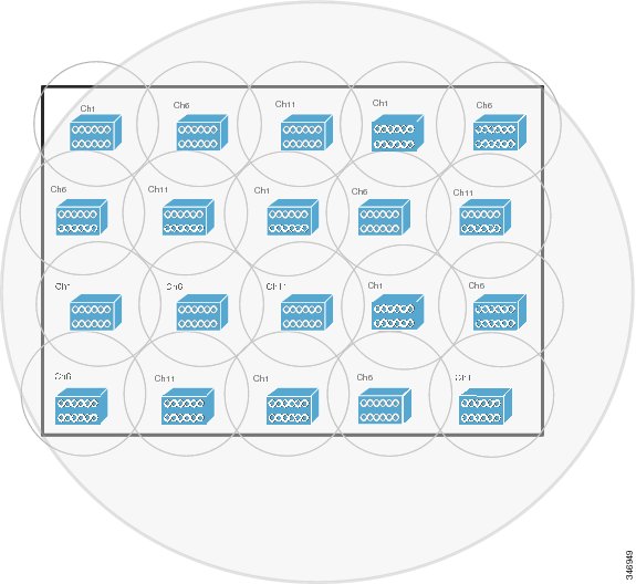
The following figure shows a rectangular building with a dimension of 285 feet x 185 feet that will require 20 APs to give complete coverage.
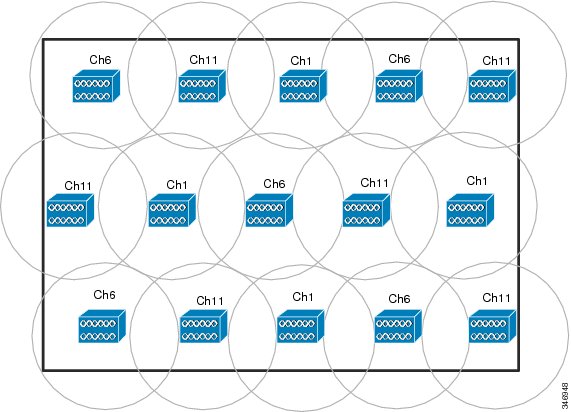
A WLAN data deployment with the same AP boundary and plan will be able to use only 15 APs, but this gives small coverage gaps and less overlap, as shown in the following figure. One of the characteristics of RToWLAN deployments is that users are more mobile and find coverage gaps that WLAN data clients cannot find. Therefore, it is preferred that you use a 20 AP deployment.
The following figure shows the co-channel interference radius of an example AP where the co-channel interference radius extends for the entire building. This means the APs that are using channel 1 are effectively sharing channel capacity. The six channel 1 APs have increased the coverage over single AP by six times, but not increased the capacity by the same ratio, and might not increase the capacity significantly in comparison with single AP. This is applicable for the APs on other channels. Because of co-channel interference, the call capacity of the floor is equivalent to something above the capacity of three independent APs, but not approaching the capacity of 20 APs. This is the primary reason to address RToWLAN call capacity in terms of the number of calls per channel, and not the number of calls per AP. Channel capacity is the limiting factor.
Note
Given the security concerns, it is recommended that you do not extend cell radius outside physical building boundaries, except in scenarios where wireless connectivity is required outside the building. For example, wireless coverage is required between buildings in a campus deployment.
Multifloor building deployment example
Note
The examples that are provided in the multifloor building deployment only illustrate the concept of multifloor channel assignments and co-channel interference between floors. It is recommended that you do not use these channel implementation examples for real-time deployments.
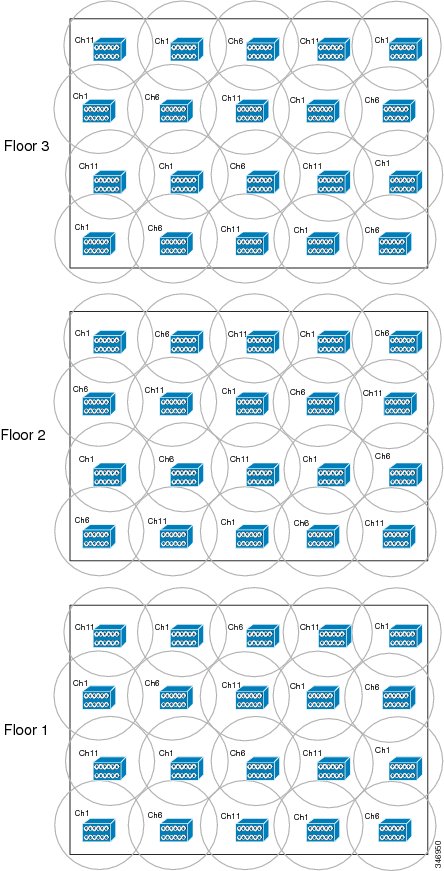
In a multifloor building, RF energy can travel between floors and, as part of RF planning, the channels are staggered from floor to floor to minimize the co-channel interference between floors, as shown in the following figure. When you consider the co-channel interference radius of an AP, you must note that the signal path between the floors is different from that on the same floor (there is often a piece of reinforced concrete in the between-floor path). You must take this into account when you consider co-channel interference radius of an AP.
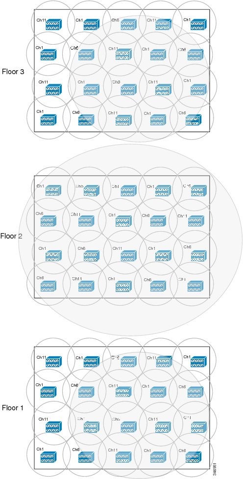
The following figure shows an example of the co-channel interference radius of APs on different floors where floor 2 is the same layout as the single-floor example, and floor 1 and floor 3 show the co-channel interference radius on the floors above and below. In the following figure, the co-channel interference between floors is still significant and it is reasonable to assume that the capacity across the three floors can be the equivalent of six or seven APs, but is not close to that of the 60 APs that are deployed.
Location-based services design considerations
The signal-level requirements of IEEE 802.11 location-based services are similar to those on RToWLAN, but the AP placement requirements are different. For example, in Figure 7, the AP placement satisfies the requirement of location-based service (LBS) deployment. In this example environment, many APs are deployed on the perimeter and at the core of the building. An additional set of APs might be required. The AP placement requirements of LBS can result in addition of more APs, depending on the shape and size of the building. The addition of more APs for LBS introduces an additional level of co-channel interference due to the additional IEEE 802.11 management traffic that is associated with additional AP. However, given the existing co-channel interference, the difference is not significant. The key point about RToWLAN deployment is that the addition of more APs do not contribute to additional capacity in the 2.4GHz band due to co-channel interference.
Auto-RF significance
The co-channel interference in the 2.4 GHz band affects the RToWLAN channel cell call capacity, and therefore you must consider this limitation while you plan, design, and operate an RToWLAN network. All the examples in this chapter assume Auto-RF is enabled, and that an AP changes channels to minimize interference and provide an optimal channel plan. With this assumption, the call capacity of the deployment is the equivalent of three times the capacity of a single AP. The auto-RF cannot do much to address the effects of co-channel interference in the 2.4 GHz channel because the limiting factor in the 2.4 GHz band is the three nonoverlapping channels. Auto-RF tunes AP power levels that can reduce co-channel interference by reducing power levels. But this power level adjustment must be balanced against the signal-level and coverage requirements of the RToWLAN deployment. It is best that you use the 5 GHz band of IEEE 802.11a standard to achieve greater capacity and a higher return on investment of the deployed APs.
IEEE 802.11a physical layer
The IEEE 802.11a standard defines the requirements for the physical layer (of the OSI model), operating in the 5 GHz unlicensed national information infrastructure (UNII) frequency band, with data rates ranging from 6 Mbps to 54 Mbps. It uses orthogonal frequency division multiplexing (OFDM), which is a multicarrier system (uses 52 subcarriers, modulated with binary phase shift keying (BPSK), quadrature phase shift keying (QPSK), quadrature amplitude modulation (QAM), or 64-QAM to provide different data rates). OFDM allows subcarrier channels to overlap thus providing high spectral efficiency. The modulation technique used by OFDM is more efficient than spread spectrum techniques that are used with IEEE 802.11b; it is the same as is used in 802.11g.
IEEE 802.11a channels
Note
For up-to-date information about what channels are supported in your country or region, see the regulatory information related to your country. In addition, not all the clients support all channels.
The following example is for the U.S.-based IEEE 802.11a standard; the 5 GHz unlicensed band covers 300 MHz of spectrum and supports 23 channels. As a result, the 5 GHz band is a conglomeration of three bands in the United States:IEEE 802.11a operating frequencies and data rates
The IEEE 802.11a standard is resistant to interference from devices that operate in the 2.4 GHz band, such as microwave ovens, cordless phones, and Bluetooth, when it operates in the unlicensed portion of the 5 GHz radio band. Because the IEEE 802.11a standard operates in a different frequency range, it is not compatible with the existing IEEE 802.11b or IEEE 802.11g-compliant wireless devices. But, it does mean that the 2.4-GHz and 5 GHz equipment can operate in the same physical environment without interference.
The IEEE 802.11a standard provides data rates of 6, 9, 12, 18, 24, 36, 48, 54 Mbps, with 54 Mbps being the maximum data rate, though generally at shorter ranges compared to 2.4 GHz network, for a given power and gain. However, it has up to 24 nonoverlapping frequency channels (depending on the geographic area) as compared to the three nonoverlapping channels for the 2.4 GHz band, which results in increased network capacity, improved scalability, and the ability to create microcellular deployments without interference from adjacent cells.
The 5 GHz band in which IEEE 802.11a operates is divided into several sub-bands. Each of the UNII bands presented in the following table were originally intended for different uses, but all can now be used for indoor IEEE 802.11a deployments with applicable power restrictions. Originally, the FCC defined the UNII-1, UNII-2, and UNII-3 bands, each consisting of four channels. The channels are spaced 20 MHz apart with an RF spectrum bandwidth of 20 MHz, thereby providing four nonoverlapping channels.
Table 3 Operating Frequency Range for IEEE 802.11a Band
Channel ID
Center Frequency
UNII-1
36
5180
40
5200
44
5200
48
5240
UNII-2
52
5260
56
5280
60
5300
64
5320
100
5500
104
5520
108
5540
112
5560
116
5580
120
5600
124
5620
128
5640
132
5660
136
5680
140
5700
UNII-3
149
5745
153
5765
157
5785
161
5805
165
5825
The limitations on each UNII bands are different such as transmit power, antenna gain, antenna styles, and usage.
- The UNII-1 band is designated for indoor operation, and initially required devices to use permanently attached antennas. The channels in this band (5.150 to 5.250 GHz) are 36, 40, 44, and 48.
- The UNII-2 band is designated for indoor or outdoor operation, and permitted the use of external antennas. The channels in this band (5.250-5.350 GHz) are 52, 56, 60, and 64, and require dynamic frequency selection (DFS) and transmitter power control (TPC). Some clients may not support all 5 GHz channels, especially UNII-2 extended channels (100-140). For more information about what channels your country supports, see the regulatory information of your country before you finalize a channel plan. Also note that not all regions support channels 120,124, and 128 (for example United Sates of America and Europe).
- The UNII-3 band, originally intended for outdoor bridge products that use external antennas, is now permitted to be used for indoor or outdoor IEEE 802.11a WLANs as well. The channels in this band are (5.725-5.825 GHz) 149, 153, 157, 161, and 165, and do not require DFS and TPC. Note that not all clients support channel 165.
- The channels in the new frequency range (5.470-5.725 GHz) are 100, 104, 108, 112, 116, 120, 124, 128, 132, 136, and 140, and require DFS and TPC.
Not all channels in a given range can be used in all of the regulatory domains. See the preceding table, which shows the various channels in the UNII-1, -2, and -3 bands, along with the additional 11 new channels.
Note
For up-to-date information about what channels are supported in your country or region, see the regulatory information related to your country.
IEEE 802.11a and RToWLAN deployments
While there are as many as 24 nonoverlapping channels in the 5 GHz band, Cisco recommends that you use the lower four and upper four channels of the 5 GHz spectrum as the base for RToWLAN, because they do not have DFS and TPC requirements. Then, determine which other channels are not affected by DFS and TPC, and add these channels to the RToWLAN base of eight channels. The timing requirements of DFS and TPC can adversely affect the RToWLAN call quality. If DFS and TPC can affect the channels in the location that you plan to deploy RToWLAN, you must select the channels appropriately. Otherwise, it is not an issue to select specific channels discretely. Ensure that the channels you select are supported by the WLAN clients (data and RToWLAN). The use of eight non-DFS channels is simpler, but every additional channel that you safely deploy increases the capacity of the design.
In addition to avoiding the DFS and TPC channels, it is also recommended that you avoid adjacent channels in the AP channel layout to avoid interference from the sidebands in each channel. The channel spacing and channel mask characteristics are such that the sidebands produced by an IEEE 802.11a client might interfere with the adjacent channels.
The general power levels and AP separation recommendations that are used in this guide for RToWLAN in the 5 GHz implementation are the same as the 2.4 GHz implementation:
- A power level boundary of ~67 dBm and a separation between adjacent AP channels of -86 dBm.
- A minimum of 20 percent overlap between nonadjacent channels is recommended for 5 GHz bands deployments.
- A 30 percent or higher overlap can still be used for dual-band deployments or for mission-critical environments.
The range in the 5 GHz band is different to that in the 2.4 GHz band. However, when you use the recommended power levels and typical antennas as mentioned in the 5 GHz band example, the obtained distances are similar to those that are used in the 2.4 GHz example. Therefore, the same AP locations and overlap are used for both 2.4 GHz and 5 GHz bands. The primary difference between the two deployments is the additional capacity that is available due to the additional nonoverlapping channels. This difference is sufficient for the 5 GHz band to be recommended for RToWLAN deployments.
Note
The TPC mechanism that is discussed in this section is different from the TPC algorithm that is part of auto-RF.
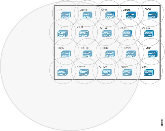
Single-floor building example
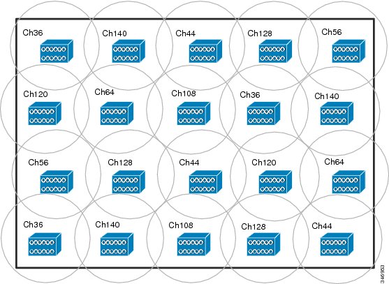
The following figure shows an AP layout that uses eight different channels that is designed to maximize the distance between reused channels. However, in most cases, the requirement is to have more channels available. Because, the 2.4 GHz and 5 GHz AP client radius and co-channel interference radii are the same in this example, the multiple floor examples are not repeated here. The major difference between the two bands is the increase in capacity that is made available by the added channels associated with the 5 GHz band. The more channels that are available for use in the 5 GHz band, the closer the capacity of the system can correlate to the number of APs that are deployed.
Note
The channels used in the preceding figure illustrates the purpose of non-overlapping channels only and is not the recommended channel layouts for any given country or region.
The following figure illustrates an example of the same AP layout as shown in the preceding figure but combined with co-channel interference radius of a single AP.
The preceding figure shows that although the co-channel interference is smaller, and more channels are available, the effect of the overall call capacity on the floor is larger. It is difficult to calculate the amount of co-channel interference across the entire floor, given that there are 20 APs and eight channels in use. Therefore, given that there are eight channels in use, the RToWLAN call capacity of the floor is equivalent to eight times the call capacity of a single AP.
Note
The channels used in the preceding figure illustrates the purpose of non-overlapping channels only and is not the recommended channel layouts for any given country or region.
Planning tools
The Cisco Unified Wireless Network Wireless Control System (WCS) provides a WLAN planning tool.
The examples that are described in this chapter use simple drawing tools and do not address the complex physical construction and building layout that you must consider for WLAN planning. It is recommended that you use WLAN planning tools to plan the WLAN layout. A small error while planning can prove to be ten times costlier to fix during layout implementation and 100 times costlier to fix during operation. The investments in planning and planning tools to design a WLAN site plan are expensive but contribute to provide maximum benefits after implementation.
Multicast over WLAN networks
Wireless LAN Controller (WLC) configuration options for multicast include changing particular multicast packets to unicast (providing reliable wireless LAN (WLAN) protocol packet delivery), creating defined multicast groups, and prioritizing packets based on application source. WLC configuration plays an important role in maintaining multicast group membership when roaming between access points (APs) or WLCs.
Multicast over WLAN presents delivery issues to Wi-Fi endpoints. These issues are not apparent or common to wired Ethernet where multicast is an effective means of preserving bandwidth on the wired network. Multicast on wireless will in many cases waste the available bandwidth on a WLAN channel if no WLC configuration options are used to manage bandwidth and delivery reliability. Because, multicast streams forwarded to an AP will be forwarded by all the enabled radios on the AP, both the 2.4 GHz and 5 GHz radios on the AP will be forwarding the multicast traffic. With default parameters in place, the multicast traffic is forwarded over the WLAN, even in cases where there are no Wi-Fi endpoints using the multicast application and receiving the multicast traffic. Unnecessary and unused multicast traffic on the Wi-Fi channels impairs the performance of the APs, clients, and the WLAN channels. Additionally, on any client VLAN locally sourced multicast traffic including multicast packets generated by protocols like Hot Standby Router Protocol (HSRP), Protocol Independent Multicast (PIM), Enterprise Interior Gateway Routing Protocol (EIGRP), and Open Shortest Path First (OSPF) will also be flooded throughout the WLAN. All this traffic is sent at the lowest broadcast data rate in use by any client associated to the particular AP potentially reducing throughput on the WLAN. As with multicast traffic on Ethernet, the Wi-Fi endpoint will not acknowledge the receipt of a multicast packet.
A prerequisite for using the multicast performance functionality is that a multicast-enabled network must be configured on all routers between the WLC and the APs. After the administrator enables multicast (multicast mode is disabled by default) and configures a CAPWAP multicast group, the APs download the controller CAPWAP multicast group address during the normal join process (at boot time). Effectively, a CAPWAP multicast group is used to deliver multicast packets to each AP. This allows the routers in the network to use standard multicast techniques to replicate and deliver multicast packets to the APs. For the CAPWAP multicast group, the WLC becomes the multicast source and the APs become the multicast receivers.
802.11n and 802.11ac protocols
The design parameters that are covered in this guide and in this chapter are applicable to the newer 802.11n and 802.11ac protocols. A cell edge of -67 dBm is still recommended with these protocols for voice and other jitter sensitive applications. These newer protocols provide greater packet speeds but WLAN usage and application resource demands have increased, so cell capacity planning is still an important aspect of WLAN coverage design.
The 802.11n and 802.11ac protocols, like their predecessors, are half-duplex radio protocols. The major difference is how much frequency is used in the transmission of a data packet. The original 802.11 specification of 1997 defined WLAN channels on 2.4 GHz. The 802.11a specification of 1999 defined the 5 GHz channels. The 802.11n specification remains compatible with both 2.4 GHz and 5 GHz bands. The 802.11n added the concept of high throughput (HT) by adding channel bonding to create cell channels with 40 MHz of frequency. 802.11n also introduced spatial streams and standards-based beamforming. The 802.11ac drops 2.4 GHz from its specification because there is not enough allocated frequency in 2.4 GHz to meet the bandwidth needs of 802.11ac. 802.11n and 802.11ac support the bonding of two or more 20 MHz 802.11 channels to provide a client or an access point with more bandwidth than previous 802.11 protocols.
An 802.11n/802.11ac bonded channel is a WLAN channel that is created by adding the frequency of other 802.11 Wi-Fi channels into a single channel that can become 80 MHz AC Wave1 or 160 MHz AC Wave2. The new 5 GHz protocol 802.11ac is going to have two hardware releases. The first generation of 802.11ac hardware is known as WAVE 1. The next release of 802.11ac hardware is known as WAVE 2. The 802.11ac specification defines a new physical (PHY) specification that provides very high throughput (VHT) based on the orthogonal frequency division multiplexing (OFDM) radio modulation system. The specification increases the number of spatial streams and provides for multi-user transmissions. WAVE 2 will provide the bonding of two 80 MHz channel into a 160 MHz channel. The 160 MHz channel can be contiguous channels or two 80+80 MHz non-contiguous channels.
802.11ac introduced support of multi-user multiple input – multiple output (MIMO) (multiple clients with spatial stream support) to transmit and receive unique data streams simultaneously. These specification enhancements have increased the throughput and bandwidth in the coverage area of the access point. Beamforming increases the AP to an individual clients performance and also increases the bandwidth on that AP WLAN channel. The MIMO antenna support at the client radio or AP radio improves transmission and reception quality. These technology improvements increase capacities in a coverage area. As with the legacy technologies of the 1990s, the AP coverage is still an important design consideration for the application performance of Wi-Fi endpoints.
802.11ac VHT PHY provides backward compatibility to 802.11n and 802.11a protocols. Therefore, a legacy 802.11a client can associate, authenticate, and pass traffic through the 802.11ac AP at the data rates that are supported on the client. Current 802.11ac APs support 4x4 MIMO technology with three spatial streams that provides transmission data rates of 1.3 Gbps.
Client device application performance in the new VHT client radio hardware is directly related to the current bandwidth of the WLAN channel. This was a condition with the legacy clients and will be a condition with the next generation of Wi-Fi protocols. Therefore, the same design criteria that is used for earlier WLAN cell design still applies. WLAN applications generally require more bandwidth, as much bandwidth as wired applications. To achieve more bandwidth in a given floor space, WLAN channels in the given floor spaces must become more efficient. This requires more efficiency on the client radio and the AP radio. This may also require configuration changes of the data rates that are assigned to the radios. Removing the 1997 data rates of 1 Mbps and 2 Mbps is highly recommended. Removing the 1999 data rates of 5.5 Mbps and 11 Mbps is also recommended when applicable. Having any of those data rates set as required is likely to impact client application performance in dense coverage area. Enabling 5 GHz is highly recommended.
Successfully deploying a WLAN network that is able to provide diverse services in a challenging environment can be a challenging project for any organization. Doing it right the first time requires a special set of skills and knowledge that sometimes is difficult to find. Partnering with a network integrator that is experienced with wireless deployments can be very beneficial.
The 802.11ac specification is supported by the AP3600 with and 802.11ac module and the AP3700. Current radio technology supports 80 MHz wide channels but not multi-user transmissions or 160 MHz wide channels.