Table Of Contents
Metro Ethernet Service Framework
Relationship between Service Multiplexing, Bundling, and All-to-One Bundling
Ethernet Relay Multipoint Service
Metro Ethernet Services
Metro Ethernet Service Framework
This chapter describes the typical Metro Ethernet Services available from service providers (SPs). For the most part, these services are derived from and map to the following Metro Ethernet Forum (MEF) specifications:
•
MEF 6, Ethernet Services Definitions—Phase 1, June 2004
•
Note
These MEF technical specifications describe the attributes and associated parameters that define specific Ethernet services. They also provide a framework for characterizing Ethernet services, which can be used by SPs in their deployments, or by design and sales engineers in responding to SP request for proposals (RFPs).
Following the MEF approach, the services that comprise the Metro Ethernet (ME) solution can be classified into the following two general categories:
•
•
In the MEF terminology, this maps to the following Ethernet service types:
•
•
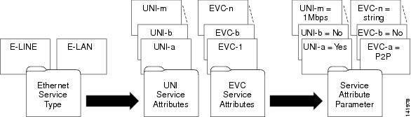
Within these two service types, Metro Ethernet services can be created by assigning values to a set of attributes grouped according to the following:
•
•
Figure 6-1 illustrates the service definition framework described above.
Figure 6-1 Metro Ethernet Framework
MEF Services
MEF 6 defines two examples of E-Line services:
•
•
As of publication of this document, the MEF has not yet defined multipoint services. However, a multipoint service type (E-LAN) does exist.
See Table 6-1 for a mapping of the above services with Cisco terminology.
Metro Ethernet Services
Before discussing ME services, note the following two definitions.
•
•
ME services consist of various types of UNIs that are used in combination with EVCs, which can be built over Layer 1, Layer 2, or Layer 3 networks. This section provides a brief summary of these services, which are subsequently described in more detail:
•
•
•
•
•
•
•
The ME services map to the MEF services (and service types in case of undefined services) described in Table 6-1
.
Table 6-1 MEF to Cisco Metro Ethernet Services Mapping
EWS
EPL
ERS
EVPL
EPL
EPL
EMS
E-LAN service type
ERMS
E-LAN service type
These Metro Ethernet services are then defined by assigning specific attributes for the UNIs and EVCs. They are characterized by associating parameters to the attributes. The following sections describe the attributes for the EVC and UNI.
EVC Service Attributes
An EVC allows Ethernet service frames to be exchanged between UNIs that are connected via the same EVC. Some frames are subscriber data service frames while others are Ethernet control service frames. The following attributes describe the EVC:
•
•
•
–
–
–
Note
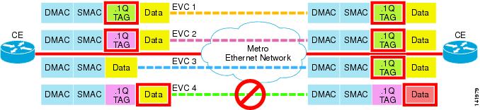
Figure 6-2 shows three possible cases (EVC 1 through EVC 3) of EVCs with service transparency, as well as a case (EVC 4) where service frame transparency is not achieved:
•
•
•
•
Figure 6-2 Service Frame Transparency EVC Attribute
•
Note
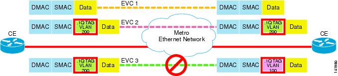
Figure 6-3 CE-VLAN ID Preservation EVC Attribute
•
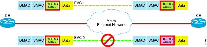
Figure 6-4 CE-VLAN CoS Preservation EVC Attribute
•
•
•
•
•
–
–
–
•
–
–
–
–
Table 6-2 summarizes the EVC attributes as defined generically in MEF 10, Ethernet Services Attributes, Phase 1 standard.
Table 6-2 Summary of MEF EVC Service Attributes
EVC type
Point-to-point or multipoint-to-multipoint
UNI list
A list of UNI identifiers
Service frame transparency
Yes or no
CE-VLAN ID preservation
Yes or no
CE-VLAN CoS preservation
Yes or no
Unicast service frame delivery
Discard, deliver unconditionally, or deliver conditionally. If deliver conditionally is used, then the conditions must be specified.
Multicast service frame delivery
Discard, deliver unconditionally, or deliver conditionally. If deliver conditionally is used, then the conditions must be specified.
Broadcast service frame delivery
Discard, deliver unconditionally, or deliver conditionally. If deliver conditionally is used, then the conditions must be specified.
Class of service identifier
<EVC>, <EVC, DSCP>, or <EVC, COS>
EVC performance
Frame delay
Frame delay variation
Frame loss
Bridge block of protocols:
0x0180.C200.0000 through 0x0180.C200.000F
Discard or tunnel
GARP block of protocols:
0x0180.C200.0020 through 0x0180.C200.002F
Discard or tunnel
All bridges protocol
0x0180.C200.0010
Discard or tunnel
1 Note that SPs may define additional addresses as Layer 2 control in addition to those listed here.
ME EVC Service Attributes
Table 6-3 summarizes the EVC service attributes for each of the ME services. Note that not all of the MEF attributes are listed in this table (attributes used for record-keeping/inventory purposes have been omitted). Also, because the L2 control protocol processing for the ME services happens at the UNI, those attributes are not included for the EVC.
Table 6-3 ME EVC Service Attributes
EVC type
PtP
MPtMP
PtP
MPtMP
PtP
Service frame transparency1
Yes2
Yes
Yes
Yes
Yes
CE-VLAN ID preservation
Yes3 or No
Yes4 or No
Yes
Yes
Yes
CE-VLAN CoS preservation
No5
No6
Yes
Yes
Yes
Unicast7 frame delivery
Deliver un- conditionally
Deliver un- conditionally
Deliver un- conditionally
Deliver un- conditionally
Deliver un- conditionally
Multicast frame delivery
Deliver conditionally per threshold
Deliver conditionally per threshold
Deliver conditionally per threshold
Deliver conditionally per threshold
Deliver un- conditionally
Broadcast frame delivery
Deliver conditionally per threshold
Deliver conditionally per threshold
Deliver conditionally per threshold
Deliver conditionally per threshold
Deliver un- conditionally
Class of service identifier
EVC
<EVC, DSCP>
<EVC, CoS>8
EVC
<EVC, DSCP>
<EVC, CoS>9
EVC
<EVC, CoS>10
EVC
<EVC, CoS>11
EVC
EVC performance
For each CoS instance, specify the frame delay, frame delay variation, and frame loss
1 This is a mandatory attribute for all Layer 2 services of the solution.
2 In some cases, where an ERS is used as an Ethernet local loop for L3 services such as Ethernet Internet Access (EIA), SPs have expressed interest in changing customer DSCP values (typically to zero (0)).
3 The CE-VLAN ID preservation attribute can be achieved for ERS/ERMS services with the use of the 1:1 VLAN Mapping feature.
4 Same as above.
5 CE-VLAN CoS preservation for ERS/ERMS (that is, when at most only a single 802.1Q tag is present) is only possible if: a) SP employs a restricted and direct mapping from authorized CE-VLAN CoS values to SP-VLAN CoS. b) SP directly maps ingress CE-VLAN CoS to MPLS EXP in cases where the UNI resides at the MPLS PE device.
6 Same as above.
7 Assumes that the unicast traffic conforms to the service policy.
8 The <EVC, CoS> CoS identifier for ERS/ERMS is a new capability for the ME solution.
9 Same as above.
10 The <EVC, CoS> CoS identifier for EWS/EMS is a new capability for ME solution. This requires CE-VLAN CoS inspection to derive the SP-VLAN CoS value.
11 Same as above.
UNI Service Attributes
A UNI can have a number of characteristics that influence the way the Customer Edge (CE) device sees a service. The UNI service attributes are as follows:
•
•
•
•
•
•
•
Note
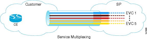
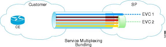
•
•
–
Figure 6-5 Service Multiplexed UNIs that Support Multiple EVCs
•
–
–
Figure 6-6 Bundling Attribute on a UNI
.
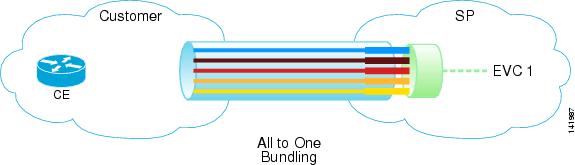
•
–
–
Figure 6-7 All-to-One Bundling UNI Attribute
•
–
–
–
Each bandwidth profile consists of the following parameters:
•
•
•
•
Note
•
Table 6-4 provides a summary of the MEF UNI attributes as defined generically in MEF 10, Ethernet Services Attributes, Phase 1 standard.
.
Table 6-4 Table Summary of MEF UNI Attributes
UNI identifier
Any string
Physical medium
A standard Ethernet PHY1
Speed
10 Mbps, 100 Mbps, 1 Gbps, or 10 Gbps
Mode
Full Duplex or Auto negotiation
MAC Layer
802.3-2002
UNI EVC ID
An arbitrary string for the EVC supporting the service instance
CE-VLAN ID/EVC map
Mapping table of CE-VLAN IDs to EVCs at the UNI
Maximum number of EVCs
An integer greater than or equal to 1
Service multiplexing
Yes or no
Bundling
Yes or no
All-to-one bundling
Yes or no
Ingress bandwidth profile per ingress UNI
No or <CIR, CBS, PIR, PBS>
Ingress bandwidth profile per EVC
No or <CIR, CBS, PIR, PBS>
Ingress bandwidth profile per Class of Service identifier
No or <CIR, CBS, PIR, PBS>
Bridge block of protocols:
0x0180.C200.0000 through 0x0180.C200.000F
Discard, peer, or pass to EVC
GARP block or protocols:
0x0180.C200.0020 through 0x0180.C200.002F
Discard, peer, or pass to EVC
All bridges protocol
0x0180.C200.0010
Discard, peer, or pass to EVC
1 Per IEEE P 802.3-2002.
2 Note that SPs may define additional addresses as Layer 2 control in addition to those listed here.
)
Relationship between Service Multiplexing, Bundling, and All-to-One Bundling
Table 6-5 shows the valid combinations for three of the most relevant UNI attributes highlighted in the previous section. Some are mutually exclusive and therefore only some combinations are allowed. For example, if a UNI exhibits the all-to-one bundling attribute, service multiplexing and bundling must not be present.
Table 6-5 UNI Attribute Valid Combinations
Service multiplexing
Yes
Yes
No
Bundling
No
Yes
No
All-to-one bundling
No
No
Yes
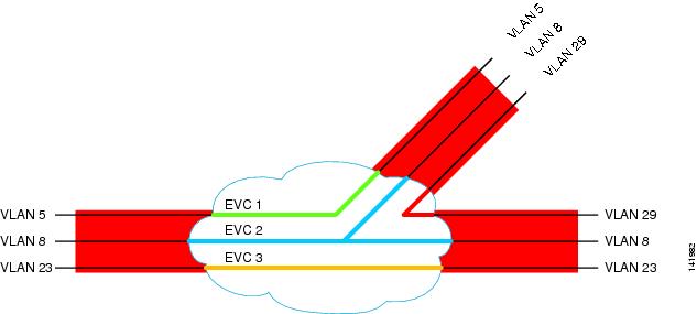
Figure 6-8 through Figure 6-10 support the content of the previous table and show three UNIs with the allowed attribute combination. Observe that in these examples, UNIs are receiving service frames from five (5) CE-VLAN IDs.
In the first scenario, each CE-VLAN ID is mapped to one EVC for a total of five (5) EVCs at the UNI (also known as one-to-one mapping). This UNI only has the service multiplexing attribute.
Figure 6-8 Option 1—UNI with Service Multiplexing Attribute
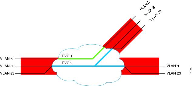
In the following example, (UNI with bundling and service multiplexing attributes), the first CE-VLAN ID is mapped to one EVC and the remaining four (4) to a second EVC. As seen, this UNI contains only two (2) EVCs.
Figure 6-9 Option 2—UNI with Bundling and Service Multiplexing Attributes
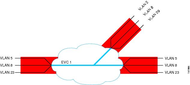
Lastly, the last UNI highlights the case where all CE-VLAN IDs are mapped to just one EVC. In this case, the UNI has the all-to-one bundling attribute.
Figure 6-10 Option 3—UNI with All-to-One Bundling Attribute
ME UNI Service Attributes
Table 6-6 summarizes the UNI service attributes for each of the ME services. Note that not all of the MEF attributes are listed in this table (attributes used for record-keeping/inventory purposes have been omitted). Also, the table expands the Layer 2 control processing section from the one included in MEF 10.
Table 6-6 ME UNI Service Attributes
Speed
10/100/1000 Mbps
MAC layer
IEEE 802.3-2002
Service multiplexing
Yes
Yes
Yes1 or No
Yes2 or No
No
Bundling
No3
No4
Yes5 or No
Yes6 or No
No
All-to-one bundling
No
No
No or Yes
No or Yes
Yes
Maximum number of EVCs
>=1
>=1
>=17
>=18
== 1
Ingress bandwidth profile per UNI
No or <CIR, CBS, EIR, EBS>9
No or:
CIR > 0, CBS > largest frame size
PIR == 0, PBS == 0
Ingress bandwidth profile per EVC
No or <CIR, CBS, EIR, EBS>10
n/a
Ingress and egress bandwidth profile per CoS identifier
No or <CIR, CBS, EIR, EBS>11
n/a
802.3x handling
Discard
Discard
Discard
Discard
Discard
LACP handling
Discard
Discard
Pass to EVC
Discard
Pass to EVC
802.1x handling
Discard
Discard
Discard
Discard
Pass to EVC
GARP handling
Discard
Discard
Discard
Discard
Pass to EVC
STP handling
Discard
Discard
Pass to EVC
Pass to EVC
Pass to EVC
Protocol that multicasts to all bridges in a bridged LAN
Discard
Discard
Discard
Discard
Pass to EVC
CDP handling
Discard
Discard
Pass to EVC
Pass to EVC
Pass to EVC
VTP handling
Discard
Discard
Pass to EVC
Pass to EVC
Pass to EVC
PAgP handling
Discard
Discard
Pass to EVC
Discard
Pass to EVC
UDLD handling
Discard
Discard
Pass to EVC
Discard
Pass to EVC
1 Service multiplexing on a UNI with an EWS/EMS service is optional and is achieved when the bundling UNI attribute is present. In this case, the all-to-one bundling attribute must be No.
2 Same as above.
3 ERS/ERMS services are defined with a one-to-one relationship for the CE-VLAN ID/EVC map attribute (that is, one EVC maps to no more than one CE-VLAN ID). Therefore, the UNI bundling attribute may exist at the UNI but is not associated with the corresponding EVC for the mentioned services.
4 Same as above.
5 Bundling may be present on a UNI with an EWS/EMS service. If present, the all-to-one bundling attribute must be No.
6 Same as above.
7 With the presence of the bundling attribute at the UNI, it is possible to have more than one service in a UNI that holds an EWS/EMS service.
8 Same as above.
9 Ingress BW profile per UNI is mostly applied on cases where the UNI holds a single EVC. The ability to support CIR/PIR depends mostly on the U-PE capabilities. Certain services (for example, multipoint) might be offered with CIR == 0.
10 Ability to support CIR/PIR depends mostly on the U-PE capabilities. Certain services (or example, multipoint) might be offered with CIR == 0 .
11 Ability to support CIR/PIR and <EVC, CoS> or <EVC, DSCP> CoS IDs depends mostly on the U-PE capabilities. Certain services (or example, multipoint)) might be offered with CIR == 0.
Ethernet Relay Service
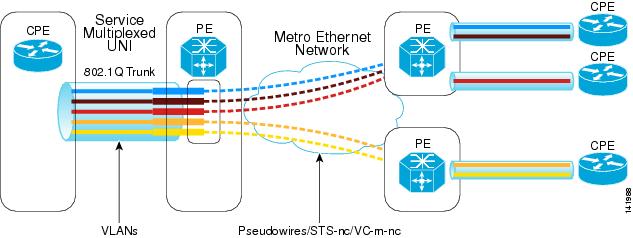
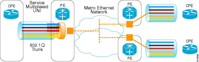
ERS is an Ethernet point-to-point VLAN-based service targeted to Layer 3 CEs (routers). Among its applications, ERS represents a high-speed alternative to existing Frame Relay and ATM offerings. For example, the VLANs in Figure 6-11 can be considered equivalent to DLCIs in FR circuits that carry the traffic from a corporate office to the regional office sites.
Figure 6-11 ERS Deployment Scenario—Multiple ERS Multiplexed Over a Single UNI Interface
Note
The ERS UNI is typically an 802.1Q trunk (or access port) that allows the SP to multiplex services on a single interface. This gives the SP the capability to direct customer traffic to different destination routers using the appropriate VLAN IDs.
When ERS is implemented over an MPLS core, there is a one-to-one mapping between 802.1Q VLAN IDs and EoMPLS pseudowires.
As mentioned earlier, the intended termination device of this service is a Layer 3 CE. Thus, ERS purposely does not tunnel Layer 2 control PDUs (for example, STP BPDUs, VTP) typically exchanged by Layer 2 CEs (bridges). With the selection of a Layer 3 CE, the SP reduces the number of MAC addresses that need to be learned by the network (that is, only two MACs per VLAN for a point-to-point service).
Note
Ethernet Wire Service
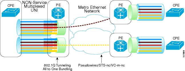
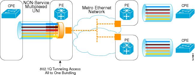
EWS is an Ethernet point-to-point port-based service targeted to Layer 2 CEs (bridges). Among its main applications, this service can be used to connect geographically remote LANs over an SP network.
Figure 6-12 EWS Deployment Scenario—Two Services Provisioned Over the SP Network
When implemented on Cisco Catalyst switches, the EWS UNI is an 802.1Q tunnel (or QinQ) interface, which allows the SP to tunnel any number of CE-VLANs through the SP network. This is accomplished by encapsulating customer traffic inside a pre-defined SP VLAN, thus allowing overlapping customer VLAN IDs. In MEF terms, a UNI of these characteristics is described as supporting the all-to-one bundling UNI attribute.
Note that an 802.1Q tunnel increases the supported number of customer VLANs. Therefore, it is possible to support 4094 customers per Metro access domain, where each UNI could potentially receive up to 4094 VLANs per customer.
Because the service is intended for Layer 2 CEs, VLAN transparency and Layer 2 PDU transparency are key characteristics provided by it. One of the ways to achieve VLAN transparency is with the QnQ behavior described in the previous paragraph. Secondly, Layer 2 PDU (for example, STP, VTP) transparency can be achieved with the use of features such as Layer 2 Protocol Tunneling (L2PT), which effectively makes the remote LANs appear as if they were on the same segment (from a control plane perspective). An example of an EWS is shown in Figure 6-12.
Note
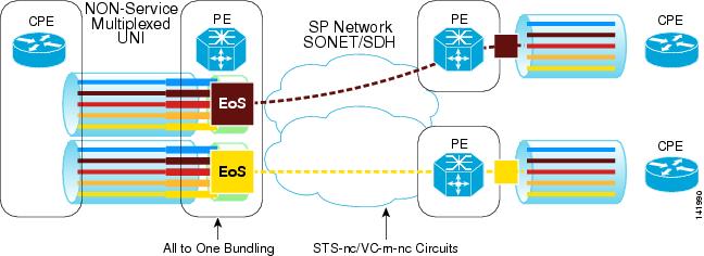
Ethernet Private Line
EPL is an Ethernet point-to-point, port-based service that maps customer Layer 2 traffic directly onto a TDM circuit. It is considered by US-based SP transport/transmission groups as the alternative to offer a "private" service. With an EPL, the customer Ethernet stream is encapsulated directly into the SONET or SDH frame and mapped exclusively onto an STS or VC circuit. From a service attribute perspective, EPL is a VLAN and L2PDU transparent service that supports all-to-one bundling, but not service multiplexing.
Figure 6-13 illustrates a sample EPL service offering.
Figure 6-13 EPL Deployment Scenario
Ethernet Multipoint Service
EMS is an Ethernet multipoint-to-multipoint port-based service targeted to Layer 2 CEs (bridges). It is used primarily for transparent LAN service applications.
For the most part, EMS and EWS share the same service characteristics. Their main difference is that EMS is a multipoint-to-multipoint service. See Ethernet Wire Service for a basic description of this service.
When implemented over MPLS, the SP VLAN is mapped to a virtual private LAN service (VPLS) forwarding instance (VFI). Figure 6-14 illustrates a sample EMS.
Figure 6-14 EMS Deployment Scenario for Three Customer Sites
ME EMS Enhancement
EMS enjoys the same service enhancements as EWS.
Ethernet Relay Multipoint Service
ERMS is an Ethernet multipoint-to-multipoint VLAN-based service targeted to Layer 3 CEs (routers). It is intended for scenarios where customers desire a multipoint-to-multipoint connection among WAN routers.
For the most part, ERMS and ERS share the same service characteristics. Their main difference is that ERMS is a multipoint-to-multipoint service. See Ethernet Relay Service for a basic description of this service.
When implemented over MPLS, the SP VLAN is mapped to a virtual private LAN service (VPLS) VFI. Figure 6-15 illustrates a sample ERMS.
Figure 6-15 ERMS Deployment Scenario