Table Of Contents
Configurations for Layer 2 Extension with EoMPLS
Configuring the Loopback Interface
Aggregation Switch Right (Catalyst 6000 Series Switch-Sup720-B)—Data Center 1
Configuring the Loopback Interface
Configuring Interface fa5/1 (Connected to a Remote Catalyst 6000 Series Switch)
Aggregation Switch Left (Catalyst 6000 Series Switch-Sup720-B)— Data Center 2
Configuring the Loopback Interface
Aggregation Switch Right (Catalyst 6000 Series Switch-Sup720-B)— Data Center 2
Configuring the Loopback Interface
Configuring Interface G5/1 (Connected to Remote Catalyst 6000 Series Switch)
Data Center 1 (Catalyst 6000 Series Switch—DC1-Left)
Data Center 1 (Catalyst 6000 Series Switch—DC1-Right)
Data Center 2 (Catalyst 6000 Series Switch—DC2-Left)
Data Center 2 (Catalyst 6000 Series Switch—DC2-Right)
Configurations for Layer 2 Extension with EoMPLS
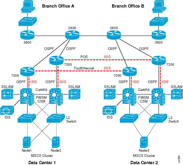
The tested architecture is based on two fully redundant data centers (DC1 and DC2) and two remote branch offices, all connected to a WAN access network built with 2 x 2600 routers. An MPLS network is built between the two data centers with the WAN access router (7200), as shown in Figure A-1.
Figure A-1 Corporate Data Centers and Branch Offices
For this test setup, a Microsoft MSCS cluster is built with three nodes, two nodes located on DC1 and a third node located on DC2. The cluster requires two distinct Layer 2 networks between each node. Each node is configured with two NICs, one used for the cluster heartbeat and one dedicated for the VIP (user access). Each interface is connected to a dedicated VLAN: VIP belongs to VLAN 601 and HB (heartbeat) belongs to VLAN 602.
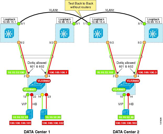
Figure A-2 Layer 2 Back-to-Back Testing
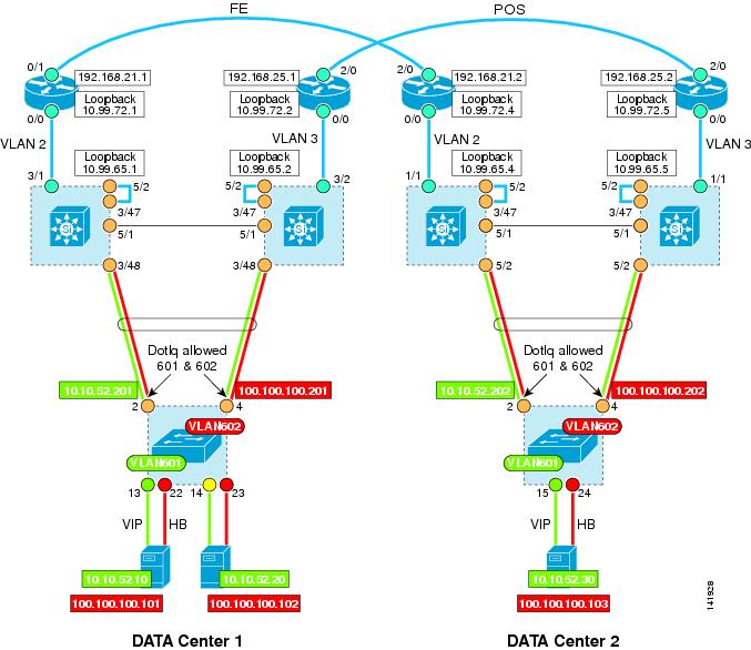
With Option 3, the Layer 2 VPN tunnel built with the Port-based Xconnect is initiated directly at the interface that connects to the access switch. With this design, the EoMPLS tunnel (pseudowire) is transparent to the access switch (see Figure A-3). Therefore, the EtherChannel feature might be useful to deploy, as an alternative to spanning tree.
However, deploying EoMPLS in native IOS (with no additional OSM or SIP card) does not allow switching the internal VLAN coming from the access switch to outside the Layer 2 tunnel. Therefore, an additional parallel physical link must be provisioned from the access switch to the aggregation switch to allow required VLANs to be routed outside the data center, such as the VLAN 601 used for the VIP of the cluster, or, in these tests, the VLAN 1 used for management purposes.
Figure A-3 Port-Based Xconnect with with Multiple Links from the Access Switches
As described in the previous configuration, Option 3 requires two parallel links between the aggregation and the access layers to be able to route the VLAN outside the pseudowires.
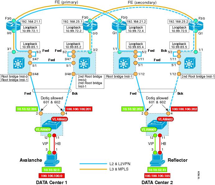
An alternative design to using additional links from the access switches consists in using a loopback cable, also referred to as Option 4 in this guide (see Figure A-4.)
Figure A-4 Port-Based Xconnect Using Loopback Cable
To use the loopback cable, a full trunk is created between the access switch and the aggregation switch on both interfaces. As you recall, with Option 3, only the interface on the access switch is using the mode trunk, the interface on the aggregation switch is configured in access mode for the pseudowire.
On this test, the interfaces n/48 are configured using the mode trunk allowing VLAN 601 (VIP), VLAN 602 (heartbeat) and VLAN 1 (management). Therefore, any of these VLANs can be routed by the MSFC as any traditional SVI.
For the pseudowire, an additional interface (n/47) is created in trunk mode and allowed the VLAN 601 and 602 for the Layer 2 tunnel. A loopback cable was added to interconnect interface n/47 to an interface used for the Port-based Xconnect interface (pseudowire) G5/2.
Configurations
Enabling MPLS
!mpls label protocol ldpmpls ldp router-id Loopback99mpls ldp neighbor 10.99.65.2 targeted ldp ! to maintain label binding even on link failurempls ldp neighbor 10.99.72.1 targeted ldpno mpls ldp advertise-labels ! to limit advertisement of label to EoMPLS loopbacksmpls advertise-tags for 1 ! ...access-list 1 permit 10.99.0.0 0.0.255.255 ! ...!Port-based Xconnect
Interface G5/2 cannot be configured as a switchport. As it receives tagged frames (+4 bytes), the MTU must be increased to 1504 (4 Bytes dot1Q). The interface xconnect to the remote loopback uses encapsulation MPLS.
!interface GigabitEthernet5/2mtu 1504no ip addressload-interval 30media-type rj45xconnect 10.99.65.4 100 encapsulation mpls!Configuring the Loopback Interface
!interface Loopback99ip address 10.99.65.1 255.255.255.255ip router isisisis circuit-type level-1!Configure VLAN 2 to interconnect both data centers. The same VLAN ID is used for both Catalyst 6000 Series switches. ISIS is configured with MPLS. The minimum MTU size for VLAN 2 must be set to 1522 (802.3 max frame size 1518 + 4 bytes for tagged frames). The uplinks from the access switch carry multiple VLANs to the aggregation switch where the uplink interface is configured in access mode. This means that any tagged frames from the access switch are seen as a raw larger frames.
!interface Vlan2mtu 1522ip address 10.0.0.2 255.255.255.252ip router isistag-switching iptag-switching mtu 1526isis circuit-type level-1isis hello-multiplier 10 level-1isis hello-interval minimal level-1!Configure the interface fa6/1 that belongs to VLAN 2 and connected to the remote Catalyst 6000 Series switch. Note that the MTU is forced to 9216.
!interface FastEthernet6/1switchportswitchport access vlan 2switchport mode accessmtu 9216no ip addressload-interval 30spanning-tree portfast!Configuring OSPF
!router ospf 1log-adjacency-changesredistribute static subnetsnetwork 10.0.0.0 0.0.0.3 area 0network 10.0.2.0 0.0.0.255 area 0network 10.0.10.0 0.0.0.255 area 0network 10.0.20.0 0.0.0.255 area 0network 10.0.30.0 0.0.0.255 area 0network 10.0.40.0 0.0.0.255 area 0network 10.0.51.0 0.0.0.255 area 0!Configuring ISIS
!router isisnet 49.0001.0000.6500.1111.00is-type level-1metric-style widepassive-interface Loopback99advertise passive-onlyspf-interval 20 100 20prc-interval 20 100 20lsg-gen-interval 1 1 20fast-flood 15!Aggregation Switch Right (Catalyst 6000 Series Switch-Sup720-B)—Data Center 1
Enabling MPLS
!mpls label protocol ldpmpls ldp router-id Loopback99mpls ldp neighbor 10.99.65.1 targeted ldpmpls ldp neighbor 10.99.72.2 targeted ldpno mpls ldp advertise-labelsmpls advertise-tags for 1access-list 1 permit 10.99.0.0 0.0.255.255!Port-based Xconnect
!interface GigabitEthernet5/2no ip addressmtu 1504load-interval 30media-type rj45xconnect 10.99.65.5 100 encapsulation mpls!!Configuring the Loopback Interface
!interface Loopback99ip address 10.99.65.2 255.255.255.255ip router isisisis circuit-type level-1!Configuring VLAN 2
!interface Vlan2mtu 1522ip address 10.10.0.2 255.255.255.252ip router isistag-switching iptag-switching mtu 1526isis circuit-type level-1isis hello-multiplier 10 level-1isis hello-interval minimal level-1!Configuring Interface fa5/1 (Connected to a Remote Catalyst 6000 Series Switch)
!interface GigabitEthernet5/1mtu 9216switchportswitchport access vlan 2switchport mode accessno ip addressload-interval 30spanning-tree portfast!Configuring OSPF
!router ospf 1log-adjacency-changesredistribute static subnetsnetwork 10.0.0.0 0.0.0.3 area 0network 10.0.2.0 0.0.0.255 area 0network 10.0.10.0 0.0.0.255 area 0network 10.0.20.0 0.0.0.255 area 0network 10.0.30.0 0.0.0.255 area 0network 10.0.40.0 0.0.0.255 area 0!Configuring ISIS
!router isisnet 49.0001.0000.6500.2222.00is-type level-1metric-style widepassive-interface Loopback99advertise passive-onlyspf-interval 20 100 20prc-interval 20 100 20lsg-gen-interval 1 1 20fast-flood 15!Aggregation Switch Left (Catalyst 6000 Series Switch-Sup720-B)— Data Center 2
Enabling MPLS
!mpls label protocol ldpmpls ldp router-id Loopback99mpls ldp neighbor 10.99.65.5 targeted ldpmpls ldp neighbor 10.99.72.4 targeted ldpno mpls ldp advertise-labelsmpls advertise-tags for 1access-list 1 permit 10.99.0.0 0.0.255.255!Port-based Xconnect
Interface G5/2 cannot be configured as a switchport. As it receives tagged frames (+4 bytes), the MTU must be increased to 1504. The interface Xconnect to the remote loopback using encapsulation MPLS.
!interface GigabitEthernet5/2description "to access switch Xconn"mtu 1504no ip addressload-interval 30no mdix autoxconnect 10.99.65.1 100 encapsulation mpls!Configuring the Loopback Interface
!interface Loopback99ip address 10.99.65.4 255.255.255.255ip router isisisis circuit-type level-1!Configure VLAN 2 to interconnect both data centers. The same VLAN ID is used for both Catalyst 6000 Series switches. ISIS is configured with MPLS.
!interface Vlan2mtu 1522ip address 10.0.0.1 255.255.255.252ip router isistag-switching iptag-switching mtu 1526isis circuit-type level-1isis hello-multiplier 10 level-1isis hello-interval minimal level-1!Configure the interface fa1/1 that belongs to VLAN 2 and connected to the remote Catalyst 6000 Series switch. Note that the MTU is forced to 9216.
!interface FastEthernet1/1description To-router-rack1switchportswitchport access vlan 2switchport mode accessmtu 9216no ip addressload-interval 30spanning-tree portfastlan-name Router-L!Configuring OSPF
!router ospf 1log-adjacency-changesredistribute static subnetsnetwork 10.10.0.0 0.0.0.3 area 0network 10.10.2.0 0.0.0.255 area 0network 10.10.10.0 0.0.0.255 area 0network 10.10.20.0 0.0.0.255 area 0network 10.10.30.0 0.0.0.255 area 0network 10.10.50.0 0.0.0.255 area 0!Configuring ISIS
!router isisnet 49.0001.0000.6500.4444.00is-type level-1metric-style widepassive-interface Loopback99advertise passive-onlyspf-interval 20 100 20prc-interval 20 100 20lsg-gen-interval 1 1 20fast-flood 15!Aggregation Switch Right (Catalyst 6000 Series Switch-Sup720-B)— Data Center 2
Enabling MPLS
!mpls label protocol ldpmpls ldp router-id Loopback99mpls ldp neighbor 10.99.65.4 targeted ldpmpls ldp neighbor 10.99.72.5 targeted ldpno mpls ldp advertise-labelsmpls advertise-tags for 1access-list 1 permit 10.99.0.0 0.0.255.255!Port-based Xconnect
!interface GigabitEthernet5/2description "to access switch Xconn"mtu 1504no ip addressload-interval 30media-type rj45xconnect 10.99.65.2 100 encapsulation mplslan-name Cluster!!Configuring the Loopback Interface
!interface Loopback99ip address 10.99.65.5 255.255.255.255ip router isisisis circuit-type level-1!Configuring VLAN 2
!interface Vlan2mtu 1522ip address 10.10.0.1 255.255.255.252ip router isistag-switching iptag-switching mtu 1526isis circuit-type level-1isis hello-multiplier 10 level-1isis hello-interval minimal level-1!Configuring Interface G5/1 (Connected to Remote Catalyst 6000 Series Switch)
!interface GigabitEthernet5/1mtu 9216switchportswitchport access vlan 2switchport mode accessno ip addressload-interval 30spanning-tree portfast!Configuring OSPF
!router ospf 1log-adjacency-changesredistribute connectedredistribute static subnetsnetwork 10.10.0.0 0.0.0.3 area 0network 10.10.2.0 0.0.0.255 area 0network 10.10.10.0 0.0.0.255 area 0network 10.10.20.0 0.0.0.255 area 0network 10.10.30.0 0.0.0.255 area 0network 10.10.50.0 0.0.0.255 area 0!Configuring ISIS
!router isisnet 49.0001.0000.6500.5555.00is-type level-1metric-style widepassive-interface Loopback99advertise passive-onlyspf-interval 20 100 20prc-interval 20 100 20lsg-gen-interval 1 1 20fast-flood 15!MTU Considerations
The interface Xconnect receives tagged frames from all VLANs created at the access switches (601 and 602 in this example). Therefore, 4 bytes must be added to the Interface MTU (here Gig5/2).
The VLAN connecting the Catalyst 6000 Series switch to the edge router should support 1518 bytes (max Ethernet frame size) + 4 bytes, or 1522 bytes (VLAN 2 in this example).
Also, the physical Interface that connects to the remote router must use a bigger MTU. The minimum MTU size for the egress interface is 9216 (Int Gig5/1 in this example).
Spanning Tree Configuration
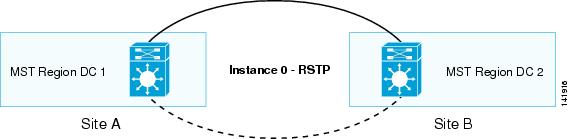
The design uses MST as Spanning Tree Protocol. Each data center is aggregated within a dedicated MST region. Therefore, between the two MST regions, RSTP is enabled to carry the BPDU for the Instance 0 (default). (See Figure A-5.)
This assumes the following:
•
The root bridge for Instance 0 is located on the DC1 left Catalyst 6000 Series switch.
•
MST Region 1:
•
–
•
MST Region 2:
•
–
•
Figure A-5 Global Test Layer 2 Site-to-Site
MST Configuration
By default, all switches use the same cost for the gigabit Ethernet interfaces (20000). The MST region appears as a logical bridge from outside. The two MST regions can be conceived as two logical bridges connected, as shown in Figure A-6.
Figure A-6 MST Configuration
Assuming the root bridge for Instance 0 is on site A (DC1 in this test), the spanning tree for the logical switch on site B (DC2) activates only one link to reach the remote switch (normal STP behavior to prevent any Layer 2 looping). This is computed based on the Port Cost. If the Port Costs are equal, then the lowest Port ID wins. Here, within the MST, there are two physical switches. Therefore, the Port ID cannot be taken into consideration to compute the forwarding path, and MST uses the lowest MAC address to enable the forwarding path to the root bridge located on the remote site.
As previously stated, it was decided to use the left switches of DC1 (Catalyst 6000 Series switch-DC1-Left) to be the root bridge for IST-0. Unfortunately, the lowest Bridge ID of the Catalyst 6000 Series switch in DC2 is the Catalyst 6000 Series switch-DC2-Right. Therefore, the forwarding link to DC1 is on Catalyst 6000 Series switch-DC2-Right, the edge interface of the Catalyst 6000 Series switch-DC2-Left being backup for the remote DC1.
To position the STP path where desired for this test, the port cost of the edge interface G1/11 of the Catalyst 6000 Series switch-DC2-Right is increased by one, as follows:
Cat6k-DC2-right#sho span mst 0 Before any change###### MST00 vlans mapped: noneBridge address 0011.5de0.0c00 priority 32768 (32768 sysid 0)Root address 0005.dce7.1440 priority 32768 (32768 sysid 0)port Gi1/11 path cost 20000IST master this switchOperational hello time 2, forward delay 15, max age 20Configured hello time 2, forward delay 15, max age 20, max hops 20Interface Role Sts Cost Prio.Nbr Type---------------- ---- --- --------- -------- --------------------------------Gi1/11 Root FWD 20000 128.11 P2p Bound(RSTP)Gi1/12 Desg FWD 20000 128.12 P2pPo10 Desg FWD 20000 128.1665 P2pPo259 Desg FWD 5000 128.1667 Edge P2pCat6k-DC2-right#conf tEnter configuration commands, one per line. End with CNTL/Z.Cat6k-DC2-right(config)#inter g1/11Cat6k-DC2-right(config-if)#span cost 20001 default = 20000Cat6k-DC2-right#sho span mst 0###### MST00 vlans mapped: noneBridge address 0011.5de0.0c00 priority 32768 (32768 sysid 0)Root address 0005.dce7.1440 priority 32768 (32768 sysid 0)port Po10 path cost 20000IST master address 0012.449a.5000 priority 32768 (32768 sysid 0)path cost 20000 rem hops 19Operational hello time 2, forward delay 15, max age 20Configured hello time 2, forward delay 15, max age 20, max hops 20Interface Role Sts Cost Prio.Nbr Type---------------- ---- --- --------- -------- --------------------------------Gi1/11 Altn BLK 20001 128.11 P2p Bound(RSTP)Gi1/12 Desg LRN 20000 128.12 P2pPo10 Root FWD 20000 128.1665 P2pPo259 Desg FWD 5000 128.1667 Edge P2pCat6k-DC1-left#sho span mst confName [DC1]Revision 10Instance Vlans mapped-------- ---------------------------------------------------------------------0 none1 601-6022 1-600,603-4094-------------------------------------------------------------------------------Cat6k-DC1-left#sho span mst 0###### MST00 vlans mapped: noneBridge address 0005.dce7.1440 priority 32768 (32768 sysid 0)Root this switch for CST and ISTConfigured hello time 2, forward delay 15, max age 20, max hops 20Interface Role Sts Cost Prio.Nbr Type---------------- ---- --- --------- -------- --------------------------------Gi3/47 Desg FWD 20000 128.303 P2p Bound(RSTP) to remote DC2Gi3/48 Desg FWD 20000 128.304 P2p to Access SwitchPo10 Desg FWD 20000 128.1665 P2p Channel using interface G5/1Po260 Desg FWD 5000 128.1667 Edge P2pCat6k-DC1-left#sho span mst 1###### MST01 vlans mapped: 601-602Bridge address 0005.dce7.1440 priority 24577 (24576 sysid 1)Root this switch for MST01Interface Role Sts Cost Prio.Nbr Type---------------- ---- --- --------- -------- --------------------------------Gi3/47 Boun FWD 20000 128.303 P2p Bound(RSTP)Gi3/48 Desg FWD 20000 128.304 P2pPo10 Desg FWD 20000 128.1665 P2pPo260 Desg FWD 5000 128.1667 Edge P2pCat6k-DC1-right#sho span mst 0###### MST00 vlans mapped: noneBridge address 0007.0d0b.8400 priority 32768 (32768 sysid 0)Root address 0005.dce7.1440 priority 32768 (32768 sysid 0)port Po10 path cost 0IST master address 0005.dce7.1440 priority 32768 (32768 sysid 0)path cost 20000 rem hops 19Operational hello time 2, forward delay 15, max age 20Configured hello time 2, forward delay 15, max age 20, max hops 20Interface Role Sts Cost Prio.Nbr Type---------------- ---- --- --------- -------- --------------------------------Gi3/47 Desg FWD 20000 128.303 P2p Bound(RSTP)Gi3/48 Desg FWD 20000 128.304 P2pPo10 Root FWD 20000 128.1665 P2pPo260 Desg FWD 5000 128.1667 Edge P2pCat6k-DC1-right#sho span mst 1###### MST01 vlans mapped: 601-602Bridge address 0007.0d0b.8400 priority 28673 (28672 sysid 1)Root address 0005.dce7.1440 priority 24577 (24576 sysid 1)port Po10 cost 20000 rem hops 19Interface Role Sts Cost Prio.Nbr Type---------------- ---- --- --------- -------- --------------------------------Gi3/47 Boun FWD 20000 128.303 P2p Bound(RSTP)Gi3/48 Desg FWD 20000 128.304 P2pPo10 Root FWD 20000 128.1665 P2pPo260 Desg FWD 5000 128.1667 Edge P2p3750-DC1 #sho span mst 0##### MST0 vlans mapped: noneBridge address 0013.1a65.4780 priority 32768 (32768 sysid 0)Root address 0005.dce7.1440 priority 32768 (32768 sysid 0)port Gi1/0/2 path cost 0Regional Root address 0005.dce7.1440 priority 32768 (32768 sysid 0)internal cost 20000 rem hops 19Operational hello time 2 , forward delay 15, max age 20, txholdcount 6Configured hello time 2 , forward delay 15, max age 20, max hops 20Interface Role Sts Cost Prio.Nbr Type---------------- ---- --- --------- -------- --------------------------------Gi1/0/2 Root FWD 20000 128.2 P2p Pre-STD-Rx to Cat6-DC1-LeftGi1/0/4 Altn BLK 20000 128.4 P2p Pre-STD-Rx to Cat6-DC1-RightGi1/0/11 Desg FWD 20000 128.11 Edge P2p to Avalanche Interf 1Gi1/0/12 Desg FWD 20000 128.12 Edge P2p to Avalanche Interf 33750-DC1 #sho span mst 1##### MST1 vlans mapped: 601-602Bridge address 0013.1a65.4780 priority 32769 (32768 sysid 1)Root address 0005.dce7.1440 priority 24577 (24576 sysid 1)port Gi1/0/2 cost 20000 rem hops 19Interface Role Sts Cost Prio.Nbr Type---------------- ---- --- --------- -------- --------------------------------Gi1/0/2 Root FWD 20000 128.2 P2p Pre-STD-RxGi1/0/4 Altn BLK 20000 128.4 P2p Pre-STD-RxGi1/0/11 Desg FWD 20000 128.11 Edge P2pGi1/0/12 Desg FWD 20000 128.12 Edge P2pCat6k-DC2-left#sho span mst 0###### MST00 vlans mapped: noneBridge address 0012.449a.5000 priority 32768 (32768 sysid 0)Root address 0005.dce7.1440 priority 32768 (32768 sysid 0)port Gi1/11 path cost 20000IST master this switchOperational hello time 2, forward delay 15, max age 20Configured hello time 2, forward delay 15, max age 20, max hops 20Interface Role Sts Cost Prio.Nbr Type---------------- ---- --- --------- -------- --------------------------------Gi1/11 Root FWD 20000 128.11 P2p Bound(RSTP) to remote DC1Gi1/12 Desg FWD 20000 128.12 P2p to Access SwitchPo10 Desg FWD 20000 128.1665 P2p Channel using interface G5/1Po259 Desg FWD 5000 128.1667 Edge P2pCat6k-DC2-left#sho span mst 1###### MST01 vlans mapped: 600-602Bridge address 0012.449a.5000 priority 24577 (24576 sysid 1)Root this switch for MST01Interface Role Sts Cost Prio.Nbr Type---------------- ---- --- --------- -------- --------------------------------Gi1/11 Boun FWD 20000 128.11 P2p Bound(RSTP)Gi1/12 Boun FWD 20000 128.12 P2pPo10 Desg FWD 20000 128.1665 P2pPo259 Desg FWD 5000 128.1667 Edge P2pCat6k-DC2-right#sho span mst 0###### MST00 vlans mapped: noneBridge address 0011.5de0.0c00 priority 32768 (32768 sysid 0)Root address 0005.dce7.1440 priority 32768 (32768 sysid 0)port Po10 path cost 20000IST master address 0012.449a.5000 priority 32768 (32768 sysid 0)path cost 20000 rem hops 19Operational hello time 2, forward delay 15, max age 20Configured hello time 2, forward delay 15, max age 20, max hops 20Interface Role Sts Cost Prio.Nbr Type---------------- ---- --- --------- -------- --------------------------------Gi1/11 Altn BLK 20001 128.11 P2p Bound(RSTP)Gi1/12 Desg LRN 20000 128.12 P2pPo10 Root FWD 20000 128.1665 P2pPo259 Desg FWD 5000 128.1667 Edge P2pCat6k-DC2-right#sho span mst 1###### MST01 vlans mapped: 601-602Bridge address 0011.5de0.0c00 priority 28673 (28672 sysid 1)Root address 0012.449a.5000 priority 24577 (24576 sysid 1)port Po10 cost 20000 rem hops 19Interface Role Sts Cost Prio.Nbr Type---------------- ---- --- --------- -------- --------------------------------Gi1/11 Boun BLK 20001 128.11 P2p Bound(RSTP)Gi1/12 Desg FWD 20000 128.12 P2pPo10 Root FWD 20000 128.1665 P2pPo259 Desg FWD 5000 128.1667 Edge P2p3750-DC2 #sho span mst 0##### MST0 vlans mapped: noneBridge address 0013.1a4a.a080 priority 32768 (32768 sysid 0)Root address 0005.dce7.1440 priority 32768 (32768 sysid 0)port Gi1/0/2 path cost 20000Regional Root address 0012.449a.5000 priority 32768 (32768 sysid 0)internal cost 20000 rem hops 19Operational hello time 2 , forward delay 15, max age 20, txholdcount 6Configured hello time 2 , forward delay 15, max age 20, max hops 20Interface Role Sts Cost Prio.Nbr Type---------------- ---- --- --------- -------- --------------------------------Gi1/0/2 Root FWD 20000 128.2 P2p Pre-STD-Rx To Cat6k-DC-LeftGi1/0/4 Altn BLK 20000 128.4 P2p Pre-STD-Rx To Cat6k-DC-RightGi1/0/11 Desg FWD 20000 128.11 Edge P2p Reflector Intf. 1Gi1/0/12 Desg FWD 20000 128.12 Edge P2p Reflector Intf. 33750-top-Rack-5#sho span mst 1##### MST1 vlans mapped: 601-602Bridge address 0013.1a4a.a080 priority 32769 (32768 sysid 1)Root address 0012.449a.5000 priority 24577 (24576 sysid 1)port Gi1/0/2 cost 20000 rem hops 19Interface Role Sts Cost Prio.Nbr Type---------------- ---- --- --------- -------- --------------------------------Gi1/0/2 Root FWD 20000 128.2 P2p Pre-STD-RxGi1/0/4 Altn BLK 20000 128.4 P2p Pre-STD-RxGi1/0/11 Desg FWD 20000 128.11 Edge P2pGi1/0/12 Desg FWD 20000 128.12 Edge P2pFailover Test Results
Data Center 1 (Catalyst 6000 Series Switch—DC1-Left)
Disconnect G3/47 (interface port Xconnect for the pseudowire)
Reconnect G3/47
Disconnect G3/48 (Forwarding interface to access switch)
Reconnect G3/48
Other interfaces have no impact.
Shutdown for maintenance of the root bridge (Catalyst 6000 Series switch-DC1-left)
Rebooting the original root bridge (Catalyst 6000 Series switch-DC1-Left) has no impact (zero packet lost) while it becomes Root back.
Data Center 1 (Catalyst 6000 Series Switch—DC1-Right)
Any actions to try to disrupt the traffic applied on the standby switch (Catalyst 6000 Series switch-DC1-Right) while the root bridge is up and running, have no impact on the traffic flow from data center 1 to data center 2 (zero packet loss).
Data Center 2 (Catalyst 6000 Series Switch—DC2-Left)
Disconnect G1/11 (interface port Xconnect for the pseudowire)
Reconnect G1/11
Disconnect G1/12 (Forwarding interface to access switch)
Reconnect G1/12
Shutdown of the Forwarding Bridge (Catalyst 6000 Series switch-DC1-Left) to remote DC
Rebooting the forwarding Bridge (Catalyst 6000 Series switch-DC2-Left) has no impact (zero packet loss) while it comes back to forwarding state.
Data Center 2 (Catalyst 6000 Series Switch—DC2-Right)
Any actions to try to disrupt the traffic applied on the standby switch (Catalyst 6000 Series switch—DC1-Right) while the root bridge is up and running have no impact on the traffic flow between the two data centers (zero packet loss).
Disconnect G3/47 (interface port Xconnect for the pseudowire)
Reconnect G3/47
Disconnect G3/48 (Forwarding interface to access switch)
Reconnect G3/48
Other interfaces have no impact.
Shutdown for maintenance of the root bridge (Catalyst 6000 Series switch-DC1-Left)
Rebooting the original root bridge (Catalyst 6000 Series switch-DC1-Left) has no impact (zero packets lost) while it becomes Root back.
Disconnect G1/11 (interface port Xconnect for the pseudowire)
Reconnect G1/11
Disconnect G1/12 (Forwarding interface to access switch)
Reconnect G1/12
Shutdown for maintenance of the Forwarding Bridge (Catalyst 6000 Series switch-DC1-Left) to remote DC
Rebooting the forwarding Bridge (Catalyst 6000 Series switch-DC2-Left) has no impact (zero packet loss) while it comes back to forwarding state.