-
Cisco Bring Your Own Device (BYOD) CVD Release 2.5
- Introduction
- Design Overview
- Configuring the Infrastructure
- BYOD Use Cases
-
Operations and Services
-
Summary of Operations and Services
-
BYOD Guest Wireless Access
-
Managing a Lost or Stolen Device
-
BYOD Policy Enforcement Using Security Group Access
-
Mobile Traffic Engineering with Application Visibility and Control (AVC)
-
Managing Bonjour Services for BYOD
-
BYOD Remote Device Access
-
BYOD Network Management
-
- Appendices
Table Of Contents
Security Group Access for BYOD
Unified Infrastructure Design to Support SGA
Policy Configuration for SGACLs in Scenario 1
Policy Configuration in Scenario 2
Security Group Access for BYOD
Revised: August 7, 2013The following section describes the infrastructure used in this CVD and provides an outline of the two deployment scenarios used to enforce policies based on Security Group Tags. These deployment scenarios are not mutually exclusive and may be used together to satisfy an organization's requirements. Configuration details for the infrastructure are also provided.
Unified Infrastructure Design to Support SGA
As described in SGT Deployment Scenarios in this CVD in Chapter 5 "Campus and Branch Network Design for BYOD," two specific infrastructure deployment scenarios are examined in this CVD. The first use case uses the SGA Policy defined at the Identity Services Engine and the resulting SGACLs are dynamically exchanged with the Catalyst 6500 and Nexus 7000 infrastructure. The second use case also uses the SGA Policy defined at the Identity Services Engine, but enforces this policy through the configuration of Security Group Firewall (SG-FW) policies defined on an ASA providing secure access to data center resources.
In both scenarios, campus wireless users/devices connecting through centralized CUWN CT5508 controllers configured for local mode have access to data center resources based on their authorized roles and enforced through the use of SGT-based policies as implemented in the two deployment scenarios.
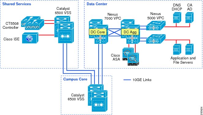
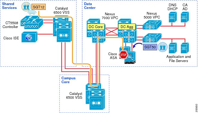
Figure 12-1 depicts the infrastructure that is used for purposes of SGA validation within the CVD.
Figure 12-1 TrustSec Infrastructure for BYOD v2.5 CVD
In Figure 12-1, the links extend between the Catalyst 6500 VSS in Shared Services to the Catalyst 6500 VSS in core and extends to the Nexus 7000 are 10GE links. On the Catalyst 6500s, WS-X6904 linecards with the FourX Adapters provide the 10GE interfaces while the N7K-M108X2-12L linecards provide the Nexus 7000 interfaces. The links between the Nexus 7000 and the Nexus 5548 are likewise connected to N7K-M108X2-12L linecards at the N7K and 10GE ports on the Nexus 5548. All other network connectivity for wireless controllers, ASA Firewalls, ISE, and the miscellaneous servers depicted are 1GE links.
Policy Configuration for SGACLs in Scenario 1
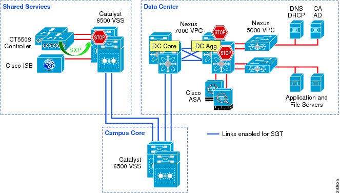
For Deployment Scenario 1, refer to Figure 12-2.
Figure 12-2 Infrastructure Deployment Scenario 1 SGT Enforcement
Deployment Scenario 1 requires that Security Group Tags are forwarded from the Shared Services Catalyst 6500 VSS, where the wireless controller is attached, through the core of the BYOD infrastructure enroute to servers located in the data center proper. In Figure 12-2, the links depicted in blue will be configured for SGT forwarding as well as manually configured for 802.1ae MACsec encryption. As previously discussed, the CT5508 wireless controller does not support native tagging on its 1GE interfaces, so a Security Group Tag Exchange Protocol (SXP) connection will be defined between the controller(s) and the Shared Services C6500 VSS switch as depicted above.
In this first scenario, wireless users, upon successful authentication and authorization, will be associated with a specific role and an IP to SGT mapping will be created on the wireless controller with the device's IP Address and the appropriate SGT. SXP will be used to communicate this mapping to the Shared Services Catalyst 6500s to which the wireless controllers are attached. As wireless user traffic egresses the Shared Services Catalyst 6500s, it will be tagged with the appropriate SGT learned via SXP from the wireless controller. As this traffic traverses the SGT-capable Core, this tag will be propagated hop-by-hop enroute to the Nexus 7000s comprising the data center switching infrastructure within which the various servers are located.
As 802.1X is not used to authenticate the servers residing in the Nexus data center infrastructure, the Server IP Address to SGT mapping can either be manually defined on the Nexus 7000 Data Center Aggregation switch or at the ISE server which would subsequently populate that mapping to the Nexus 7000. For purposes of the CVD, these mappings have been manually defined on the Nexus 7000 DC Aggregation Switch. As discussed in SGT Deployment Scenarios in this CVD in Chapter 5 "Campus and Branch Network Design for BYOD," there are other methods of associating traffic with a specific SGT on the Nexus 7000 platform.
As tagged user traffic arrives at the Nexus 7000 data center switch where the manual SGT mappings for the servers have been created, the traffic will be matched against TrustSec Policy (SGACL) defined either centrally at ISE or locally, as in the case of destination "Unknown" (SGT0), and will be either forwarded or dropped as applicable.
As discussed earlier, all server IP to SGT mappings have been manually created on the Nexus 7000 aggregation switches. As the servers are connected to the Nexus 5548 switches depicted in Figure 12-3, traffic from the Nexus 5548s egresses untagged as no mappings have been created there. Once this traffic passes through the Nexus 7000 Aggregation switch, the resident SGT mappings will be examined and the appropriate SGT imposed upon egress from the aggregation switch. In the event that traffic is initiated by a server associated with an SGT in the data center, the tagged traffic egresses the Nexus 7000 data center switches and traverses the Core and Shared Service infrastructure with the SGT propagated at each hop enroute to the destination, which is the wireless controller attached to the Shared Services 6500. Once the traffic arrives at the Shared Services 6500, the traffic will be matched against TrustSec Policy (SGACL) and will be either forwarded or dropped as defined.
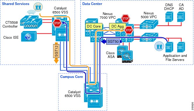
Figure 12-3 depicts where SGACLs will be enforced in the Unified Access infrastructure.
Figure 12-3 Policy Enforcement in Deployment Scenario 1
The following major tasks are required for this deployment scenario and are outlined in the following sub-sections in Chapter 23 "BYOD Policy Enforcement Using Security Group Access":
1.
Configuring ISE to Support TrustSec
2.
3.
a.
b.
c.
4.
5.
6.
a.
b.
7.
Policy Configuration in Scenario 2
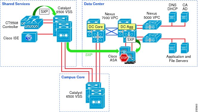
For the topology used in Deployment Scenario 2, refer to Figure 12-4.
Figure 12-4 Deployment Scenario 2 Configuration
With Deployment Scenario 2 an alternate means other than SGACLs is used to enforce SGA policy. In Scenario 2, the ASA running version 9.0 will be used as a Security Group Firewall (SG-FW) securing data center resources from outside access. As the ASA does not presently support Native SGT Tagging on its Ethernet interfaces, SXP must be used for it to learn IP/SGT mappings from other areas of the network where they have been dynamically learned or statically configured.
As in the case of the first deployment scenario, wireless users, upon successful authentication and authorization, will be associated with a specific role and an IP to SGT mapping will be created on the wireless controller with the device's IP Address and the appropriate SGT. Security Group Tag Exchange Protocol (SXP) will be used to communicate this mapping to the Shared Services Catalyst 6500s to which the wireless controllers are attached.
Unlike Scenario 1 however, the 10GE infrastructure between the Shared Services Catalyst 6500 VSS and the data center does not need to be enabled to support Security Group Tags or SGACLs. SXP will be used instead to re-advertise the mappings the Shared Services Catalyst 6500 VSS learned from the wireless controllers to the ASA Firewall.
The reason that a multi-hop SXP configuration is used from the wireless controller is primarily due to the fact that concentrating all of the controllers SXP advertisements at the 6500 VSS switch in Shared Services for single advertisement elsewhere in the network just provides a cleaner approach; it would be entirely possible to create the SXP peering directly between the wireless controller and the ASA firewall. The only other consideration lies in the fact that the WLC-5508 controllers used in this guide, as well as the WiSM2 only support four SXP connections, whereas the 6500 scales far beyond that.
In addition to the SXP Peering between the Shared Services 6500s and the ASA, the Nexus 7000 aggregation switches will require an SXP Peering to advertise SGT mappings that have been configured on them. It is by virtue of these SXP advertisements that the ASA is capable of inspecting the traffic from various devices and associating the appropriate tag for subsequent SG-FW policy enforcement as the ASA's interfaces are not TrustSec aware and incapable of manipulating the SGT.
As previously discussed, the ASA Firewall that will be used to enforce SG-FW policies must be manually configured with SGT policies as Network Device Admission Control (NDAC) is presently not supported in the ASA and is therefore unable to acquire these policies dynamically from ISE. For more information regarding NDAC, refer to Chapter 23 "BYOD Policy Enforcement Using Security Group Access." These policies as defined in Chapter 23 "BYOD Policy Enforcement Using Security Group Access" for Deployment Scenario 2 can be configured via CLI, ASDM, or a management platform such as Cisco Security Manager.
As wireless traffic egresses the Shared Services Catalyst 6500s en route to the data center, the traffic will be untagged and will simply pass through the Core, enter the data center switching infrastructure, and ultimately arrive at the ASA Firewall where the appropriate SG-FW policy will be enforced.
Should any traffic be sourced from a server in the data center, it will likewise egress the Nexus 7000 aggregation switch untagged and be forwarded to the ASA firewall where any applicable SG-FW policy will be enforced.
Figure 12-5 depicts the infrastructure used in Deployment Scenario 2 and the means by which security group policies will be enforced.
Figure 12-5 SGA Policy Enforcement Using SXP and SG-FW
The following major tasks are required for this deployment scenario and are outlined in the following sub-sections in Chapter 23 "BYOD Policy Enforcement Using Security Group Access":
1.
2.
3.
a.
b.
c.
4.
a.
b.
c.
5.
6.
TrustSec Summary
For information regarding the detailed, platform-specific configuration steps, refer to the TrustSec section in Chapter 23 "BYOD Policy Enforcement Using Security Group Access."
Note