-
Cisco Bring Your Own Device (BYOD) CVD Release 2.5
- Introduction
- Design Overview
- Configuring the Infrastructure
- BYOD Use Cases
-
Operations and Services
-
Summary of Operations and Services
-
BYOD Guest Wireless Access
-
Managing a Lost or Stolen Device
-
BYOD Policy Enforcement Using Security Group Access
-
Mobile Traffic Engineering with Application Visibility and Control (AVC)
-
Managing Bonjour Services for BYOD
-
BYOD Remote Device Access
-
BYOD Network Management
-
- Appendices
Table Of Contents
BYOD Policy Enforcement Using Security Group Access
ACL Complexity and Considerations
Security Group Access Domain Infrastructure
TrustSec using 802.1X for Link Encryption
TrustSec in Manual Mode for Link Encryption
Security Group Tag Distribution and Forwarding Mechanisms
SGT Assignment for Data Center Servers
SGT Deployment Scenarios in this CVD
Configuring the Infrastructure for TrustSec
Unified Infrastructure Design to Support TrustSec
TrustSec Policy Configuration for SGACLs in Infrastructure Deployment Scenario 1
Configuring ISE to Support TrustSec
Configuring ISE for Network Access Device Authentication
Configuring Network Devices with a Device SGT
Configuring Network Access Devices for Authentication at ISE
RADIUS Server Configuration on the Wireless Controller
Enabling TrustSec on the Catalyst 6500
RADIUS Server Configuration on the Catalyst 6500
Enabling TrustSec on the Nexus 7000
RADIUS Server Configuration on the Nexus 7000
Catalyst 6500 Platform Specific Considerations
Configuring Switching Infrastructure to Support TrustSec with 802.1ae MACsec Encryption
Configuring Security Group Tag Exchange Protocol (SXP) for Wireless Controllers
Wireless Controller Configuration
Catalyst 6500 SXP Configuration
Configuring Static IP/SGT Bindings on Nexus Switches
Configuring ISE to Support TrustSec
Configuring ISE for Network Access Device Authentication
Wireless Controller Configuration
Configuring the Network Devices for Integration with ISE
RADIUS Server Configuration on the Wireless Controller
RADIUS Server Configuration on the ASA Firewall
RADIUS Server Configuration on the Nexus 7000
Configuring Security Group Tag Exchange Protocol (SXP) for Wireless Controllers
Wireless Controller Configuration
Catalyst 6500 SXP Configuration
Configuring Static IP/SGT Bindings on Nexus Switches
Configuring SG-FW Role-Based Policies at ASA
Device On-boarding, Provisioning, Authentication, and Authorization Policies for TrustSec in ISE
BYOD Policy Enforcement Using Security Group Access
Revised: November 25, 2013Security Group Tag Overview
The BYOD CVD has primarily relied on Access Controls Lists for policy enforcement to restrict user traffic as appropriate upon successful authentication and authorization. The use of ACLs can become a daunting administrative burden when factoring the number of devices upon which they are applied and the continual maintenance required to securely control network access.
This CVD uses a complimentary technology known as TrustSec and the use of Security Group Tags (SGT). Security Group Tags offer a streamlined and alternative approach to enforcing policy and traffic restrictions with minimal and in some cases, little or no ACLs at all if TCP/UDP port level granularity is not required.
Security Group Tags will be used as an alternative to ACLs for enforcing role-based policies for campus wireless devices where the Cisco Wireless Controllers have been centrally deployed and configured for operation in local mode (wireless traffic locally switched at the controller).
ACL Complexity and Considerations
To date, variations of named ACLs on wireless controllers, static and downloadable ACLs on various routing and switching platforms, as well as FlexACLs for FlexConnect wireless traffic in the branch have been used as a means of enforcing traffic restrictions and policies. In order to configure and deploy these ACLs, a combination of either command line (CLI) access to each device via Telnet/SSH or network management such as Prime Infrastructure have been required and used for statically configured ACLS while the Cisco Identity Services Engine (ISE) has been used to centrally define and push downloadable ACLs (DACL) to switching platforms.
•
Unique ACLs may be required for different locations such as branches or regional facilities, where user permissions may need to be enforced for local resources such as printers, servers, etc.
•
•
•
•
Cisco's TrustSec provides a scalable and centralized model for policy enforcement by implementing Cisco's Security Group Access architecture and the use of Security Group Tags.
Security Group Tag
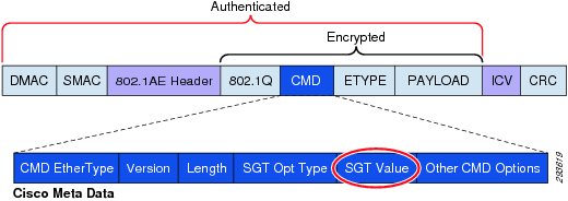
Security Group Tags, or SGT as they are known, allow for the abstraction of a host's IP Address through the arbitrary assignment to a Closed User Group, represented by an arbitrarily defined SGT. These tags are centrally created, managed, and administered by the ISE. The Security Group Tag is a 16-bit value that is transmitted in the Cisco Meta Data field of a Layer 2 Frame as depicted in Figure 23-1.
Figure 23-1 Layer 2 SGT Frame Format
The Security Group Tags are defined by an administrator at Cisco ISE and are represented by a user-defined name and a decimal value between 1 and 65,535 where 0 is reserved for "Unknown". Security Group Tags allow an organization to create policies based on a user's or device's role in the network providing a layer of abstraction in security policies based on a Security Group Tag as opposed to IP Addresses in ACLs.
The SGT is dynamically assigned, or bound, to user/device's IP Address upon successful AAA Authentication and subsequent Authorization to the network via Cisco ISE. This SGT mapping is communicated to and stored at the Network Access Device (NAD) serving as the Authenticator. On Cisco switches, these mappings may be dynamically created through RADIUS Attribute Value (AV) pairs passed down from ISE; or may optionally be defined at the device for a host's IP Address, physical port, VLAN, or subnet, depending on the switching platform's capabilities. In the case of Cisco Unified Wireless Network (CUWN) wireless LAN controllers such as the WiSM2 or CT5508 however, these IP to SGT mappings can only be dynamically created at the controller through the information communicated by ISE. For specific platform capabilities, refer to the appropriate configuration guides found at http://www.cisco.com or in the Cisco TrustSec Switch Configuration Guide at: http://www.cisco.com/en/US/docs/switches/lan/trustsec/configuration/guide/sgacl_config.html#wp1054201.
For additional information regarding the Security Group Access architecture, refer to the TrustSec Design and Implementation Guide at: http://www.cisco.com/en/US/solutions/ns340/ns414/ns742/ns744/landing_DesignZone_TrustSec.html.
Security Group Access Domain Infrastructure
There are two methods of configuring the infrastructure to support TrustSec enabling the forwarding and policy enforcement of frames with an embedded Security Group Tag.
•
•
Common to both of these methods is first the ability to employ MACsec (802.1ae) which provides encryption, a message integrity check, and data-path replay protection for links between adjacent network devices thereby protecting the CMD field and the SGT value it contains. Second is configuration for 802.1X authentication between those network devices that will enforce policies based on the SGT and the Cisco Identity Services Engine (ISE) acting as an Authentication Server.
TrustSec using 802.1X for Link Encryption
The first method for configuring an TrustSec infrastructure makes use of 802.1X to establish a domain of authenticated and trusted network devices. Every networking device in the TrustSec Domain must be authenticated either directly with ISE, or through its neighbor acting as an authenticator on behalf of the Supplicant network device.
The first networking device to join a TrustSec Domain is considered to be the "Seed" Device. When first powered on, it acts as an 802.1X supplicant joining the TrustSec Domain through an EAP-FAST exchange with ISE as the Authentication Server. Upon successful authentication with ISE, the network device will, through the EAP provisioning tunnel, receive a Protected Access Credential (PAC) key and secure token generated by ISE. This key is used for all future RADIUS Exchanges with ISE.
Seed devices are configured with the list of ISE servers against which it can authenticate. It is not necessary to provide this list of AAA servers on every device when 802.1X is used and subsequently, as adjacent networking devices configured for TrustSec come up, the seed device will act as an 802.1X Authenticator to its neighbor as a Supplicant. As such these neighbors are considered to be "non-seed" devices. This process is known as Network Device Admission Control or NDAC. Once the networking devices have authenticated against ISE, a common Pairwise Master Key (PMK) is derived for use by both sides during subsequent mutual authentication and MACsec negotiation with optional encryption for each of the interconnecting interfaces.
Finally each device, using the credentials acquired after successful authentication with ISE, will through Secure RADIUS exchange, acquire SGT definitions and policies to be enforced in the network.
For additional information regarding NDAC and MACsec, please refer to the Cisco TrustSec 3.0 document "Introduction to MACSec and NDAC" which can be found in Design Zone on Cisco.com at: http://www.cisco.com/en/US/solutions/ns340/ns414/ns742/ns744/landing_DesignZone_TrustSec.html.
TrustSec in Manual Mode for Link Encryption
The second method, depicted in this CVD, does not rely on 802.1X for device link authentication and encryption. To enable link protection without 802.1X, TrustSec manual mode can be configured such that a common Pairwise Master Key (PMK) is manually configured on the respective interfaces for use by both sides during subsequent MACsec negotiation and optional encryption. This is one of the primary differences with TrustSec with 802.1X wherein this key is dynamically derived from the credentials acquired from ISE after successful authentication.
Another distinction between 802.1X mode and manual mode lies in how the concept of a TrustSec domain of trust is established. When using 802.1X for link authentication, the network device credentials are used during the process of bringing the link up and subsequent authentication with the peer interface; this establishing a trust state with the adjacent device. As this 802.1X-based mechanism is unavailable when configuring manual mode, a static policy must be defined establishing a trusted state on both side of a TrustSec enabled link in addition to the manual PMK configuration.
As in the case of TrustSec with 802.1X link authentication, communication on the links between trusted devices in the TrustSec domain can be secured with a combination of encryption, message integrity checks, and data-path replay protection mechanisms through the use of 802.1ae MACsec. This encryption capability allows the SGT value carried in the Cisco Meta Data (CMD) field of the 802.1q Header to be protected. Today, there are two keying mechanisms available for use with 802.1ae based encryption, the first is a Cisco proprietary protocol known as Security Association Protocol or SAP (similar to 802.1X-2010 MKA) and the second, a standards-based mechanism known as MACsec Key Agreement or MKA. Both use Galois Message Authentication Code (GMAC) as a mechanism to provide authentication and 128-bit AES-GCM (Galois/Counter Mode) symmetric encryption, which is capable of line-rate encryption and decryption for both 1 GB and 10 GB Ethernet interfaces, and provides replay attack protection of every frame. Within this CVD, SAP is used as the keying mechanism for all 10GE MACsec links.
SAP, is a key derivation and exchange protocol based on a draft of IEEE 802.11i which performs the following functions:
•
•
•
•
•
SAP supports the following modes:
•
•
•
•
When configuring the TrustSec infrastructure to make use of Manual Mode on the links as opposed to 802.1X mode, there is no requirement to configure every network device to support 802.1X-based link authentication. However, the requirement for 802.1X configuration and network device authentication at ISE still exists for those devices that will require SGT definitions and mappings as well as for SGT-based policy enforcement.
In order to authenticate, the network device(s) will require a configuration identifying the AAA servers (ISE) against which they will authenticate. Once a device has successfully authenticated, secure RADIUS using a PAC key and secure token acquired during authentication is used to communicate with ISE to acquire TrustSec environmental data such as the Security Group Name and the numeric value associated with the tag, an optional SGT used by the device to source packets, and SGT/IP mappings that have been created at ISE. Additionally, policies based on SGTs in the form of SGACLs created at ISE are pushed out to those devices capable of enforcing them such as certain Catalyst and Nexus switching platforms.
Note
In the BYOD v2.5 CVD, this 802.1X configuration for network device authentication will be configured at only two locations in the infrastructure to be discussed later; a Shared Services block where the wireless controllers have been deployed and at the data center aggregation switches. As discussed later, these will be the two locations in the network where policies based on SGTs will be enforced using dynamically acquired SGACLs. Although it is entirely possible to configure every device in the path for 802.1X authentication it is purely optional as SGACLs are enforced upon egress from the device having a corresponding destination IP Host to SGT mapping matching an SGACL. The devices that are in the path between source and destination will not have this mapping typically and hence this TrustSec environment data will not be applicable or enforceable.
Security Group Tag Distribution and Forwarding Mechanisms
In order to impose or forward a frame with an SGT Value, specialized switching ASICs are required for forwarding on Ethernet Ports. A variety of Cisco switching platforms in the Nexus and Catalyst families support the inline tagging of an SGT value on 10G Ethernet Ports and to a lesser extent, 1G Ethernet depending on the platform. This SGT inline tagging capability is sometimes referred to as SGToverEthernet or "native tagging". In the BYOD v2.5 CVD the Catalyst 6500 with SUP2T and WS-X6904 linecards as well as the Nexus 7000 with SUP1 and M1 linecards will provide the 10GE connectivity supporting SGT imposition and forwarding in the Services, Core, and data center in the campus network. For specific information regarding platform support for SGT inline tagging, refer to the appropriate product documentation at
http://www.cisco.com or the "TrustSec Switching Configuration Guide" at: http://www.cisco.com/en/US/docs/switches/lan/trustsec/configuration/guide/trustsec.html.
For the network access devices (NAD) capable of SGT native tagging, when a user or device is authenticated and a SGT Value has been forwarded as a RADIUS AV to the NAD, this IP to SGT mapping will be created and stored at the access switch. Frames sourced from that user or device will be tagged upon egress from the switch on a physical port or, in the case of an SVI, internally associated with the packet as it egresses the SVI. In either case, if an SGACL is matched prior to egress from the device or SVI, the action defined in the SGACL will be enforced otherwise the packet with the imposed SGT will be forwarded.
Note
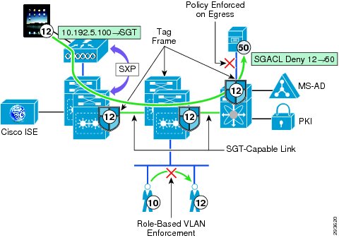
In certain Catalyst and Nexus switching products, it is also possible to enable role-based enforcement within a VLAN, where an SGACL may be enforced between devices with different SGT values. Refer to Figure 23-2.
Figure 23-2 SXP Advertisement, SGT Imposition, and SGACL Enforcement
Packets that have a Security Group Tag applied can be forwarded throughout an infrastructure as long as those network devices support SGToverEthernet or native tagging and the link has been configured with the appropriate policy defining whether those tags should be trusted or re-written through the use of the <policy static> command on the TrustSec interface. As a packet arrives at a switch that supports SGToverEthernet for example, the switch will remove and inspect the header to perform forwarding lookups, apply any QOS treatment, and act upon any security ACLs configured there. Providing the intermediate device does not have an IP to SGT mapping that is denied in an SGACL at this device, the packet will be forwarded along with the associated SGT towards the destination where an egress SGACL will be enforced (permit or deny).
For those platforms that do not support the native SGT tagging capabilities, the SGT eXchange Protocol or SXP as it is known was created to advertise IP Address to SGT Binding information. On devices that support SXP only, they are considered to be "SGT-Aware", the 802.1X authentication and authorization of a user is exactly the same as those devices supporting native tagging. On these devices supporting SXP, the IP to SGT mapping is created and maintained and can be advertised to a device where native tagging is supported. This advertisement or SXP "Peering" as it is known can be created to an adjacent device or one that is multiple L2 or L3 hops away as SXP uses TCP as a communications transport between peered devices. Refer to Figure 23-2.
As untagged packets sourced from a device advertising IP to SGT mappings via SXP arrive at a switch that is capable of native tagging, the source IP Address is identified and either the associated SGT can be added to the packet and forwarded or an applicable SGACL enforced.
For a detailed explanation of SXP and SGT, see the TrustSec Design and Implementation Guide at: http://www.cisco.com/en/US/solutions/ns340/ns414/ns742/ns744/landing_DesignZone_TrustSec.html.
User Policies with SGT
When a user/device accesses the network for the first time, whether wired or wireless, as described in the CVD the network access device (NAD), wireless controller or switch, serves as an 802.1X authenticator to start the authentication process. The AAA server against which the user will be authenticated will be the Cisco Identity Services Engine (ISE). As this is the first time the device has been seen on the network, it will first be provisioned with the proper credentials for access to the network. During this provisioning process, access to the network will be restricted though the use of standard ACLs to those services such as DHCP, DNS, ISE, and the Google PlayStore required for on-boarding the device as specifically defined in the BYOD CVD.
Once a device has been successfully on-boarded and provisioned, the network access device (NAD) once again acts as an 802.1X authenticator to start the device/user authentication process with ISE. During this authentication process, the device/user is identified based on credentials offered such as a Digital Certificate or Active Directory Group membership. In past versions of the BYOD CVD, once authenticated, users or devices would have been authorized and based on a matching policy would have either been granted unrestricted access to the network or perhaps partial access, restrictions enforced by a suitable ACL either downloaded in the case of switches or associated with a statically configured (named) ACL on the networking device. As an alternative to this approach, an SGT can be used and upon identifying the appropriate authorization policy in ISE, the NAD will receive and store the appropriate SGT to be associated with the user or device's IP Address, commonly referred to as an IP to SGT Binding.
Based on these Security Group Tags, role-based policies can be enforced on supporting hardware through the use of Security Group ACLs (SGACLs) on Cisco switching infrastructure, policies defined on Security Group Firewalls (SGFW) such as the ASA, or an SGFW implemented on the IOS Zone-Based Firewall (ZBFW) on Cisco Routers. These policies may be as simple as a permit or deny an SGT statement or may include specific IP Port information in addition to source or destination SGT to identify specific applications or traffic.
It should be apparent, that when an abstraction layer such as the TrustSec architecture and SGTs are used, device and virtualized server mobility is greatly enhanced as the IP Address of the device is no longer a consideration in enforcing policies in the network. This is true as long as the SGT value was dynamically assigned through a port profile when using the Nexus 1000V, by ISE based on authorization policy, or if the mapping was the result of a VLAN, L3 interface, or IP Subnet to SGT Binding with the VLAN, L3 interface, or Subnet duplicated on other devices. Now, as an entity moves in the network either through mobile roaming or server vMotion by virtue of the port profile when using the Nexus 1000V, one need not be concerned with having appropriate address-based ACLs defined on the destination device. The policy can follow them based on the SGT they have been assigned. If however the IP Host Address to SGT mapping were statically defined at a networking device, that mapping is only resident on that device and not shared with other devices in the TrustSec Domain.
Through the use of Security Group Tags, it will be possible to eliminate many of the Downloadable and named ACLs required in previous BYOD CVDs with a ubiquitous set of tags applicable to an entire domain and managed centrally at the ISE.
This CVD uses TrustSec as an alternative to named ACLs for campus wireless (centralized) access. As of Cisco Unified Wireless Networking (CUWN) software release 7.4MR1 and 7.5 for the WiSM2 and CT5508, sixty-four ACLs can be configured, each having sixty-four Access Control Entries or ACEs (permit/deny statements) within an ACL. In most organizations this may not be an issue, however in others, this may be too limited when using ACLs to segment the network based on roles or device types or if the devices are a Corporate or Personal asset. When using ACLs, a Named ACL is created on the wireless controller and as a user is authenticated and authorized, ISE pushes down the name of the ACL to be applied to the user in the RADIUS AV pair returned to the controller. If there are more than sixty-four unique roles, or more likely more than sixty-four Access Control Entries in an ACL, the use of named ACLs will not be possible. For these scenarios, TrustSec offers an extremely scalable alternative where hundreds of roles may be identified for users or devices, thereby eliminating the requirement for the use of specific IP addresses in an ACL.
The policies demonstrated in this CVD cover the use case where North/South (wireless access to data center) policies need to be enforced restricting access to resources in the data center. Although entirely possible, East/West (wireless user to user) policy enforcement using SGT will be considered out of scope for this version of the CVD. East/West traffic enforcement will be included in a future version of the BYOD CVD when wired access with SGT is addressed.
SGT Assignment for Data Center Servers
Unlike campus access through Catalyst Switches and Cisco Wireless Controllers where dynamic SGT mappings are communicated and created through 802.1X and RADIUS exchange, the vast majority of organizations do not implement 802.1X for server connectivity. As such, data center switches such as the Cisco Nexus switches provide only limited support for the use of 802.1X and do not specifically support an SGT RADIUS AV as an option. Although 802.1X support would be available if using Catalyst Switches in the data center, this use case is not covered. Therefore, IP Address to SGT mappings for these resources must be either manually defined as in the case of bare metal servers and non-Cisco virtual switches or within port profiles if the Cisco Nexus 1000V virtual switch is deployed.
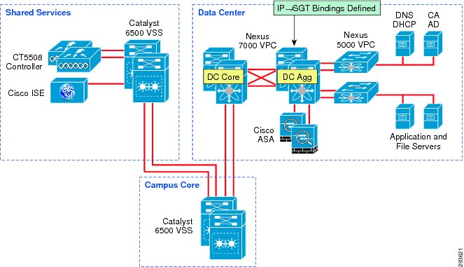
For purposes of this CVD we have defined our IP to SGT Bindings at a Nexus 7000 data center aggregation layer switch as depicted in Figure 23-3.
Figure 23-3 Server IP to SGT Bindings
In addition to the manual creation of an IP Address to SGT mapping either globally, or within a VLAN for enforcement of intra-vlan traffic between hosts belonging to different Security Groups, the Nexus 7000 also supports the following:
•
•
The Nexus 5500 as of this version of the CVD, only supports the manual IP to SGT mapping Globally or within a VLAN as previously described for the Nexus 7000.
For the Nexus 1000V, the SGT can be assigned within the port profile definition and subsequently advertised via SXP to a device such as the Nexus 7000 or 5500 for SGT imposition or SGACL enforcement. The use of the Nexus 1000V is considered out of scope for this release of the BYOD CVD, however additional information can be found in "Segmenting Clients and Servers in the Data Center" at: http://www.cisco.com/en/US/solutions/ns340/ns414/ns742/ns744/landing_DesignZone_TrustSec.html.
Finally, it is also possible to define these SGT host mappings within ISE. These mappings are subsequently pushed to all SGT-capable network devices authenticated within the TrustSec Domain. An SGT-capable device can impose and forward the SGT as well as enforce an SGACL. The exceptions here are the ASA, as its Security Group policies are not dynamically obtained but locally configured, and devices that are only SGT-Aware (only SXP supported). Although an effective means of dynamically deploying these mappings throughout the network, it may be impractical from a scaling perspective as every device would possess every server mapping within the TrustSec Domain. Although possible to access each networking device and remove the mapping manually within the configuration this may prove to be very operationally intensive. Within the BYOD CVD we advocate a locally defined configuration in the Aggregation switches closest to the server and once available on the Nexus 7000, recommend the use of VLAN to SGT mapping; note that VLAN to SGT mapping is currently unavailable for the Nexus 5500.
As the implementation of TrustSec within the data center will most likely be through a migrational approach, we advocate that those resources or servers that all users have access to be some of the first identified for policy enforcement through the use of SGT and assignment to a security group. In doing so, as users or devices are associated with an SGT representing a role that has access to only these devices and nothing else, a policy can be created granting that specific access while denying everything else based on the use of SGT 0 or the "Unknown" tag.
A key concept to be considered when granting access to the data center is that of the SGT value of zero or "Unknown" as it is referred to. If the IP Address of a server has not been mapped to an SGT at the point of enforcement such as the Nexus 7000 in the data center, that server would be considered Unknown and associated with SGT 0. Unlike ACLs with an implicit deny at the end, SGACLs when implemented on a switching platform have an implicit permit to Unknown or all; this is not true on the ASA or IOS ZBFW acting as a SG-FW where an implicit deny is still maintained. Hence on a switch, if there is not a specific tag value assigned to a server, the destination is considered Unknown (SGT 0) and the packet forwarded. This SGT 0 thus allows a migrational approach to tag assignment in the data center.
In a BYOD setting where personal or contractor assets are permitted on the network and only partial access to data center resources is permitted through the use of SGACLs on the switching infrastructure, the task of assigning an SGT to every data center asset will likely prove daunting when first migrating to the use of Security Group Tags as it is not possible to create a switch-based SGACL using both SGT and IP addresses; the destination SGT of the device must be known. Hence it is with this in mind that the concept of the Unknown tag may be used to provide a phased approach to SGT assignment. Throughout the campus infrastructure the default policy permitting any SGT to "Unknown" is left unaltered. However, at the Nexus 7000 Data Center Aggregation switches where policies based on SGACLs are enforced, an explicit deny of a given source SGT to "Unknown" can be created. A policy that is explicitly (manually) configured at a networking device will take precedence over a policy that is dynamically received from ISE.
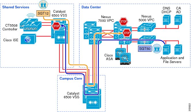
In the BYOD CVD the approach followed is to group users and devices with only partial access to the data center and assign them to SGT12 for example. Within the data center, we group those resources that SGT12 will have access to together using an SGT value 40. Servers that these users should not be able to access and that have already been associated with as SGT are assigned SGT 50. In doing so we enforce three policies regarding server access:
•
•
•
For users or devices that have full access to data center resources and are assigned a different SGT, the default, implicit permit to Unknown is left in place and any other SGT-based restrictions can be enforced as required. An example might be in the case of a web server and its corresponding database where a corporate device can access the web server but only the web server and DB Admins can access the database.
When using an ASA firewall to protect data center resources additional flexibility in policy definition is possible as either a source or destination SGT can be used with a destination or source IP Address in the ACE. This now allows one to create policies where a tag assigned to users/devices with partial access can be granted or denied to specific SGTs and or IP Addresses. When using an SG-FW to enforce policy, an ACE can be defined denying a source SGT access to "Unknown" as well.
Prior to implementation of a Security Group Access architecture, many organizations may have already designed their data centers in such a way as to protect those resources by placing them behind a firewall. Others may simply elect to secure them through the use of access control lists where only specific access has been granted while general access from all other sources is denied. Both approaches are demonstrated within this CVD, where campus Wireless BYOD users and devices have role-based access through the use of Security Group Access Control Lists (SGACLs) and the Security Group Firewall (SG-FW) capability found in the ASA. It should be pointed out that these two approaches, SGACLs and SG-FW, are not mutually exclusive and may be used together.
It is beyond the scope of this CVD to provide a detailed approach to developing a migration strategy for the implementation of Security Group Tags in the data center as well as providing architectural guidance for secure, containerized, data centers. For additional information on these topics, refer to the data center document repository in Design Zone on Cisco.com at: http://www.cisco.com/en/US/netsol/ns743/networking_solutions_program_home.html as well as the TrustSec document repository at: http://www.cisco.com/en/US/solutions/ns340/ns414/ns742/ns744/landing_DesignZone_TrustSec.html.
SGT Deployment Scenarios in this CVD
The BYOD CVD addresses four different Use Cases based on the type of network access that an organization will permit.
•
•
•
•
Specifically, SGT will be used as a means of policy enforcement for the Enhanced Access Use Case where a campus wireless user/device terminated centrally at a wireless controller in Local Mode is granted either full or partial access to the network. Different classes of servers will be defined to which those users may or may not have access to. The CVD also defines a class that has access to the Internet only. For BYOD v2.5, an ACL on the wireless controller is used to deny access to all but the Internet. The Converged Access products such as the Catalyst 3850 and CT-5760 will not be addressed relative to SGT in this CVD as Security Group Tags and SXP are currently not supported. More about SGT and the Enhanced Use Case will be discussed in the ensuing section discussing the actual authorization policies.
Two deployment scenarios will be depicted within this CVD, the first will make use of SGACLs to enforce policies at the Nexus 7000 data center switches, whereas the second scenario will enforce policies configured at a Cisco ASA configured as a Security Group Firewall (SG-FW). Again, these deployment scenarios are not mutually exclusive and can be used together. This first scenario can be seen in Figure 23-4 and the second scenario follows in Figure 23-5.
Figure 23-4 Policy Enforcement using SGACL
Figure 23-5 Policy Enforcement using SG-FW
Configuring the Infrastructure for TrustSec
The following section describes the infrastructure to be used in this CVD and provides an outline of the two deployment scenarios to be used to enforce policies based on Security Group Tags. These deployment scenarios are not mutually exclusive and may be used together to satisfy an organization's requirements. Configuration details for the infrastructure are provided.
Unified Infrastructure Design to Support TrustSec
As described previously in the Design Overview section, two specific infrastructure deployment scenarios will be examined within this CVD. The first use case will make use of TrustSec Policy defined at the Identity Services Engine and the resulting SGACLs being dynamically exchanged with the Catalyst 6500 and Nexus 7000 infrastructure. The second use case will once again make use of the TrustSec Policy defined at the Identity Services Engine but will enforce this policy through the configuration of Security Group Firewall (SG-FW) policies defined on an ASA providing secure access to data center resources.
In both scenarios, campus wireless users/devices connecting through the centralized CUWN CT5508 controllers configured for local mode, will have access to data center resources based on their authorized roles and enforced through the use of SGT-based policies as implemented in the two deployment scenarios.
The infrastructure components that will be used for the policy enforcement through the use of Security Group Tags in the CVD consist of the following Cisco products.
Wireless Deployment Scenario 1 Components:
•
•
•
•
•
•
•
•
•
Wireless Deployment Scenario 2 Components:
•
•
•
•
•
•
•
•
•
•
Note
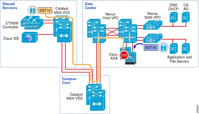
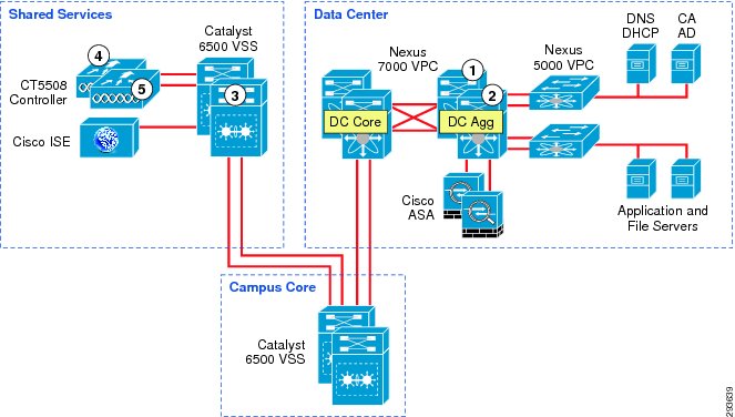
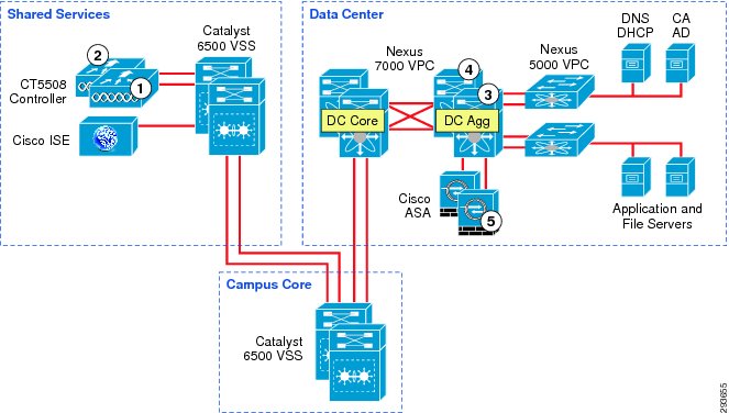
Figure 23-6 depicts the infrastructure that is used for purposes of TrustSec validation within this CVD.
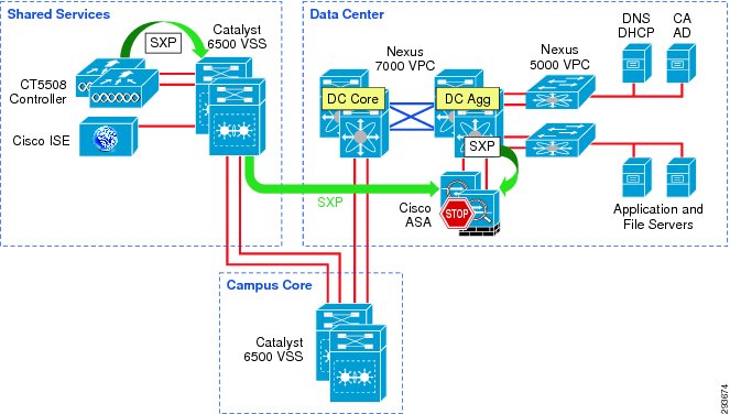
Figure 23-6 TrustSec Infrastructure This BYOD CVD
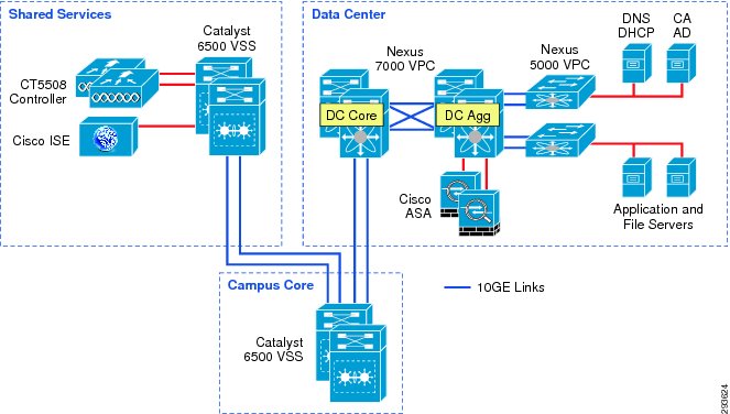
In Figure 23-6 the links extending between the Catalyst 6500 VSS in Shared Services to the Catalyst 6500 VSS in the core and extending to the Nexus 7000 are 10GE links. On the Catalyst 6500s, WS-X6904 linecards with the FourX Adapters provide the 10GE interfaces while the N7K-M108X2-12L linecards provide the Nexus 7000 interfaces. The links between the Nexus 7000 and the Nexus 5548 are likewise connected to N7K-M108X2-12L linecards at the Nexus 7000 and 10GE ports on the Nexus 5548. All other network connectivity for wireless controllers, ASA firewalls, ISE, and the miscellaneous servers depicted are 1GE links.
TrustSec Policy Configuration for SGACLs in Infrastructure Deployment Scenario 1
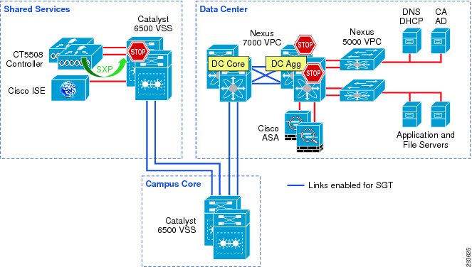
For Deployment Scenario 1, refer to Figure 23-7.
Figure 23-7 Infrastructure Deployment Scenario 1 SGT Enforcement
Deployment Scenario 1 will require Security Group Tags be forwarded from the Shared Services Catalyst 6500 VSS, where the wireless controller is attached, through the Core of the BYOD infrastructure en route to servers located in the data center proper. In Figure 23-7 above, the links depicted in blue will be configured for SGT forwarding as well as manually configured for 802.1ae MACsec encryption. As previously discussed, the CT5508 wireless controller does not support native tagging on its 1GE interfaces, as such a Security Group Tag Exchange Protocol (SXP) connection will be defined between the controller(s) and the Shared Services Catalyst VSS switch as depicted above.
In this first scenario, wireless users, upon successful authentication and authorization will be associated with a specific role and an IP to SGT Binding will be created on the wireless controller with the device's IP Address and the appropriate SGT. SXP will be used to communicate this mapping to the Shared Services Catalyst 6500s to which the wireless controllers are attached. As wireless user traffic egresses the Shared Services Catalyst 6500s, it will be tagged with the appropriate SGT learned via SXP from the wireless controller. As this traffic traverses the SGT-capable Core, this tag will be propagated hop-by-hop en route to the Nexus 7000s comprising the data center switching infrastructure within which the various servers are located.
As 802.1X is not used to authenticate the servers residing in the Nexus data center infrastructure, the server IP Address to SGT Binding can either be manually defined on the Nexus 7000 Data Center Aggregation switch or at the ISE server which would subsequently populate that mapping to the Nexus 7000. For purposes of the CVD, these mappings have been manually defined on the Nexus 7000 data center Aggregation Switch. As discussed in the design overview, there are other methods of associating traffic with a specific SGT on the Nexus 7000 platform.
As tagged user traffic arrives at the Nexus 7000 data center switch where the manual SGT mappings for the servers have been created, the traffic will be matched against TrustSec Policy (SGACL) defined either centrally at ISE or locally, as in the case of destination "Unknown" (SGT0), and will be either forwarded or dropped as applicable.
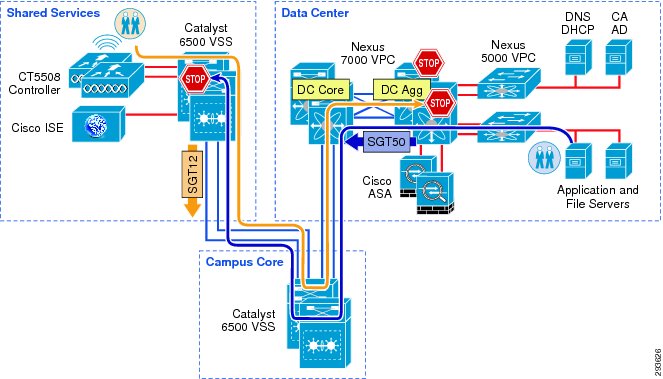
As discussed earlier, all server IP to SGT mappings have been manually created on the Nexus 7000 aggregation switches. As the servers are connected to the Nexus 5548 switches depicted in Figure 23-8, traffic from the Nexus 5548s egresses untagged as no mappings have been created there. Once this traffic passes through the Nexus 7000 Aggregation switch, the resident SGT mappings will be examined and the appropriate SGT imposed upon egress from the aggregation switch. In the event that traffic would be initiated by a server associated with an SGT in the data center, the tagged traffic would then leave the Nexus 7000 data center switches traversing the Catalyst 6500 Core and Shared Service infrastructure with the SGT propagated at each hop towards the destination; the wireless controller attached to the Shared Services 6500. Once the traffic arrives at the Shared Services 6500, the traffic will be matched against TrustSec Policy (SGACL) and will be either forwarded or dropped as defined.
Figure 23-8 depicts where SGACLs will be enforced in the Unified Access infrastructure.
Figure 23-8 Policy Enforcement in Deployment Scenario 1
The following major tasks are required for this deployment scenario and outlined in the following sub-sections:
1.
2.
3.
a.
b.
c.
4.
5.
a.
b.
6.
a.
b.
7.
Configuring ISE to Support TrustSec
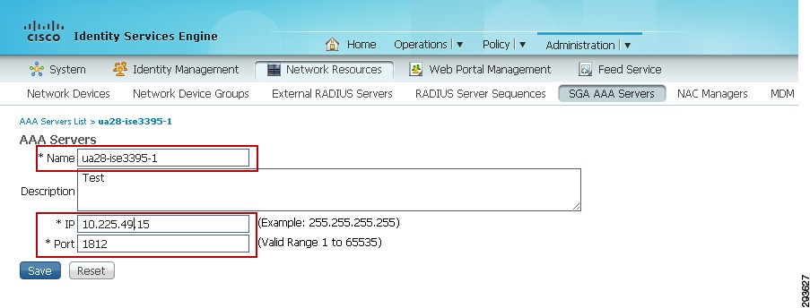
For Cisco ISE to function as a TrustSec server and provide TrustSec services, you must define the following global TrustSec settings. The first step is to define ISE as an TrustSec AAA server as depicted in Figure 23-9.
1.
2.
3.
4.
Figure 23-9 ISE TrustSec Server AAA Definition
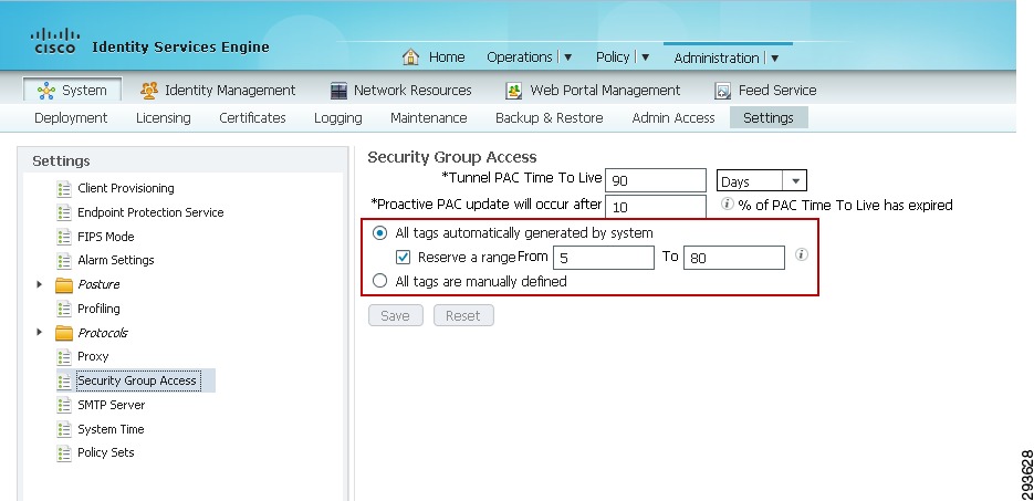
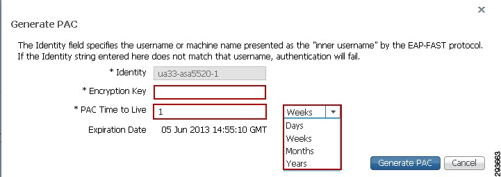
The next step to be completed is to configure TrustSec Server Protected Access Credential (PAC) Time-to-Live settings and SGT reservations.
The tunnel PAC generates a tunnel for the EAP-FAST protocol and is used for Secure RADIUS communications with Network Devices for TrustSec environmental data. A new PAC is generated if the network device re-authenticates for any reason or when the TTL expires.
By default Security Group Tags are dynamically assigned a decimal/hex value in ascending order by ISE. It is possible to change this behavior such that all tags must be manually defined or to reserve a range that can be specifically allocated to users, devices, or servers. In the CVD, a range of SGT values is reserved for allocation among users/devices and servers. Figure 23-10 depicts the reservation of Tags 5 through 80 for use in the CVD.
To complete this step:
1.
2.
3.
4.
5.
Figure 23-10 TrustSec Servers Settings in ISE
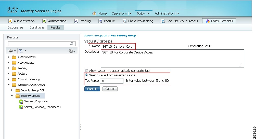
The next step is to define Security Group Tag names and associate them with a numerical value at the Identity Services Engine. The SGT names are periodically pushed to the Network Access Device (NAD) through periodic updates or upon that network device's authentication (NDAC Authentication) with ISE. They may also be manually pushed as well.
To complete this step as depicted in Figure 23-11:
1.
2.
3.
4.
5.
Figure 23-11 Security Group Creation
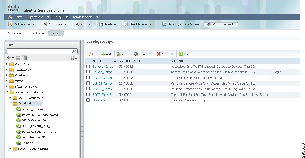
In this CVD, Table 23-1 shows the SGT Names and corresponding Tag Values used.
These values will be defined in ISE as can be seen in Figure 23-12.
Figure 23-12 Security Groups Used in CVD
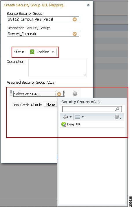
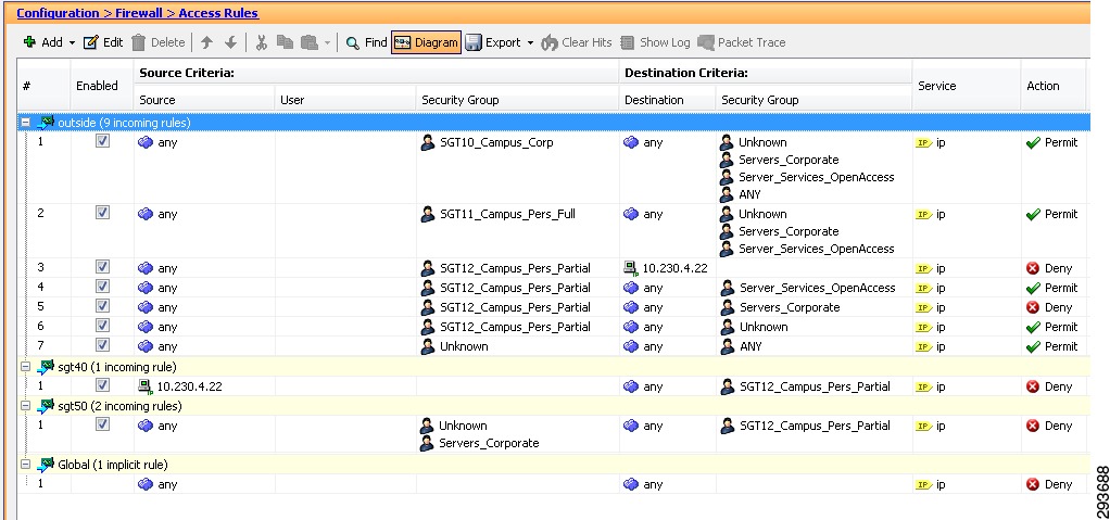
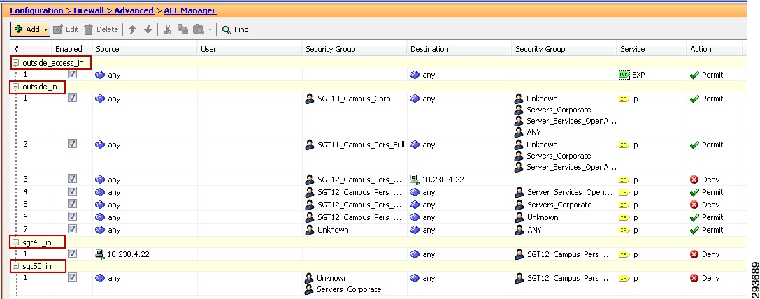
The next step for TrustSec configuration at ISE will be the definition of the actual policy to be enforced. As discussed previously, the TrustSec Policy will only be created for use as an SGACL on Catalyst and Nexus switching products. The ASA family of firewalls as of v9.0 do not support dynamic creation/update of the policies defined in ISE. Only the actual Security Group Names and Tag value are dynamically acquired from ISE. The policy used in this CVD is depicted in Figure 23-13.
Figure 23-13 TrustSec Policy to be Enforced
Note
Note
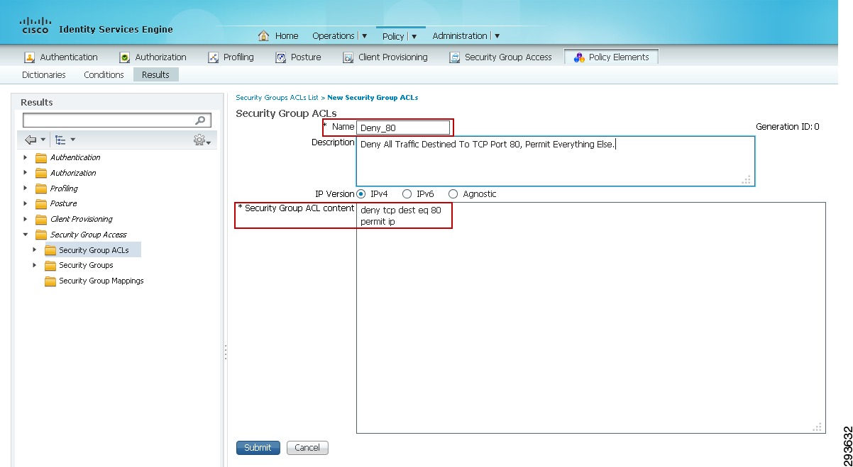
The basic TrustSec Policy that is used permits or denies a specific source SGT to a specific destination SGT. In addition to this basic policy it is possible to create SGACLs with additional granularity restricting or permitting access to specific TCP or UDP port numbers. Although not utilized in the CVD, the procedure for creating this policy is to first create an SGACL at ISE and then when creating a specific SGT policy, adding the SGACL to the definition. The following steps illustrate the creation of an optional SGACL to then be used in an SGT Policy.
1.
2.
3.
Figure 23-14 SGACL Creation
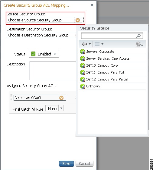
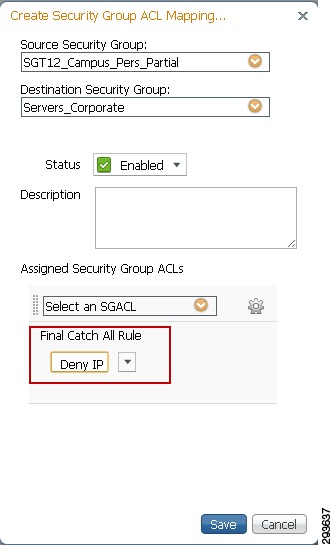
The next step is to define the SGT Policy on the ISE server by creating the appropriate entries to enforce the policy contained in Figure 23-13 earlier in this section. When creating the SGT Egress Policy definitions, it is possible to do this from three unique views:
•
•
•
Note that although the three views display the policy differently the steps for creating the policy are essentially the same. Please refer to the steps outlined below and depicted in Figure 23-15 where the Source Tree view is used.
4.
5.
6.
Figure 23-15 TrustSec Egress Policy Creation
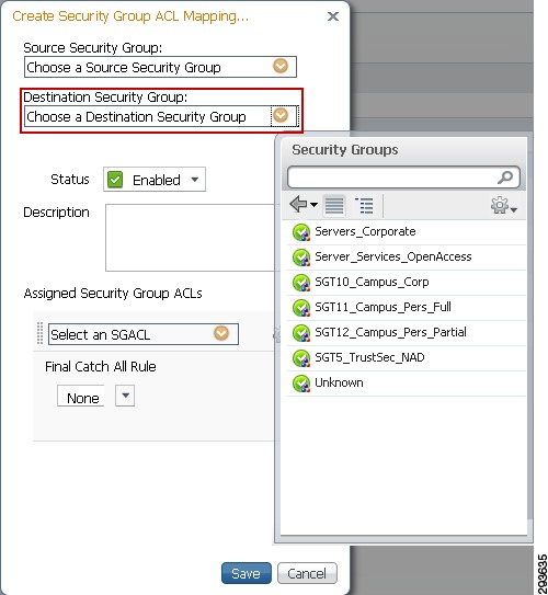
7.
Figure 23-16 TrustSec Egress Policy Creation Source SGT
8.
Figure 23-17 TrustSec Egress Policy Creation Destination SGT
9.
Figure 23-18 Enabling TrustSec Egress Policy with SGACL
10.
Figure 23-19 TrustSec Egress Policy Creation Denying Traffic
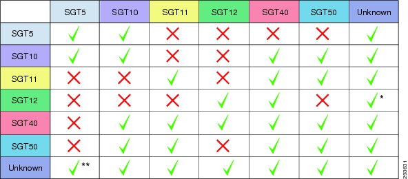
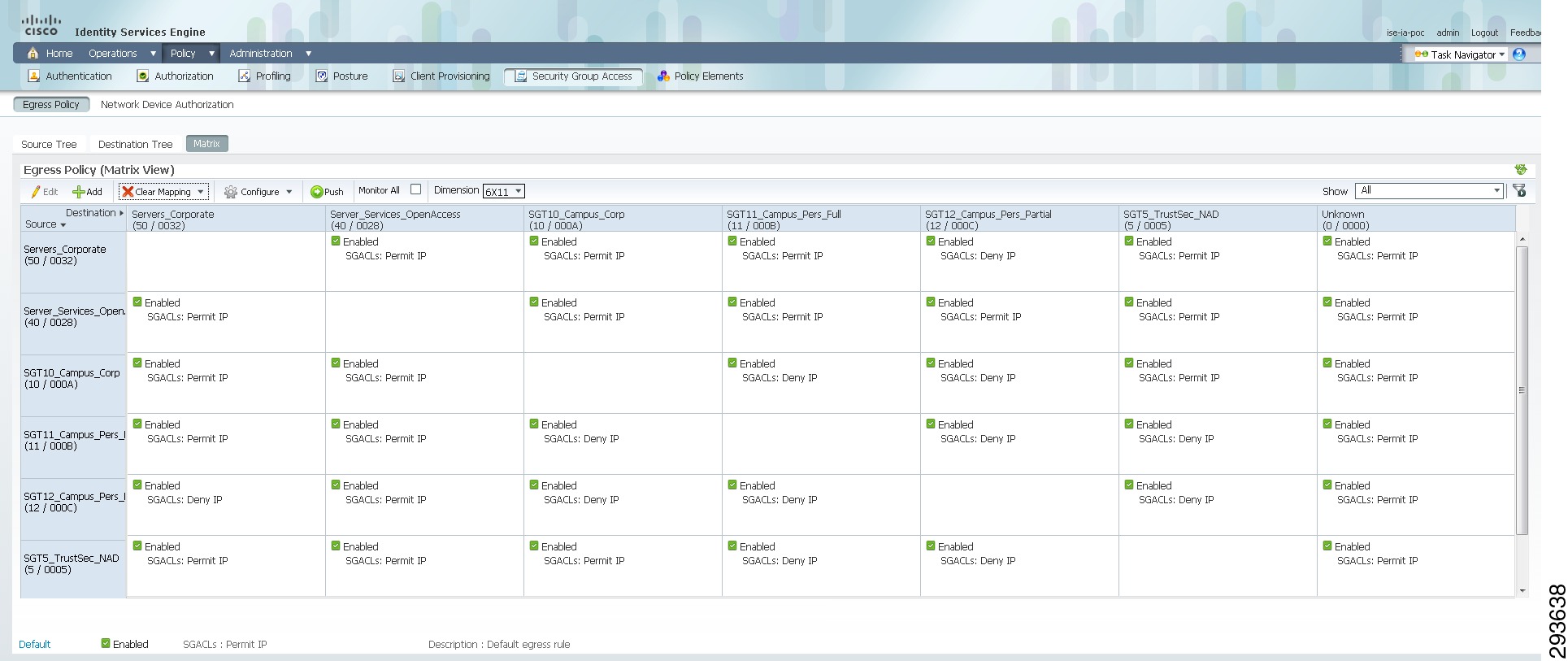
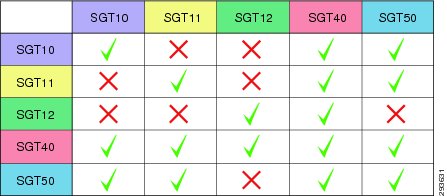
Once the addition of all egress policies is completed, the definitions can be viewed as a matrix as in Figure 23-20.
Figure 23-20 Egress Policy Matrix View
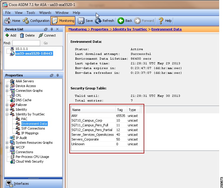
The following example output from the command show cts role-based permissions may be used to verify policies at a Catalyst 6500 once AAA configuration tasks have been completed later in this document.
ua28-6500-1#sh cts role-based permissionsIPv4 Role-based permissions default:Permit IP-00IPv4 Role-based permissions from group Unknown to group Unknown:Permit IP-00IPv4 Role-based permissions from group 10:SGT10_Campus_Corp to group Unknown:Permit IP-00IPv4 Role-based permissions from group 11:SGT11_Campus_Pers_Full to group Unknown:Permit IP-00IPv4 Role-based permissions from group 12:SGT12_Campus_Pers_Partial to group Unknown:Permit IP-00IPv4 Role-based permissions from group 40:Server_Services_OpenAccess to group Unknown:Permit IP-00IPv4 Role-based permissions from group 50:Servers_Corporate to group Unknown:Permit IP-00IPv4 Role-based permissions from group Unknown to group 40:Server_Services_OpenAccess:Permit IP-00IPv4 Role-based permissions from group 10:SGT10_Campus_Corp to group 40:Server_Services_OpenAccess:Permit IP-00IPv4 Role-based permissions from group 11:SGT11_Campus_Pers_Full to group 40:Server_Services_OpenAccess:Permit IP-00IPv4 Role-based permissions from group 12:SGT12_Campus_Pers_Partial to group 40:Server_Services_OpenAccess:Permit IP-00IPv4 Role-based permissions from group 40:Server_Services_OpenAccess to group 40:Server_Services_OpenAccess:Permit IP-00IPv4 Role-based permissions from group 50:Servers_Corporate to group 40:Server_Services_OpenAccess:Permit IP-00RBACL Monitor All for Dynamic Policies : FALSERBACL Monitor All for Configured Policies : FALSEConfiguring ISE for Network Access Device Authentication
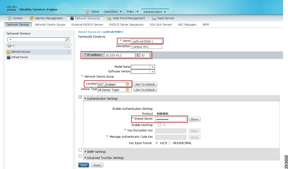
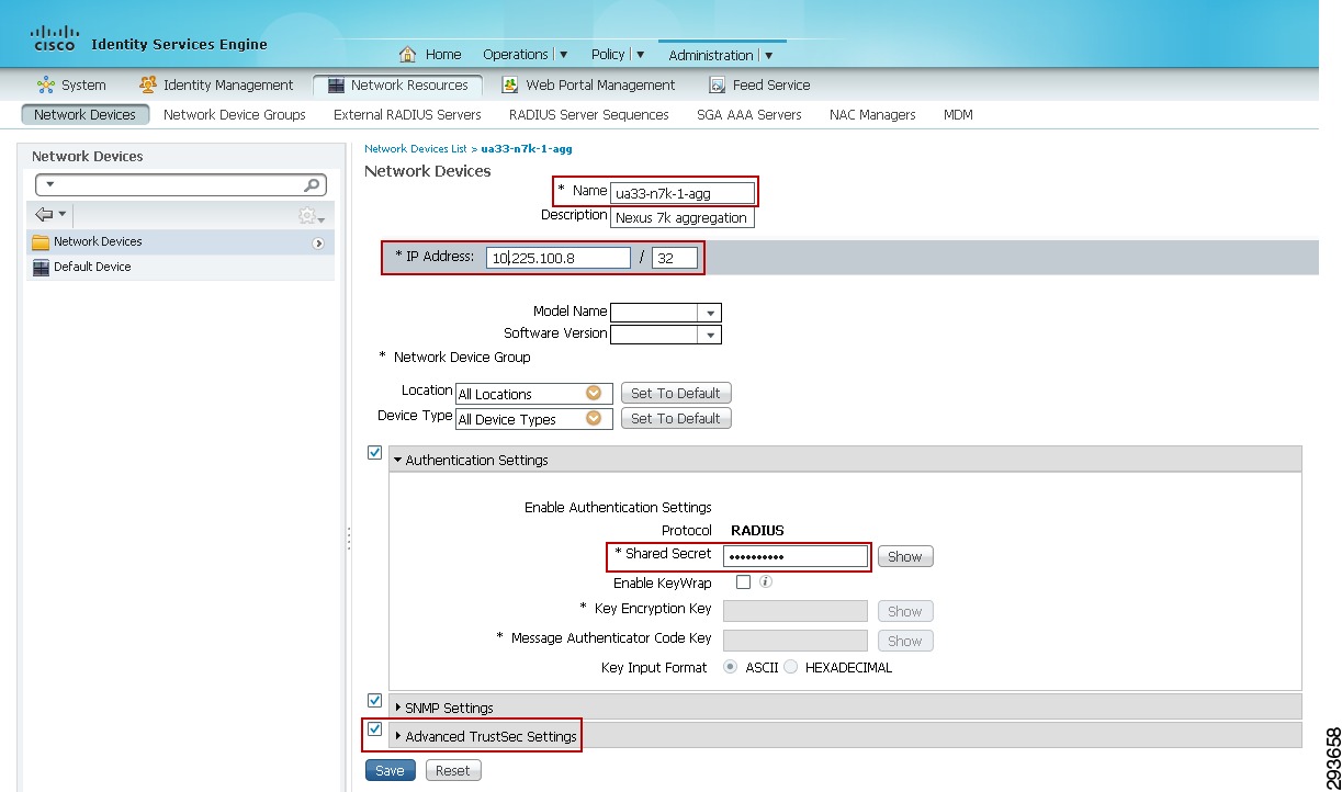
The next configuration task is to define the Network Devices that will be enforcing TrustSec Egress Policies in ISE and create the necessary AAA configuration on the devices. The purpose for doing this is to create a secure tunnel for EAP-FAST authentication of the device such that TrustSec environment data such as SG Names and associated SGT as well as TrustSec Egress Policies or SGACLs can be exchanged periodically. As discussed in the TrustSec Overview, this process is known as Network Device Admission Control or NDAC. As 802.1X will not be used to authenticate network devices across a link in order to build a trust relationship for SGT forwarding as well as MACsec encryption, it is only necessary to define those devices enforcing SGT policy as well as those wireless controllers serving as an 802.1X Authenticator to Supplicants on wireless devices attempting to Access the network. Therefore in Deployment Scenario 1 it will be necessary to create definitions for minimally five devices based on the infrastructure depicted in Figure 23-21.
Figure 23-21 Network Devices to be Defined in ISE
These devices are:
1.
2.
3.
4.
5.
As SGACLs will not be enforced at the data center Nexus 7000 Core switches nor the Catalyst 6500 VSS Core, it is not mandatory for these devices to be added to the Network Device List in ISE; the network device does not need to be defined in ISE to simply forward packets with an embedded SGT. It is however recommended to define these devices to accommodate future network changes or enforcement policies as well as define a device SGT to be used by traffic sourced by these switches. The following steps must be taken to define the network devices within ISE as depicted in Figure 23-22:
1.
2.
3.
4.
5.
6.
7.
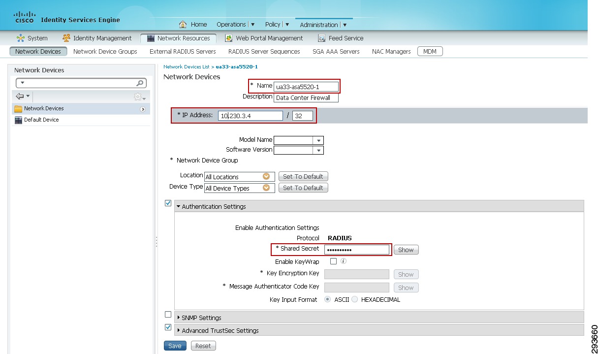
Figure 23-22 Network Device Generic Definition at ISE
Figure 23-23 Network Device Group definition
8.
9.
10.
11.
12.
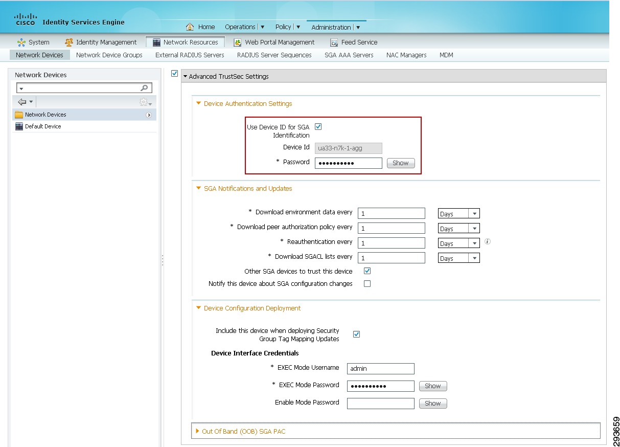
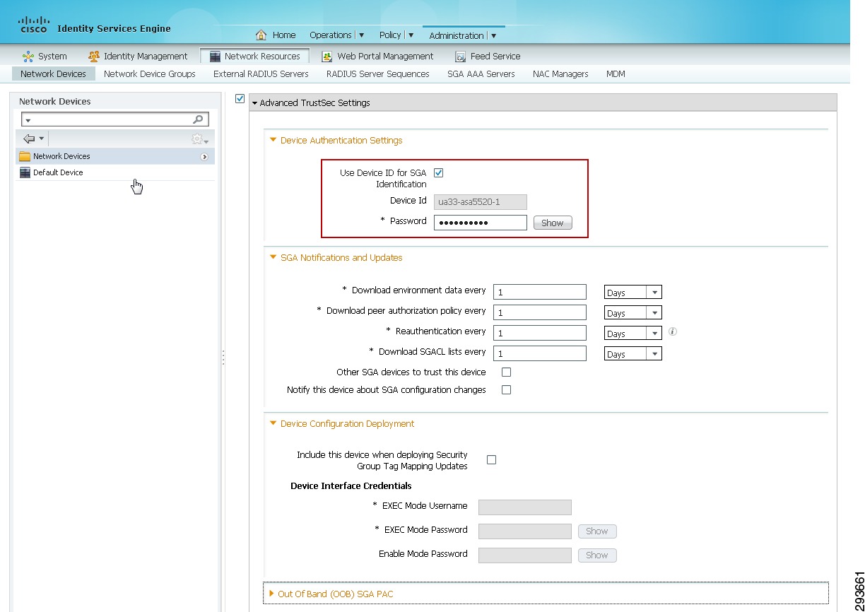
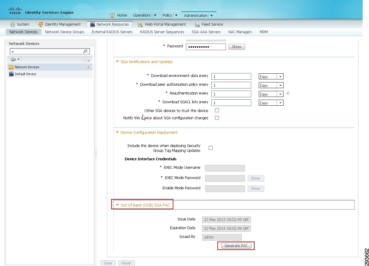
Figure 23-24 Network Device—Advanced TrustSec Settings
Configuring Network Devices with a Device SGT
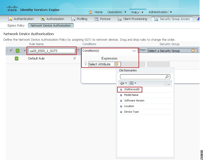
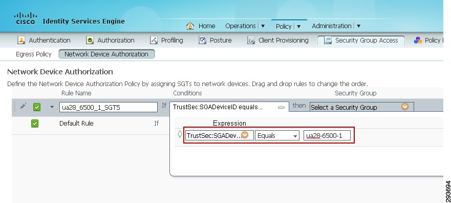
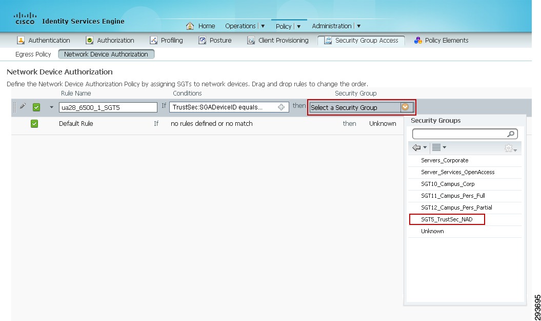
The following outlines the configuration steps required to define a device. Once a network device is configured for with a device SGT, any traffic sourced from that device will use the defined SGT. Note that assigning a Security Group Tag to a device is purely optional. Network devices in this CVD are assigned a device SGT of 5. As granular role-based policies using SGT are defined in the network, the assignment of an SGT to network devices will provide an additional level of control over whom or what may access the network infrastructure to poll or modify these devices.
1.
2.
3.
Figure 23-25 Configuring Network Device Authorization
4.
5.
6.
Figure 23-26 Defining Authorization Policy for the Network Device
7.
8.
Figure 23-27 Defining Network Device ID
9.
10.
Figure 23-28 Assigning the SGT to a Network Device
Configuring Network Access Devices for Authentication at ISE
Configuration of the network devices for NDAC support will be outlined in this section. A section will be devoted to each of the Wireless Controllers, Catalyst 6500 VSS and the Nexus 7000 switches.
The following configuration tasks will all be completed at the network devices themselves. This configuration is critical to identify the ISE Primary server as the AAA server from which information regarding TrustSec will be exchanged. Note that for greater resilience, multiple ISE Policy Service Nodes can be listed and will be tried in succession. As previously mentioned, it is only necessary to configure those devices that will provide access for the wireless users and the network devices that will actually enforce TrustSec policies. It is completely optional whether or not this needs to be configured on other devices in the path between the enforcement points.
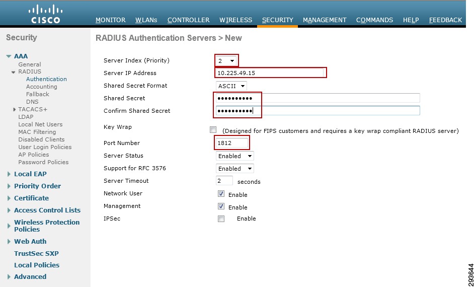
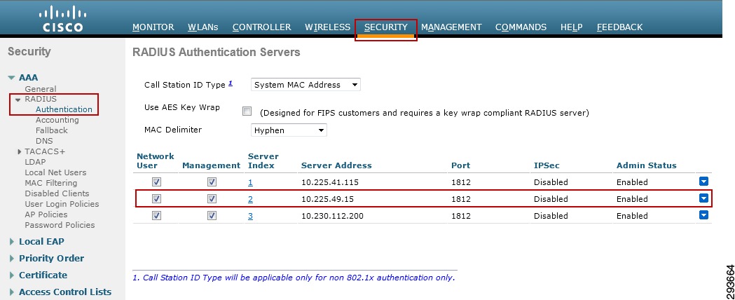
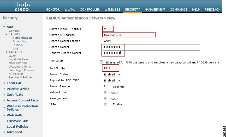
RADIUS Server Configuration on the Wireless Controller
The configuration of RADIUS server information is required in order for the controller to act as a RADIUS Authenticator for 802.1X-based authentication of wireless clients accessing the network. More than likely these steps have already been completed as this is a basic requirement for securing wireless access regardless of the desire to use ACLs or Security Group Tags.
1.
2.
3.
4.
Figure 23-29 Wireless Controller RADIUS Configuration
Figure 23-30 Wireless Controller RADIUS Server Configuration
5.
6.
7.
8.
9.
10.
Configuration of the wireless controller RADIUS server configuration is complete. Repeat these steps if additional controllers need to be configured.
Enabling TrustSec on the Catalyst 6500
TrustSec must be enabled both globally on the switch for SGT propagation as well as for those VLANs on which SGACLs will be enforced through the use of the following global commands:
cts role-based enforcement	/Globally enables SGACL enforcement for CTS-enabled Layer 3
interfaces in the system.
cts role-based enforcement vlan-list {vlan-ids | all} /Enables SGACL enforcement for Layer 2 switched packets and for L3 switched packets on an SVI interface.
Note
RADIUS Server Configuration on the Catalyst 6500
The following steps outline those tasks necessary to configure ISE as a RADIUS server at the Catalyst 6500. As discussed, this is to establish a secure connection with ISE for the exchange of TrustSec Environment Data and Policies. These steps should be performed on any Catalyst 6500 that will enforce policies based on Security Group Tags. For the infrastructure depicted in this CVD, configuration must be completed on the Catalyst 6500 VSS in Shared Services to which the wireless controllers are attached. As the Catalyst 6500 VSS serving as the Core of the network is merely forwarding tagged packets sourced from either the wireless users or servers themselves and not enforcing any policies, there is no requirement to configure it within ISE. The following provides the configuration commands required on the Catalyst 6500.
cts credentials id device-id password <password>	/TrustSec credentials for use with ISE;
device ID and password must be the same as at ISE.
aaa new-model /Enables AAAaaa group server radius <ise> /Creates a AAA Server Group ISEserver 10.225.49.15 auth-port 1812 acct-port 1813 /Defines 10.225.49.15 as a member of Group ISE.aaa authentication dot1x default group radius /Specifies the 802.1X port-based authentication method as RADIUS.aaa server radius dynamic-author /Enable CoA on the 6500 to enable updates for SG Names/Tags, Environment Data, and RBACLclient 10.225.49.15 server-key /Identifies ISE as AAA server initiating CoAaaa authorization network <ise> group radius /Configures the switch to use RADIUS authorization for all network-related service requests using server group <ise>.aaa accounting dot1x default start-stop group radius /Enables 802.1X accounting using RADIUScts authorization list <ise> /Specifies a Cisco TrustSec AAA server groupip radius source-interface Loopback0 /Matches the IP Address of the device configured in ISE; uses the IP Address of Lo0 to source all RADIUS.radius-server host 10.225.49.15 auth-port 1812 acct-port 1813 pac key <secret> /Specifies the RADIUS authentication server, shared secret must be same as configured for RADIUS secret at ISE.radius-server vsa send authentication platform /Configures the switch to recognize and use vendor-specific attributes (VSAs) in RADIUS Access-Requests generated by the switch during the authentication phasedot1x system-auth-control /Globally enables 802.1X port-based authenticationEnabling TrustSec on the Nexus 7000
As with the Catalyst 6500, TrustSec must be enabled for SGT propagation both globally on the switch as well as for those VLANs on which SGACLs will be enforced through the use of the following commands.
Global commands:
cts role-based enforcement /Enables SGACL enforcement on Nexus 7000.cts role-based counters enable /Enable role-based access control list (SGACL) counters.VLAN Interface commands:
(config)# vlan id /Enter VLAN configuration mode.(config-vlan)# cts role-based enforcement /Enables SGACL enforcement for specified VLAN.RADIUS Server Configuration on the Nexus 7000
The following steps outline those tasks necessary to configure ISE as a RADIUS server at the Nexus 7000. As discussed, this is to establish a secure connection with ISE for the exchange of TrustSec Environment Data and Policies. These steps should be performed on any Nexus 7000 that will enforce policies based on Security Group Tags. For the infrastructure depicted in this CVD, configuration must be completed on the Nexus 7000 Aggregation Switch in the data center. As the Nexus 7000 serving as the core of the data center is merely forwarding tagged packets sourced from either the wireless users or servers themselves and not enforcing any policies, there is no requirement to configure it within ISE.
On the Nexus 7000, enabling TrustSec is slightly different than on the Catalyst 6500 such that the 802.1X and TrustSec Features must be enabled on the Nexus platform through the following commands:
feature dot1x /Enable dot1x support.feature cts /Enable cts (TrustSec) supportOnce the features have been enabled the AAA servers and TrustSec Device credentials must be enabled through the following commands:
cts device-id device-id password password	/TrustSec credentials for use with ISE; device ID
and password much be the same as at ISE.
radius-server host 10.225.49.15 key <secret> pac /Specifies the RADIUS authentication server, shared secret must be same as configured for RADIUS secret at ISE.aaa group server radius <ise> /Creates a AAA Server Group ISEserver 10.225.49.15 /Defines 10.225.49.15 as a member of Group ISEaaa authentication dot1x default group <ise> /Specifies the 802.1X port-based authentication method as RADIUS.aaa accounting dot1x default group <ise> /Enables 802.1X accounting using group ISEaaa authorization cts default group <ise> /To configure the default authentication, authorization, and accounting (AAA) RADIUS server groups for Cisco TrustSec authorizationip radius source-interface loopback0 /Matches the IP Address of the device configured in ISE; uses the IP Address of Lo0 to source all RADIUS.Catalyst 6500 Platform Specific Considerations
Prior to discussing aspects of the TrustSec infrastructure configuration, it is necessary to highlight one aspect regarding the Catalyst 6500 when configured for Cisco TrustSec and specifically SG Tagging capability. As previously stated, the SUP2T and WS-X69xx series of linecards are the only SGT-Capable Supervisor and linecard available today for processing and imposition/removal of Security Group Tags in the Catalyst 6500. Specialized ASICs are required in order to forward tagged packets and encrypt the frames using 802.1ae MACsec with 10GE wirespeed performance. This functionality involves changes in the internal forwarding process. In order to support earlier linecards that do not have these newer ASICs (i.e. WS-X68xx, WS-X67xx, and WS-X61xx) in the same chassis when TrustSec has been enabled, two new operating modes have been developed called Ingress and Egress Reflector mode. Ingress Reflector mode is intended for use when the Catalyst 6500 is providing network access; it does not support linecards with a DFC installed. Egress reflector mode provides compatibility with legacy line cards by using the SUP2T forwarding engine's built-in packet replication ASICs to initiate a second packet forwarding decision. This second forwarding decision is used to impose the Cisco TrustSec SGT information on packets egressing the system from an SGT-capable interface. For purposes of the BYOD v2.5 CVD, Egress Reflector Mode will be used on the Catalyst 6500 VSS switches containing legacy linecards.
To enable the Egress Reflector Mode on the Catalyst 6500, it is necessary to perform a reload of the system. It is recommended for obvious reasons that this be performed off hours and that necessary precautions have been put in place to ensure that traffic can be forwarded around the reloading system if required. In the case of Catalyst 6500s configured for VSS, it is recommended that the entire system be reloaded through the reload command. The command to enable this mode of operation on the Catalyst 6500 is:
platform cts egressFor more detailed information, refer to: http://www.cisco.com/en/US/prod/collateral/switches/ps5718/ps708/white_paper_c11-658388.html.
Configuring Switching Infrastructure to Support TrustSec with 802.1ae MACsec Encryption
Now that the configuration of ISE and the Network Access Devices' ability to communicate with ISE as the AAA server via RADIUS have been completed, the following steps are required for the configuration of the 10GE links in the switching infrastructure to support TrustSec, specifically SGT insertion, removal, and forwarding as well as the encryption of those links using 802.1ae MACsec. In the BYOD CVD infrastructure depicted in Figure 23-31, it is necessary to configure the blue, 10GE links in the figure for TrustSec using the Catalyst and Nexus switch cts command.
Figure 23-31 TrustSec Configuration of 10GE Links
There are two methods, 802.1X Mode and Manual Mode, for configuring 10GE interfaces to support Security Group Access (TrustSec), enabling the forwarding and policy enforcement of frames with an embedded Security Group Tag. CTS 802.1X Mode uses a Pairwise Master Key (PMK) derived through the authentication phase between the network device and ISE for link encryption whereas with CTS Manual Mode, as its name implies, the PMK is manually configured. In this CVD, the Manual Mode of configuration is used.
Common to both of these methods is first the ability to employ MACsec (802.1ae) which provides encryption, a message integrity check, and data-path replay protection for links between adjacent network devices thereby protecting the CMD field and the SGT value it contains. Second, as previously discussed is the configuration for 802.1X authentication of the network devices that will enforce policies based on the SGT with ISE acting as an Authentication Server.
Also common to both CTS Manual and 802.1X Mode is the use of the Security Association Protocol (SAP) which is an encryption key derivation and exchange protocol based on a draft version of the 802.11i IEEE protocol. In a TrustSec configuration, the keys are used for MACsec link-to-link encryption between two interfaces.
In CTS Manual Mode, the Pairwise Master Key (PMK) will be manually configured on each of the two interconnecting 10GE interfaces with the sap pmk command. The PMK is a hexadecimal value with an even number of characters and a maximum length of 32 characters. It is not necessary to specify all 32 characters as the value provided will be padded with zeroes. This value MUST be the same on both sides of the link between the two switches. The Catalyst 6500s will pad the PMK provided with leading zeroes by default however the Nexus 7000 will pad the PMK with trailing zeroes by default. It is possible however, at the Nexus 7000 command line, to alter this behavior which is demonstrated below.
Note
When migrating port channels to enable TrustSec/MACsec, one possible migration option is to remove the links one at a time, configure TrustSec and MACsec as applicable on both sides of the link and ensure that the link comes back up. Repeat this on each port channel member until the last one is reached. Remove the last remaining member from the port channel. Once the port channel has no remaining links, those configured for TrustSec can then be added sequentially. This type of migrational procedure can be used on both the Catalyst and Nexus switching platforms.
Additionally, for manual mode, a "trust" relationship must be established for device peers within the TrustSec domain through the configuration of a policy on the interface. This is only necessary on the Catalyst 6500 as the Nexus 7000 by default trusts the tags forwarded by its peer. As the default for the Catalyst 6500 is "untrusted", if this policy is not created on the Catalyst 6500 interfaces, the tags embedded in frames sourced from its peer or propagated through the peer will be untrusted and removed and the frame forwarded un-tagged. This policy is established through the use of the policy static sgt id trusted command.
Note
Table 23-2 documents these behaviors.
Note
Catalyst 6500 Commands
At the Ten Gigabit Ethernet interface configuration prompt issue the following.
(config-if)#cts manual /Manually enable an interface for Cisco TrustSec Security (CTS)(config-if-cts-manual)# sap pmk ABC123 mode-list gcm-encrypt gmac null /Manually specify the Pairwise Master Key (PMK) and the Security Association Protocol (SAP) authentication and encryption modes to negotiate MACsec link encryption between two interfaces.(config-if-cts-manual)# policy static sgt id trusted /Establishes the trust state of the peer interface. See note above.When configuring the Security Association Protocol as the keying mechanism for use with MACsec several options are available for authentication and encryption on the link. Table 23-3 provides a summary of each option. When mode-list is specified as above, the devices on either side of the link will negotiate via the SAP protocol, the method supported. As defined above, gcm-encrypt will be tried first and so on.
Table 23-3 Security Association Protocol Options
gcm-encrypt
Authentication and encryption
gmac
Authentication, no encryption
no-encap1
No encapsulation1
null
Encapsulation (SGT), no authentication or encryption
1 If the interface is not capable of SGT insertion or data link encryption, no-encap is the default and the only available SAP operating mode.
Nexus 7000 Commands
At the Ten Gigabit Ethernet interface configuration prompt issue the following. If this configuration is being applied to a link interconnecting a Catalyst 6500 and a Nexus 7000 note that it will be necessary to alter the <sap pmk> command to change the default method of padding the PMK should less that 32 characters be specified. As noted earlier in the Catalyst 6500 interface configuration, it is unnecessary to specify the trust state of the peer through the use of interface command <policy static> as the default is trusted on the Nexus 7000.
(config-if)#cts manual /Manually enable an interface for Cisco TrustSec Security (CTS)Link connecting to another Nexus switch:
(config-if-cts-manual)# sap pmk ABC123 mode-list gcm-encrypt gmac null /Manually specify the Pairwise Master Key (PMK) and the Security Association Protocol (SAP) authentication and encryption modes to negotiate MACsec link encryption between two interfaces.Link connecting to a Catalyst switch:
(config-if-cts-manual)# sap pmk ABC123 left-zero-padded mode-list gcm-encrypt gmac null
/Manually specify the Pairwise Master Key (PMK) and the Security Association Protocol
(SAP) authentication and encryption modes to negotiate MACsec link encryption between two
interfaces.
The SAP modes of operation are identical to those of the Catalyst 6500 detailed earlier.
Configuring Security Group Tag Exchange Protocol (SXP) for Wireless Controllers
Campus wireless users accessing the network upon successfully matching an authorization profile at the Identity Services Engine will be associated with an SGT. Upon successful authentication and subsequent authorization to the network the Identity Services Engine will pass the appropriate SGT value to the wireless controller through a RADIUS AV. This SGT value is associated with the IP Address of the wireless user obtained through the 802.1X authentication and an IP/SGT mapping/mapping created at the wireless controller.
Wireless controllers such as the CT5508, used in this guide, and the WiSM2 however, do not support the tagging of packets sourced from these wireless users out of the controller through both physical and internal interfaces, in the case of the WiSM2. As such, the Security Group Tag Exchange Protocol will be used to advertise these SGT mappings to the Shared Services Catalyst 6500VSS switch which will impose the appropriate tag upon egress from the switch.
SXP is configured on a device by identifying its peer's IP Address and specifying a password for use in authenticating each side of the connection. SXP supports two modes which can be used either exclusively or combined. The first mode is that of the "Speaker" which as the name suggests advertises IP/SGT mappings. The other mode is "Listener" which also as its name suggests, listens for the Speaker's advertisements. It is possible for a device to be both a "Speaker" and a "Listener". The CT5508 and WiSM2 obviously only support "Speaker" mode as they do not support SGACLs or SGT Tagging and hence a "Listener" mode is not applicable.
Both sides of the SXP connection must be configured and with Deployment Scenario 1, includes configuration at both of the CT5508s as well as the Shared Services Catalyst 6500 VSS switch. Please refer to Figure 23-32.
Figure 23-32 SXP Peering
Wireless Controller Configuration
Access the wireless controller via a web UI and follow the following steps:
1.
The screen in Figure 23-33 appears.
2.
3.
4.
5.
6.
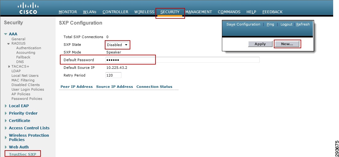
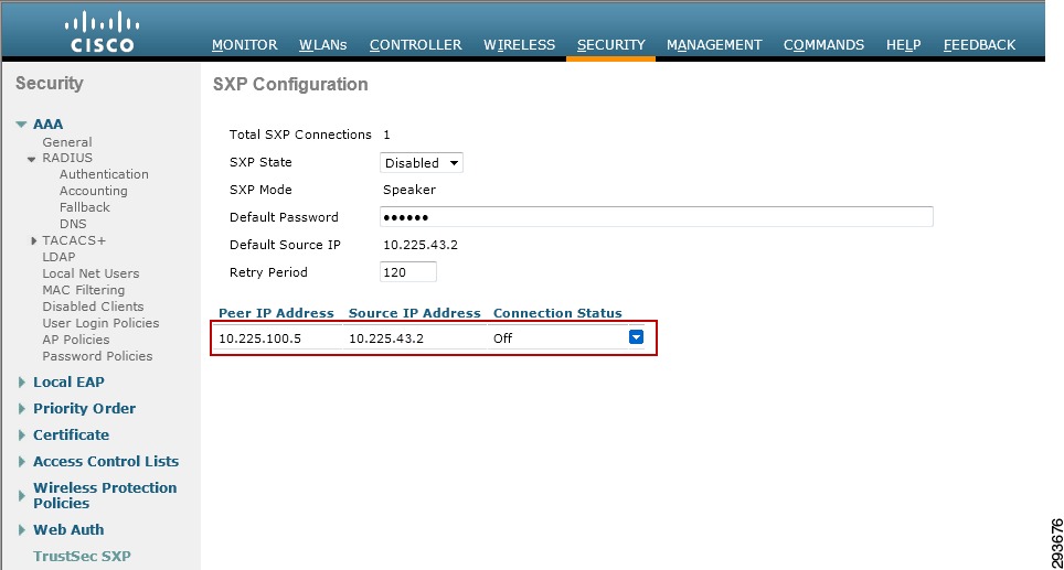
Once successfully configured, the screen in Figure 23-34 should be presented upon accessing Security > TrustSec SXP. The "Connection Status" will indicate "Off" until the other device is configured.
Figure 23-33 SXP Configuration at Wireless Controller
Figure 23-34 SXP Configuration Complete
Catalyst 6500 SXP Configuration
The following commands were used at the Shared Services Catalyst 6500 VSS to enable SXP peering with the CT5508 wireless controllers.
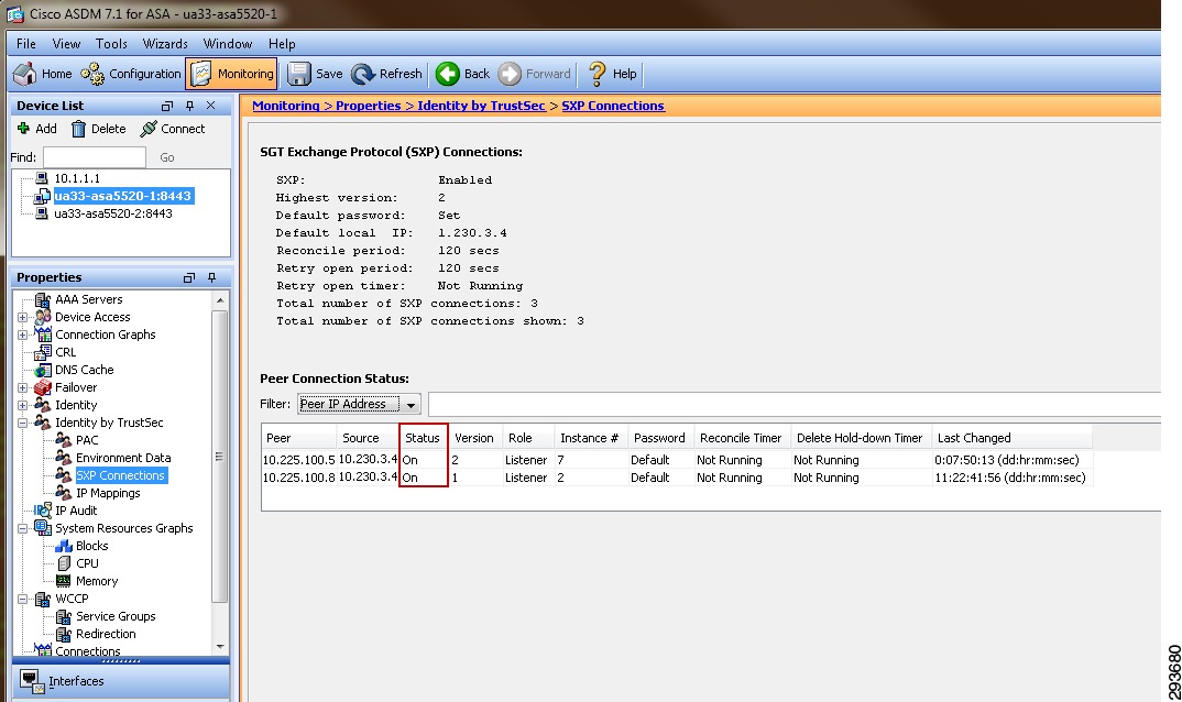
cts sxp enable /Enable CTScts sxp default source-ip 10.225.100.5 /Source SXP connection from 10.225.100.5 (Lo)cts sxp default password password /Configured password on the 6500 for incoming SXP connectionscts sxp connection peer 10.225.43.2 source 10.225.100.5 password default mode local listener hold-time 0 0 /Builds an SXP connection to its peer at 10.225.43.2 using source address of 10.225.100.5 and the default password defined above. Specifies that this (local) device is in "Listener" mode. The source IP Address used here is purely optional as it was specified above.Issuing the command show cts sxp connection results in the following output.
ua28-6500-1>sh cts sxp connectionsSXP: EnabledHighest Version Supported: 4Default Password : SetDefault Source IP: 10.225.100.5Connection retry open period: 120 secsReconcile period: 120 secsRetry open timer is not running----------------------------------------------Peer IP: 10.225.43.2 <--Wireless ControllerSource IP: 10.225.100.5Conn status: OnConn version: 2Local mode: SXP ListenerConnection inst#: 1TCP conn fd: 1TCP conn password: default SXP passwordDuration since last state change: 0:21:49:55 (dd:hr:mm:sec)Total num of SXP Connections = 1Configuring Static IP/SGT Bindings on Nexus Switches
Unlike campus access through Catalyst Switches and Cisco Wireless Controllers where dynamic SGT mappings are communicated and created through 802.1X and RADIUS exchange, the vast majority of organizations do not implement 802.1X for server connectivity. As such, data center switches such as the Cisco Nexus switches provide only limited support for the use of 802.1X and do not specifically support an SGT RADIUS AV as an option. Therefore, IP Address to SGT mappings will be manually defined for bare metal and virtual servers.
For purposes of this CVD we have defined our IPtoSGT Bindings at the Nexus 7000 Data Center Aggregation layer switches as depicted below. Note that as there are two Nexus 7000s comprising the aggregation layer in the data center, both must be configured identically for consistent policy enforcement.
The following commands provide an example of these:
cts role-based sgt-map 10.230.4.2 40 /Binds 10.230.4.2 to SGT 40cts role-based sgt-map 10.230.4.22 40 /Binds 10.230.4.22 to SGT 40cts role-based sgt-map 10.230.5.2 50 /Binds 10.230.5.2 to SGT 50cts role-based sgt-map 10.230.6.2 40 /Binds 10.230.6.2 to SGT 40cts role-based sgt-map 10.230.7.2 50 /Binds 10.230.7.50 to SGT 50To verify the IP/SGT mappings at the Nexus 7000, issue the command sh cts role-based sgt-map.
IP ADDRESS SGT VRF/VLAN SGT CONFIGURATION10.225.49.15 40 vrf:1 CLI Configured10.225.42.15 40 vrf:1 CLI Configured10.230.1.45 40 vrf:1 CLI Configured10.230.1.46 40 vrf:1 CLI Configured10.230.4.2 40 vrf:1 CLI Configured10.230.4.22 40 vrf:1 CLI Configured10.230.5.2 50 vrf:1 CLI Configured10.230.6.2 40 vrf:1 CLI Configured10.230.7.2 50 vrf:1 CLI ConfiguredA key concept to be considered when granting access to the data center is that of the SGT value of zero or "Unknown" as it is referred to. If the IP Address of a server has not been mapped to an SGT at the point of enforcement such as the Nexus 7000 in the data center, that server would be considered Unknown and associated with SGT0. Unlike ACLs with an implicit deny at the end, SGACLs when implemented on a switching platform have an implicit permit to Unknown or all; this is not true on the ASA or IOS ZBFW acting as a SG-FW where an implicit deny is still maintained. Hence on a switch, if there is not a specific tag value assigned to a server, the destination is considered Unknown (SGT0) and the packet forwarded. This SGT0 thus allows a migrational approach to tag assignment in the data center.
In a BYOD setting where personal or contractor assets are permitted on the network and only partial access to data center resources is permitted through the use of SGACLs on the switching infrastructure, the task of assigning an SGT to every data center asset will likely prove daunting when first migrating to the use of Security Group Tags as it is not possible to create a switch-based SGACL using both SGT and IP addresses; the destination SGT of the device must be known. Hence it is with this in mind that the concept of the Unknown tag may be used to provide a phased approach to SGT assignment. Throughout the campus infrastructure the default policy permitting any SGT to "Unknown" is left unaltered. However, at the Nexus 7000 Data Center Aggregation switches where policies based on SGACLs are enforced, an explicit deny of a given source SGT to "Unknown" can be created. Using this premise one could easily identify and provide a tag for those servers where open access is permitted. These devices with partial access can get to them, but if a tag doesn't exist for any other server they are attempting to access (unknown) the SGACL will deny access. As servers that only some users or other servers should be able to access are associated with a SGT, new policies can be defined restricting that access.
A policy that is explicitly (manually) configured at a networking device will take precedence over a policy that is dynamically received from ISE. Hence By defining this SGACL at these data center aggregation switches only, these partial access devices are permitted access to Unknown anywhere else in the network except in these data center switches.
The following commands configure the SGACL locally on the Nexus 7000 Data Center Aggregation switches:
cts role-based access-list block12toUnk /Creates an SGACL "block12Unk"deny ip /Action performed by SGACL "block12Unk"cts role-based sgt 12 dgt 0 access-list block12toUnk /Manually configure mapping of Cisco TrustSec Security Group Tags (SGTs) to a security group access control list (SGACL). Defines source SGT12 to destination SGT0 (Unknown)To verify the role-based access policy at the Nexus 7000, issue the command sh cts role-based policy. The following is an excerpt of the entire output showing the previously denied SGACL.
ua33-n7k-1-agg# sh cts role-based policysgt:10dgt:unknown rbacl:Permit IPpermit ipsgt:11dgt:unknown rbacl:Permit IPpermit ipsgt:12dgt:unknown rbacl:block12toUnkdeny ipsgt:anydgt:any rbacl:Permit IPpermit ipThis completes the configuration for Deployment Scenario 1. The next steps are to configure the actual user policies as defined in Chapter 16 "BYOD Limited Use Case—Corporate Devices" for corporate devices and Chapter 15 "BYOD Enhanced Use Case—Personal and Corporate Devices" for personal devices.
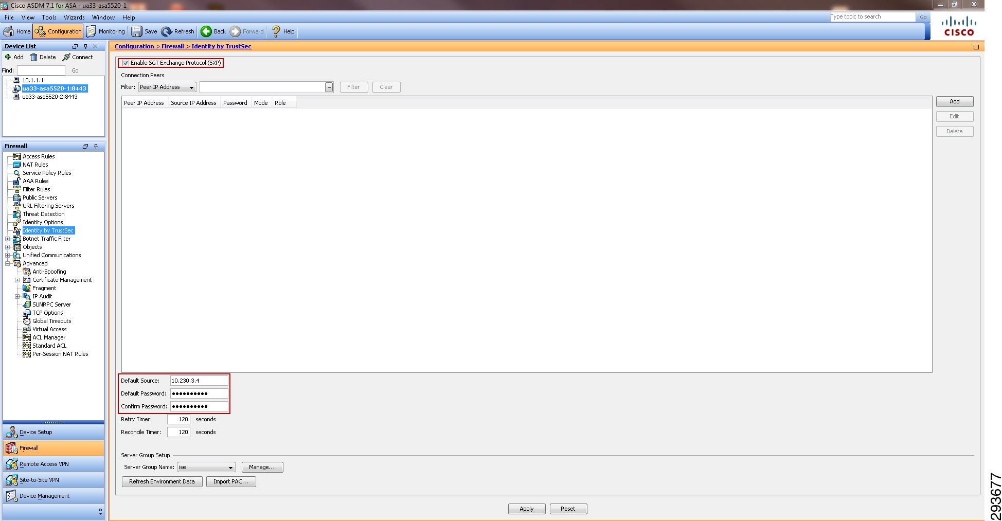
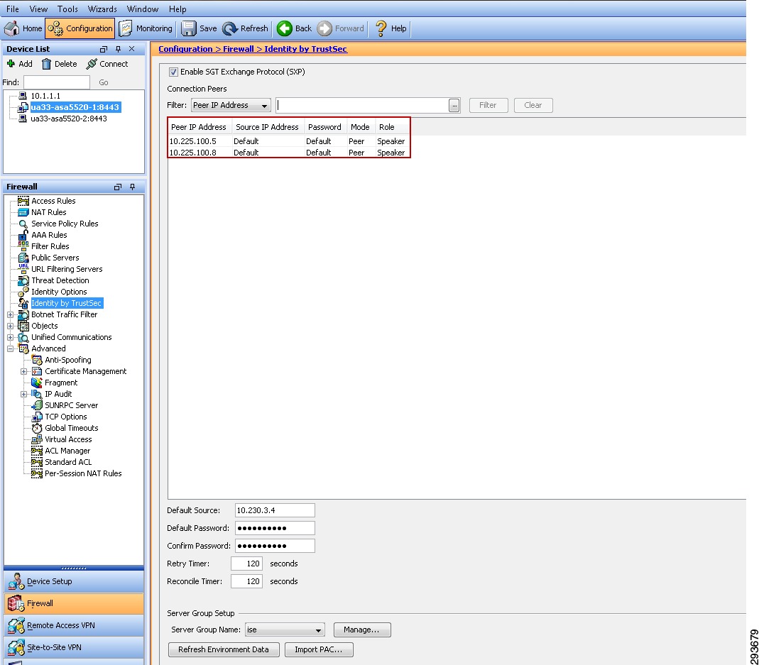
TrustSec Policy Configuration Using the ASA and Security Group Firewall in the Data Center—Deployment Scenario 2
For the topology used in Deployment Scenario 2, see Figure 23-35.
Figure 23-35 Deployment Scenario 2 Configuration
With Deployment Scenario 2 an alternate means other than SGACLs will be used to enforce TrustSec policy. In Scenario 2 an ASA running version 9.0(2) will be used as a Security Group Firewall (SG-FW) securing data center resources from outside access. Unlike Scenario 1, the 10GE infrastructure between the Shared Services Catalyst 6500 VSS and the data center does not need to be enabled to support Security Group Tag forwarding or SGACLs. As the ASA does not presently support native SGT tagging on its Ethernet interfaces, Security Group Tag Exchange Protocol (SXP) must be used for it to learn IP/SGT mappings from other areas of the network where they have been dynamically learned or statically configured. It is by virtue of these SXP advertisements that the ASA is capable of inspecting the untagged traffic and, through the use of these IP/SGT mappings, that SG-FW policies are enforced
As in the case of the first deployment scenario, wireless users, upon successful authentication and authorization, will be associated with a specific role and an IP to SGT Binding will be created on the wireless controller with the device's IP Address and the appropriate SGT. SXP will be used to communicate this mapping to the Shared Services Catalyst 6500s to which the wireless controllers are attached. SXP will then be used to re-advertise the mappings the Shared Services Catalyst 6500 VSS has learned from the wireless controllers to the ASA firewall. In addition to the SXP Peering between the Shared Services 6500s and the ASA, the Nexus 7000 aggregation switches will also require an SXP Peering with the ASA firewall to advertise SGT mappings that have been statically configured on them.
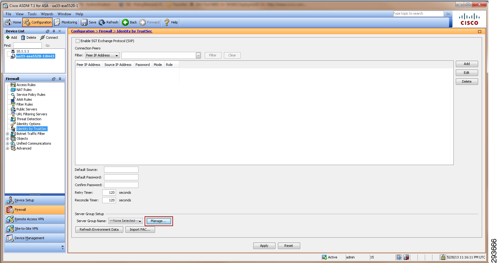
As previously discussed, the ASA firewall that will be used to enforce SG-FW policies must be manually configured with SGT policies as dynamic updates via ISE is presently not supported in the ASA. The details regarding these SG-FW policies will be discussed later.
As wireless traffic egresses the Shared Services Catalyst 6500s en route to the data center, the traffic will be untagged and will simply pass through the Core, enter the data center switching infrastructure, and ultimately arrive at the ASA firewall where the appropriate SG-FW policy will be enforced.
In the unlikely event that any traffic would be sourced from a server in the data center, it would likewise egress the Nexus 7000 aggregation switch untagged and be forwarded to the ASA firewall where any applicable SG-FW policy will be enforced.
Figure 23-36 depicts the infrastructure used in Deployment Scenario 2 and the means by which security group policies will be enforced.
Figure 23-36 TrustSec Policy Enforcement Using SXP and SG-FW
The following major tasks will be required for this deployment scenario and outlined in the following sub-sections:
1.
2.
3.
a.
b.
c.
4.
a.
b.
c.
5.
6.
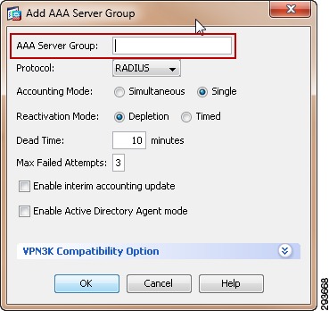
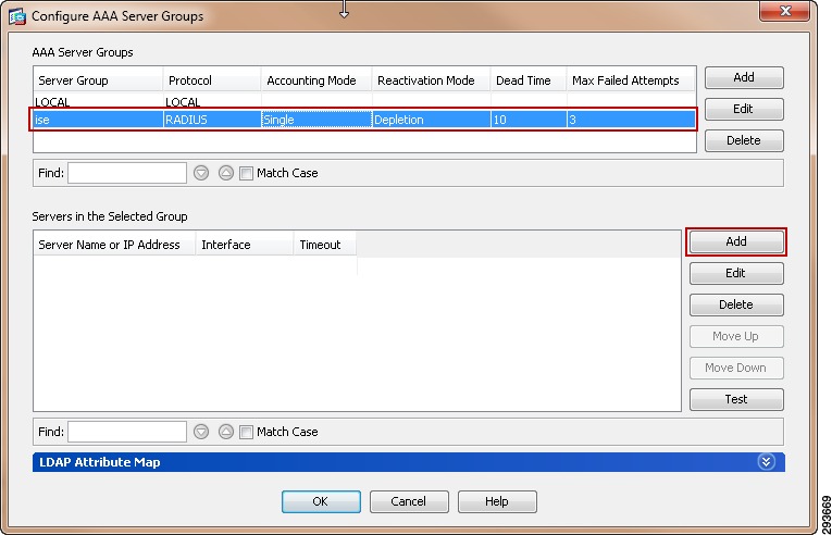
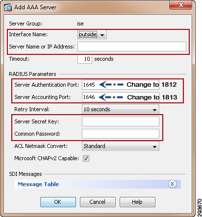
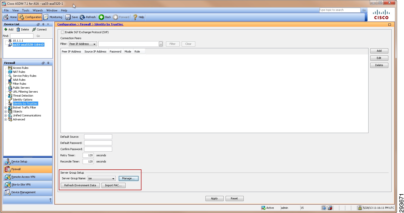
Configuring ISE to Support TrustSec
For Deployment Scenario 2, the ISE configuration required to define the Security Group Tag value/name remains the same as previously described for Scenario 1. However, it will be necessary to configure the ASA SG-FW policy manually at the ASA as there is no NDAC support for acquiring TrustSec egress policies cannot be learned dynamically. As such, unlike Deployment Scenario 1, it is unnecessary to configure the actual policies to be enforced at ISE; only the SG Names or Tables as they are commonly referred to. This will be addressed in an upcoming section.
For Cisco ISE to function as a Security Group Access (TrustSec) server and provide TrustSec services, you must define the following, global TrustSec settings. The first step is to define ISE as an TrustSec AAA server as depicted in Figure 23-37.
1.
2.
3.
4.
Figure 23-37 ISE TrustSec Server AAA Definition
The next step is to configure TrustSec Server Protected Access Credential (PAC) Time-to-Live settings and SGT reservations.
The tunnel PAC generates a tunnel for the EAP-FAST protocol and is used for Secure RADIUS communications with Network Devices for TrustSec environmental data. Unlike other networking devices such as Catalyst and Nexus switches, a new PAC must be manually re-generated and reapplied for the ASA prior to expiration; this will be discussed in the following ASA section as well.
By default Security Group Tags are dynamically assigned a decimal/hex value in ascending order by ISE. It is possible to change this behavior such that all tags must be manually defined or to reserve a range that can be specifically allocated to users, devices, or servers, In the CVD, a range of SGT values will be reserved for allocation among users/Devices and servers. Figure 23-38 depicts the reservation of Tags 5 through 80 for use in the CVD.
To complete this step:
1.
2.
3.
4.
5.
Figure 23-38 TrustSec Servers Settings in ISE
The next step is to define Security Group Tag names and associate them with a numerical value at the Identity Services Engine. The SGT names are periodically pushed to the Network Access Device (NAD) through periodic updates or upon that network device's authentication (NDAC Authentication) with ISE. They may also be manually pushed as well.
To complete this step as depicted in Figure 23-39:
6.
7.
8.
9.
10.
Figure 23-39 Security Group Creation
In BYOD v2.5, Table 23-4 shows the SGT Names and corresponding Tag Values used.
Note
Figure 23-40 depicts all of the security group names defined in ISE for this CVD.
Figure 23-40 Security Groups Used in CVD
Configuring ISE for Network Access Device Authentication
Network device definitions for the wireless controllers, Nexus switches, and the ASA firewall must be created in ISE for Deployment Scenario 2. Each of the two controllers will need to be defined in ISE as both are active, however as the ASA firewalls are running in an Active/Standby HA mode, only the primary firewall needs to be defined in ISE. These devices are depicted in Figure 23-41 and are:
1.
2.
3.
4.
5.
Figure 23-41 Network Devices to be Defined in ISE for Scenario 2
Wireless Controller Configuration
In this deployment scenario, it is necessary to define the wireless controllers as they will serve as 802.1X Authenticators for the wireless devices accessing the network. As such, the controllers upon a device's successful authentication and authorization will within a RADIUS exchange with ISE, receive the appropriate SGT value to be associated with that device's IP Address. More than likely, wireless controllers will likely have already been defined for 802.1X wireless access regardless of the use of SGT or ACLs for enforcing policies. In step 4 below however, we have suggested the additional use of Network Device Location for use within Authorization policies.
The following steps must be taken to define the wireless controllers within ISE as depicted in Figure 23-42; the ASA specific configuration will follow separately:
1.
2.
3.
4.
5.
6.
7.
Note that it is unnecessary to complete the Advanced TrustSec Settings for CT5508 or WiSM2 wireless controllers. These controllers are not capable of supporting anything other than the creation of IP Address to SGT mapping and advertising those mappings to manually configured peers via the SXP protocol. These settings are only used for those devices supporting SGACLs and Native SG Tagging on SGT-capable hardware requiring the download of TrustSec environmental and policy data from ISE.
Figure 23-42 Wireless Controller Definition at ISE
Figure 23-43 Network Device Group Definition
This completes the Network Device Definition for the wireless Controllers in ISE.
Nexus 7000 Configuration
Although SGACLs will not be enforced at the Nexus 7000 Data Center Aggregation switches as in the first deployment scenario, but rather at the ASA configured as a Security Group Firewall, it is still necessary to define the Nexus 7000 aggregation switches in ISE in order to share TrustSec Environment Data in order to learn SG Names and IP/SGT mappings defined centrally at ISE. Note that for the purposes of the CVD, all IP/SGT mappings will be statically configured on the Nexus 7000 aggregation switches as in the first deployment scenario. The following steps must be taken to define the Nexus 7000 Data Center Aggregation switches within ISE as depicted in Figure 23-44:
1.
2.
3.
4.
5.
Figure 23-44 Nexus 7000 Generic Definition at ISE
6.
7.
8.
9.
Figure 23-45 Nexus 7000 TrustSec Definition at ISE
ASA Firewall Configuration
Once the wireless controllers and Nexus switches have been defined in ISE, the ASA firewall will be defined next. Whereas Catalyst and Nexus switches can import the PAC file from ISE when authenticating for the first time, The ASA firewall requires that this process be performed manually. Importing the PAC file to the ASA establishes a secure communication channel with ISE. After the channel is established, the ASA initiates a PAC secure RADIUS transaction with ISE and downloads Cisco TrustSec environment data; specifically, the ASA downloads the security group table. As discussed earlier, the ASA firewall does not download SGT Policies only the SG tables; the SGT policies will be manually defined at the ASA. The security group table maps SGTs to security group names. Security group names are created on ISE and provide user-friendly names for security groups.
The first time the ASA downloads the security group table, it walks through all entries in the table and resolves all the security group names contained in security policies configured on the ASA; the ASA then activates those security policies locally. If the ASA is unable to resolve a security group name, it generates a system log message for the unknown security group name.
One special consideration needs to be kept in mind regarding the ASA and that is if PAC expiration occurs, a new PAC file will not be automatically downloaded as in the case of Catalyst and Nexus switches and hence updated SGT tables will not be able to be downloaded. At the time of this writing (v9.0.2), a new PAC file must be imported manually prior to the expiration of the existing one. If the ASA cannot download an updated security group table, the ASA continues to enforce security policies based on the last downloaded security group table until a new PAC file is downloaded and the ASA downloads an updated table.
The following steps must be completed to define the ASA firewall within ISE as depicted in Figure 23-46:
1.
2.
3.
4.
5.
Figure 23-46 ASA Network Device General Settings in ISE
Next complete the following steps for TrustSec configuration as depicted in Figure 23-47:
6.
7.
8.
9.
Figure 23-47 ASA TrustSec Settings in ISE
The final task at ISE is to generate an Out of Band PAC for subsequent importing at ISE as depicted in Figure 23-48:
10.
11.
A popup will appear as depicted in Figure 23-49.
The device identity will be pre-populated using the "Device ID for TrustSec" hostname.
12.
13.
14.
A PAC File will now be generated and you will be prompted to download and save the PAC file locally for later import and use by the ASA firewall.
Figure 23-48 Generating the TrustSec PAC File for the ASA Firewall at ISE
Figure 23-49 TrustSec PAC File Definition for the ASA Firewall at ISE
This completes the Network Device Definition for the ASA firewall in ISE.
Configuring the Network Devices for Integration with ISE
The following configuration tasks will all be completed at the network devices themselves. This configuration is critical to identify the ISE Primary server as the AAA server from which information regarding TrustSec will be exchanged. Note that for greater resilience, multiple ISE Policy Service Nodes can be listed and will be tried in succession. As previously mentioned, it is only necessary to configure those devices that will provide access for the wireless users and the network devices where static IP/SGT mappings will be defined.
RADIUS Server Configuration on the Wireless Controller
The configuration of RADIUS server information is required in order for the controller to act as a RADIUS Authenticator for 802.1X-based authentication of wireless clients accessing the network. More than likely these steps have already been completed as this is a basic requirement for securing wireless access regardless of the desire to use ACLs or Security Group Tags.
1.
2.
3.
A new window will open as seen in Figure 23-51.
Figure 23-50 Wireless Controller RADIUS Configuration
Figure 23-51 Wireless Controller RADIUS Server Configuration
4.
5.
6.
7.
8.
9.
Configuration of the wireless controller RADIUS server configuration is complete. Repeat these steps if additional controllers need to be configured.
RADIUS Server Configuration on the ASA Firewall
The following configuration steps need to be completed in order to establish the ISE server as a AAA server for the ASA and importing the TrustSec PAC File used for secure RADIUS exchange of TrustSec Environment Data and the SGT Tables specifically.
1.
2.
3.
Figure 23-52 AAA Server Configuration in ASA
A popup window will open as can be seen in Figure 23-53.
4.
Figure 23-53 Configuring AAA Server Groups in ASDM
A popup window opens as seen in Figure 23-54.
5.
6.
Figure 23-54 Adding AAA Server Group in ASA
Once OK has been clicked the popup window closes and the "Configure AAA Server Groups" window is populated with the new Server Group as seen in Figure 23-55.
7.
Figure 23-55 Adding AAA Server to Server Group in ASA
A popup window opens as seen in Figure 23-56.
8.
9.
10.
11.
12.
13.
Figure 23-56 Adding AAA Server to Server Group
Once the AAA Server Group has been defined it will now be necessary to import the TrustSec PAC File at the ASA firewall. As depicted in Figure 23-57:
14.
15.
A popup window will open as seen in Figure 23-58.
16.
Figure 23-57 Importing TrustSec PAC File at ASA
Figure 23-58 Importing TrustSec PAC at ASA
These final steps should be taken to validate that the PAC file was imported correctly at the ASA and that the SGT Tables have been downloaded from ISE. Issue the show cts pac command at the ASA firewall. The output should be as shown in Example 23-1.
Example 23-1 ASA show cts pac Output
ua33-asa5520-1/pri/act# show cts pacPAC-Info:Valid until: May 29 2014 21:01:35AID: 46094036746cf4dee55688b595c61925I-ID: ua33-asa5520-1A-ID-Info: Identity Services EnginePAC-type: Cisco TrustsecPAC-Opaque:000200b8000300010004001046094036746cf4dee55688b595c619250006009c000301003104b1f4305546ff989c2e4dae291af500000013519faef000093a804ee94210ca6a4b1b5404baaa22eb122daa3f6bf5cdcbb5d19939191f6c10dab85ee437b842716e801cf2d1ad4b5d6a89a53605da628efd34ba58357273365d082f391b5642fe9d979df22878a5a55fa02b2a28e64967b0060546926bc4c3990b064d833cf2ba3184ad3491ac21438ca53cf02dd7b6559af1b4c25582ua33-asa5520-1/pri/act#Now check that ASA to ISE communications has been successfully established by issuing the <show cts environment-data> command at the ASA. The following output should be seen.
ua33-asa5520-1/pri/act# sh cts environment-dataCTS Environment Data====================Status: ActiveLast download attempt: SuccessfulEnvironment Data Lifetime: 86400 secsLast update time: 21:18:12 UTC May 30 2013Env-data expires in: 0:08:33:27 (dd:hr:mm:sec)Env-data refreshes in: 0:08:23:27 (dd:hr:mm:sec)You can also, validate that the TrustSec Environment Data and the SGT Tables have been successfully downloaded using ASDM as can be seen in Figure 23-59:
17.
18.
Figure 23-59 TrustSec Environment Data at ASA
RADIUS Server Configuration on the Nexus 7000
The following steps outline those tasks required to configure ISE as a RADIUS server at the Nexus 7000. As discussed, this is to establish a secure connection with ISE for the exchange of TrustSec Environment Data and specifically the SGT Names for use in creating IP/SGT Bindings at the Nexus 7000 Data Center Aggregation switches; no policies are available for download as they are configured at the ASA as SGACLs are not used in this deployment scenario.
feature dot1x /Enable dot1x support.feature cts /Enable cts (TrustSec) supportOnce the features have been enabled the AAA servers and TrustSec device credentials must be enabled through the following commands:
cts role-based enforcement /Enables SGACL enforcement on Nexus 7000cts role-based counters enable /Enable role-based access control list (SGACL) counterscts device-id device-id password password /TrustSec credentials for use with ISE; device ID and password much be the same as at ISE.radius-server host 10.225.49.15 key <secret> pac /Specifies the RADIUS authentication server, shared secret must be same as configured for RADIUS secret at ISE.aaa group server radius <ise> /Creates a AAA Server Group ISEserver 10.225.49.15 /Defines 10.225.49.15 as a member of Group ISEaaa authentication dot1x default group <ise> /Specifies the 802.1X port-based authentication method as RADIUS.aaa accounting dot1x default group <ise> /Enables 802.1X accounting using group ISEaaa authorization cts default group <ise> /To configure the default authentication, authorization, and accounting (AAA) RADIUS server groups for Cisco TrustSec authorizationip radius source-interface loopback0 /Matches the IP Address of the device configured in ISE; uses the IP Address of Lo0 to source all RADIUS.Configuring Security Group Tag Exchange Protocol (SXP) for Wireless Controllers
Campus wireless users accessing the network upon successfully matching an authorization profile at the Identity Services Engine will be associated with an SGT. Upon successful authentication and subsequent authorization to the network the Identity Services Engine will pass the appropriate SGT value to the wireless controller through a RADIUS AV. This SGT value is associated with the IP Address of the wireless user obtained through the 802.1X authentication and an IP/SGT mapping created at the wireless controller.
In this deployment scenario there is no requirement to configure any links for forwarding of Security Group Tags nor MACsec. Instead SXP will be used to advertise the IP/SGT mappings created dynamically at the wireless controller to the ASA configured as a Security Group Firewall (SG-FW) as well as those IP/SGT mappings statically created at the Nexus 7000 Data Center Aggregation switch. Refer to Figure 23-60.
SXP is configured on a device by identifying its peer's IP address and specifying a password for use in authenticating each side of the connection. SXP supports two modes which can be used either exclusively or combined. The first mode is that of the "Speaker" which as the name suggests advertises IP/SGT mappings. The other mode is "Listener" which also as its name suggests, listens for the Speaker's advertisements. It is possible for a device to be both a "Speaker" and a "Listener". In this scenario, both the CT5508 and the Nexus 7000 data center Agg switch will be in speaker mode while the Shared Services Catalyst 6500 acts as both a speaker to the ASA and a listener of the controller. The ASA firewall, although capable of both modes, will only be configured for listener mode, receiving the advertisements for both wireless users and servers in the data center.
Per Figure 23-60, the following SXP peering relationships will be established:
1.
2.
3.
Figure 23-60 SXP Configuration in Deployment Scenario 2
Wireless Controller Configuration
Access the wireless controller via a web UI and follow these steps:
1.
The screen in Figure 23-61 appears.
2.
3.
4.
5.
6.
Once successfully configured, the screen in Figure 23-62 should be presented upon accessing Security > TrustSec SXP. The "Connection Status" will indicate "Off" until the other device is configured.
Figure 23-61 SXP Configuration at Wireless Controller
Figure 23-62 SXP Configuration Complete
Catalyst 6500 SXP Configuration
The following commands are used at the Shared Services Catalyst 6500 VSS to enable SXP peering with the CT5508 wireless controllers and the ASA firewall.
cts sxp enable /Enable CTScts sxp default source-ip 10.225.100.5 /Source SXP connection from 10.225.100.5 (Lo)cts sxp default password password /Configured password on the 6500 for incoming SXP connectionscts sxp connection peer 10.225.43.2 source 10.225.100.5 password default mode local listener hold-time 0 0 /Builds an SXP connection to its peer, the wireless controller at 10.225.43.2 using source address of 10.225.100.5 and the default password defined above. Specifies that this (local) device is in "Listener" mode. The source IP Address used here is purely optional as it was specified above.cts sxp connection peer 10.230. 3.4 source 10.225.100.5 password default mode local speaker hold-time 0 0 /Builds an SXP connection to its peer, the ASA at 10.230.3.4 using source address of 10.225.100.5 and the default password defined above. Specifies that this (local) device is in "Speaker" mode. The source IP Address used here is purely optional as it was specified above.Issuing the command show cts sxp connection results in the following output.
ua28-6500-1>sh cts sxp connectionsSXP: EnabledHighest Version Supported: 4Default Password : SetDefault Source IP: 10.225.100.5Connection retry open period: 120 secsReconcile period: 120 secsRetry open timer is not running----------------------------------------------Peer IP: 10.225.43.2 <-- Wireless ControllerSource IP: 10.225.100.5Conn status: OnConn version: 2Local mode: SXP ListenerConnection inst#: 1TCP conn fd: 1TCP conn password: default SXP passwordDuration since last state change: 0:21:49:55 (dd:hr:mm:sec)----------------------------------------------Peer IP: 10.230.3.4 <-- ASA FirewallSource IP: 10.225.100.5Conn status: OnConn version: 2Local mode: SXP SpeakerConnection inst#: 1TCP conn fd: 2TCP conn password: default SXP passwordDuration since last state change: 0:21:49:22 (dd:hr:mm:sec)Total num of SXP Connections = 2Nexus 7000 SXP Configuration
The following steps are required to configure the SXP connection between the data center aggregation switches and the ASA firewall.
cts sxp enable /Enables SXP on the Nexus 7000cts sxp connection peer 10.230.3.4 source 10.225.100.8 password required password mode listener /Establishes an SXP connection with the ASA firewall at 10.230.2.4 sourcing this peering from 10.225.100.8, defines the password, and identifies the peer as in listener mode.ASA SXP Configuration
The following steps are required to configure the SXP connections between the ASA firewall and Nexus 7000 Data Center Aggregation switch and the ASA firewall and Shared Services Catalyst 6500 VSS switch. Refer to Figure 23-63.
1.
2.
3.
4.
5.
Figure 23-63 Configuring SXP on the ASA
The popup window in Figure 23-64 appears when Add is clicked.
Figure 23-64 Adding SXP Peers at the ASA
6.
7.
8.
9.
10.
Once completed, the ASA "Identity by TrustSec" window should appear as in Figure 23-65. The two entries that were configured can now be seen in the window.
Figure 23-65 SXP Configured on ASA
In order to check the status of the SXP connections navigate to Monitoring > Properties > Identity by TrustSec > SXP Connections and the status of the connections can be seen as in Figure 23-66.
Figure 23-66 Checking Status of SXP at ASA
Configuring Static IP/SGT Bindings on Nexus Switches
Unlike campus access through Catalyst Switches and Cisco Wireless Controllers where dynamic SGT mappings are communicated and created through 802.1X and RADIUS exchange, the vast majority of organizations do not implement 802.1X for server connectivity. As such, data center switches such as the Cisco Nexus switches provide only limited support for the use of 802.1X and do not specifically support an SGT RADIUS AV as an option. Therefore, IP Address to SGT mappings will be manually defined for bare metal and virtual servers.
For purposes of this CVD we have defined our IPtoSGT Bindings at the Nexus 7000 Data Center Aggregation layer switches as depicted below. Note that as there are two Nexus 7000s composing the aggregation layer in the data center; both must be configured identically for consistent policy enforcement. The following provides an example of these:
cts role-based sgt-map 10.230.4.2 40 /Binds 10.230.4.2 to SGT 40cts role-based sgt-map 10.230.4.22 40 /Binds 10.230.4.22 to SGT 40cts role-based sgt-map 10.230.5.2 50 /Binds 10.230.5.2 to SGT 50cts role-based sgt-map 10.230.6.2 40 /Binds 10.230.6.2 to SGT 40cts role-based sgt-map 10.230.7.2 50 /Binds 10.230.7.50 to SGT 50Unlike Deployment Scenario 1 where an SGACL was statically defined to restrict SGT12 user traffic to "Unknown" or SGT0, this is unnecessary for this scenario as all policy enforcement is performed at the ASA firewall running as a Security Group Firewall (SG-FW).
To verify the IP/SGT mappings at the Nexus 7000, issue the command sh cts role-based sgt-map.
IP ADDRESS SGT VRF/VLAN SGT CONFIGURATION10.225.49.15 40 vrf:1 CLI Configured10.225.42.15 40 vrf:1 CLI Configured10.230.1.45 40 vrf:1 CLI Configured10.230.1.46 40 vrf:1 CLI Configured10.230.4.2 40 vrf:1 CLI Configured10.230.4.22 40 vrf:1 CLI Configured10.230.5.2 50 vrf:1 CLI Configured10.230.6.2 40 vrf:1 CLI Configured10.230.7.2 50 vrf:1 CLI ConfiguredConfiguring SG-FW Role-Based Policies at ASA
In Deployment Scenario 1 Egress Policies created at ISE were used almost exclusively for policy enforcement via SGACLs dynamically pushed to the Shared Service Catalyst 6500 VSS and Nexus 7000 Data Center Aggregation Switches in the infrastructure. When using an ASA, running v9.0(2) or higher software as a Security Group Firewall, these policies must be created on the ASA through CLI or ASDM. In order to create these role-based access policies, the SG Names and Tag Values must be first downloaded to the ASA prior to use in a policy. This is accomplished through the previous configuration steps and subsequent importing of the ISE TrustSec PAC file to be used in these exchanges competed earlier.
The table in Figure 23-67 reflects the policy that will be configured at the ASA firewall. One aspect of SG-FW configuration on the ASA is that role-based policies can be created that permit or deny communications between SGT that have been defined or Unknown (SGT 0). Additionally, on the ASA, it is possible to create policies with IP Addresses or network objects as the source or destination. This offers an extremely powerful configuration capability that is different than the Catalyst or Nexus switches where SGACLs are defined using the SGT values for source and destination without support of IP Addresses.
Very much like the Catalyst and Nexus switches as discussed in the Deployment Scenario 1 section, the ASA also supports the "Unknown" SGT value of SGT 0. A key concept to be considered when granting access to the data center is that of the SGT value of zero or "Unknown" as it is referred to. If the IP Address of a server has not been mapped to an SGT at the point of IP/SGT mappings such as the Nexus 7000 in the data center, that server would be considered Unknown and associated with SGT0. Unlike SGACLs when implemented on a switching platform where an implicit permit to Unknown is permitted, the ASA or IOS ZBFW acting as a SG-FW still enforces an implicit deny. Policies can however be created on the ASA SG-FW that permit or deny access to "Unknown" from any give source SGT. and thus can be used to support a migrational approach to tag assignment in the data center.
Between the ability to use "Unknown" and IP Addresses/Network Objects in role-based policies, the ASA offers an excellent platform supporting a migrational approach to implement TrustSec in the data center.
Figure 23-67 SG-FW Policy to be Configured on ASA Firewall
The ASA firewall in scenario two has been configured with three Layer 3 interfaces named Outside, SGT40, and SGT50. This configuration illustrates that a migration from a policy based on IP Addresses can easily be migrated to one based on SGT with only the need to add those new policies while still enforcing existing policies.
To configure role-based policies in the ASA, use ASDM as seen in Figure 23-68.
Figure 23-68 ASDM Role-based Policy Configuration
1.
2.
3.
A popup window will open up.
4.
5.
Figure 23-69 Adding an Access Rule at the ASA
A popup window opens as in Figure 23-70.
6.
7.
8.
Figure 23-70 Adding a Source Group to an Access Rule at the ASA
A new window will open as depicted in Figure 23-71.
9.
10.
Figure 23-71 Adding Destination Group to Access Rule on ASA
A new popup window opens as in Figure 23-72.
11.
12.
13.
Figure 23-72 Adding a Destination Group to an Access Rule at the ASA
You will be returned to the "Add Access Rule" window and can see that Source and Destination Security Group boxes have been populated as seen in Figure 23-73.
14.
15.
Figure 23-73 Finalizing New Access Rule
Having completed the addition of all of the necessary policies, the Access Rules will appear similar to the example in Figure 23-74 as can be seen from the example below:
1.
2.
3.
4.
5.
6.
7.
8.
9.
Figure 23-74 SG-FW Access Rules
In Figure 23-75, by navigating to Configuration > Firewall > Advanced > ACL Manager, the Access List names (access-groups within the CLI configs) can be seen with the associated ACEs assigned. Of particular interest is the first ACL "outside_access_in". This is automatically created when the SXP peering is defined to allow the session be established to the outside interface.
Figure 23-75 Access Lists with Assigned ACEs
This completes the configuration for Deployment Scenario 2. The next steps will be to configure the actual user policies as defined in the "Limited Use Case" in the CVD for corporate devices and the "Enhanced Use Case" for personal devices.
Device On-boarding, Provisioning, Authentication, and Authorization Policies for TrustSec in ISE
The final steps for configuring the infrastructure to support role-based policy enforcement involve the configuration within ISE of the various attributes and conditions required to support:
•
•
•
ISE configuration to support corporate devices can be found in Chapter 16 "BYOD Limited Use Case—Corporate Devices."
ISE configuration to support personal devices can be found in Chapter 15 "BYOD Enhanced Use Case—Personal and Corporate Devices."