Table Of Contents
About Chassis Manager
Introduction
System Frame
Tree Frame
View Frame
Browser Requirements
Platform Requirements
About Chassis Manager
Chassis Manager runs directly on Cisco SFS Server Switches to perform administration tasks. These topics introduce the various components of the interface:
• Introduction
•Browser Requirements
•Platform Requirements
Introduction
Chassis Manager runs in a standard web browser and displays information in standard HTML formats. The GUI has three frames:
•System Frame (See Figure 1-1.)
•Tree Frame (See Figure 1-2.)
•View Frame (See Figure 1-4.)
System Frame
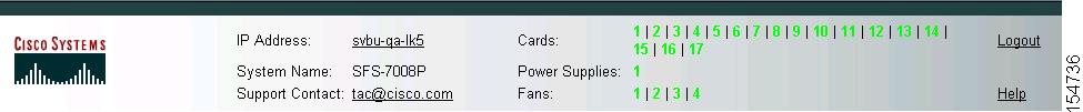
The System frame displays and updates the status of the cards, power supplies, and fans in your device. Each number in the Cards, Power Supplies, and Fans fields identifies a field-replaceable unit (FRU) in your device based on the slot number in which it resides. The color of the slot number indicates the status of the FRU. Figure 1-1 shows a system frame for an SFS 7008P Server Switch.
Figure 1-1 System Frame
Table 1-1 lists the colors in the display and explains what each color indicates.
Table 1-1 FRU Color Indicators
Color
|
Indication
|
green
|
Operational and administrative status of up.
|
gray
|
Administrative status of down.
|
red
|
Operational status of down.
|
•Launch a CLI session to the server switch by clicking the IP address in the IP Address field to open a Telnet window.
•Contact Cisco TAC from the Support Contact field by clicking the e-mail address and sending an e-mail message.
•Start the online help by clicking on Help.
Tree Frame
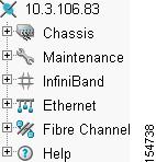
The Tree frame appears on the lower left of the Chassis Manager display and provides a navigation tree that groups the functional branches of your device under icons. Figure 1-2 displays the Tree frame on a Cisco SFS 3001 Server Switch.
Figure 1-2 Tree Frame
Note Figure 1-2 displays a tree frame for a user with unrestricted access. Restricted users may see fewer icons. For more information, see the "Understanding Access Privileges" section on page 2-9.
Table 1-2 describes the icons in the Tree frame.
Table 1-2 Tree Frame Icons
Icon
|
Description
|
Chassis ( ) )
|
The Chassis icon lets you view and configure hardware in your server switch. Access this icon to view the status of all field-replaceable units (FRUs) on your device.
|
Maintenance ( ) )
|
The Maintenance icon contains branches that let you perform basic administrative tasks on your server switch. Access this icon to configure Network Time Protocol (NTP) servers, assign a boot-config file, view the contents of the file system, and so on.
|
InfiniBand ( ) )
|
The InfiniBand icon provides subnet manager and I/O details. You can click the Subnet Manager branch of this icon to configure basic subnet manager properties.
|
Ethernet ( ) (select hardware platforms only) ) (select hardware platforms only)
|
The Ethernet icon lets you view and configure many aspects of IP traffic on your server switch.
|
Fibre Channel ( ) (select hardware platforms only) ) (select hardware platforms only)
|
The Fibre Channel icon shows your SRP host and Fibre Channel storage details and lets you configure global policies.
|
Help ( ) )
|
The Help icon takes you to online help and support resources.
|
Click a plus-sign icon ( ) to expand an icon and display the branches that you can configure. After you expand an icon, click a branch icon (
 ) to open the configuration options for that branch in the View frame.
Table 1-3 describes the configurable branches under the Chassis icon.
Table 1-3 Chassis Icon Branches
Branch
|
Description
|
Cards
|
Click this branch to display and configure controller, switch, and gateway cards.
|
Ports
|
Click this branch to display and configure all external InfiniBand, Ethernet, and Fibre Channel ports on your device.
|
Power Supplies (select hardware platforms only)
|
Click this branch to view the status of the power supplies on your device.
|
Fans (select hardware platforms only)
|
Click this branch to view the status of the fans on your device.
|
Sensors
|
Click this branch to view the status and readings on the temperature sensors on your device.
|
Backplane (select hardware platforms only)
|
Click this branch to view backplane details.
|
Management Ports
|
Expand the Management Ports icon to display the following branches:
•Serial displays the Serial Console port configuration.
•Ethernet displays the Ethernet Management port configuration.
•InfiniBand displays the InfiniBand Management port configuration.
|
Table 1-4 describes the configurable branches under the Maintenance icon.
Table 1-4 Maintenance Icon Branches
Branch
|
Description
|
System Information
|
Click this branch to view and configure the information that appears in the System frame.
|
System Global Settings
|
Click this branch to view the system global settings.
|
Time
|
Click this branch to configure the time and date on your server switch and to assign NTP servers to your device.
|
File Management
|
Click this branch to view, import, export, and install files in the file system on your device.
|
Boot Configuration
|
Click this branch to select a configuration for your server switch to use when it boots.
|
Backup Configuration
|
Click this branch to save your running configuration to a file.
|
Save Config
|
Click this branch to save the running configuration as the startup configuration. When your server switch reboots, it runs the updated configuration.
|
Reboot
|
Click this branch when you want to reload your server switch.
|
Services
|
Expand the Services icon to display the following branches:
•General
Displays the following system services and lets you configure them:
–DNS
–FTP
–Telnet
–Syslog
–RADIUS
–TACACS+
•HTTP
Displays HTTP properties and configuration options.
•Radius Servers
Displays the RADIUS server(s) that your device can use to authenticate user logins and lets you configure attributes of the server(s).
•Tacacs Servers
Displays the TACACS+ server(s) that your device can use to authenticate user logins and lets you configure attributes of the server(s).
•Authentication Failures
Lists CLI, SNMP, and HTTP authentication failures.
|
Diagnostics
|
Expand this branch to view server switch diagnostic data in the following branches:
•POST
•Fru Error
|
Table 1-5 describes the configurable branches under the InfiniBand icon.
Table 1-5 InfiniBand Icon Branches
Branch
|
Description
|
Subnet Managers
|
Click this branch to view and configure the subnet managers in your fabric.
|
Services
|
Click this branch to view the IB fabric services that have registered with the subnet manager.
|
Topology
|
Expand the Topology icon to display the following branches:
•Nodes
Click this branch to view the IB nodes in your IB fabric.
•Ports
Click this branch to view the IB ports in your IB fabric.
•Neighbors
Click this branch to display the interconnecting IB nodes and relevant ports in your IB fabric.
|
Device Management (select hardware platforms only)
|
Expand the Device Management icon to display the following branches:
•IOU
Click this branch to view the I/O unit on your server switch.
•IOCs
Click this branch to view the controller(s) on your device.
•IOC Services
Click this branch to view the IB features on your device.
|
Table 1-6 describes the configurable branches under the Ethernet icon.
Table 1-6 Ethernet Icon Branches
Branch
|
Description
|
Bridge Groups
|
Click this branch to view bridge groups on your server switch.
|
Bridge Subnet
|
Click this branch to view the subnets of bridge groups.
|
Bridge Forwarding
|
Click this branch to view the forwarding properties of bridge groups.
|
Redundancy Group
|
Click this branch to view redundancy groups.
|
Trunk Groups
|
Click this branch to view trunk groups on your server switch.
|
Table 1-7 describes the configurable branches under the Fibre Channel icon.
Table 1-7 Fibre Channel Icon Branches
Branch
|
Description
|
Global Policies
|
Click this branch to view and configure the default attributes of new IB-to-FC connections.
|
SRP Hosts
|
Click this branch to view and configure SRP hosts that serve as initiators for SAN fabrics.
|
Targets
|
Click this branch to view and configure Fibre Channel targets that connect to your server switch through FC gateways.
|
Logical Units
|
Click this branch to view and configure Fibre Channel LUNs that connect to your server switch through FC gateways.
|
ITs
|
Click this branch to view and configure attributes of initiator-target connections.
|
ITLs
|
Click this branch to view and configure attributes of initiator-target-LUN connections.
|
Global Statistics
|
Click this branch to view IB-to-FC traffic statistics.
|
Table 1-8 describes the configurable branches under the Help icon.
Table 1-8 Help Icon Branches
Branch
|
Description
|
Help Index
|
Click this branch to launch Chassis Manager online help.
|
Support
|
Click this branch to open the support website.
|
View Frame
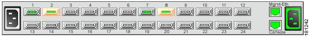
The View frame appears on the right of the interface. Input fields and device details appear in this frame. The contents of the View frame vary based on the branch that you click in the Tree frame. Figure 1-3 displays the graphic of the cable end, or service end, of the chassis that appears in the View frame when you first log in to the chassis manager.
Figure 1-3 View Frame on Logon
Ports 1 through 24 are InfiniBand ports.
•Ports with an operational status of up show with green pins.
•InfiniBand ports configured with double data rate (DDR) operational speed show with green pins and an orange surround.
•InfiniBand ports configured with single data rate (SDR) operational speed appear with green pins and a grey surround.
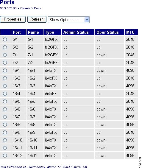
Figure 1-4 shows another View Frame example. You get this display when you expand Chassis in the tree frame and then click the Ports branch.
Figure 1-4 View Frame Example
Browser Requirements
Chassis Manager supports the following browsers:
•Microsoft Internet Explorer Version 6
•Netscape Navigator Version 6
•Mozilla Version 1.4
Platform Requirements
Chassis Manager runs on the following platforms:
•Windows
•Solaris
•Linux

 Feedback