Feedback
Table Of Contents
Understanding the Subnet Manager
Understanding Subnet Manager Routing Terms
Minimum Contention, Shortest Path, and Load Balancing Algorithm
Deterministic Source-Based Routing Algorithm
Configuring Your Network For Optimal Routing
Viewing Subnet Manager Properties
Configuring Subnet Manager Priority
Configuring a Subnet Manager Sweep Interval
Configuring a Subnet Manager Response Timeout
Configuring a Subnet Manager Master Poll Interval
Configuring Subnet Manager Master Poll Retries
Configuring the Maximum Number of Active Subnet Managers
Configuring the LID Mask Control
Configuring Switch Link HoQ Life
Configuring Wait Report Response
Configuring Subnet Agent MAD Queue Depth
Viewing Database Synchronization Details
Hexadecimal to Binary Conversions
Examples of Valid P_Key Values
Understanding how P_Keys are Saved
Configuring IPoIB Broadcast Multicast Groups
Viewing Multicast Group Details
Viewing Multicast Member Details
Viewing Switch Route Element Details
Configuring Subnet Manager Properties
Configuring Subnet Manager Priority
Configuring the Sweep Interval
Configuring the Master Poll Interval
Configuring the Number of Master Poll Retries
Configuring Switch Link HoQ Life
Configuring Wait Report Response
Configuring Subnet Agent MAD Queue Depth
Configuring Database Synchronization
Enabling Subnet Manager Database Synchronization
Configuring the Maximum Number of Backup Subnet Managers to Synchronize
Configuring the Cold Synchronization Timeout Value
Configuring the Cold Synchronization Limit Value
Configuring the Cold Synchronization Limit Period
Configuring the New Session Delay
Configuring the Resynchronization Interval
Viewing the Database Synchronization State
Adding Full Members to a Partition
Adding Available Members to a Partition
Adding Unavailable Members to a Partition
Adding Limited Members to a Partition
Adding Available Limited Members
Viewing Multicast Group Details
Viewing Multicast Group Members
Viewing Subnet Managers Information
Enabling InfiniBand Port Performance Management
Disabling Performance Management
Creating a Connection to Monitor
Viewing Connection Monitor Counters
Viewing Port Counters of Connections
Viewing Cumulative Port Counters
Configuring Port Monitoring Thresholds
Resetting Counters on All Ports on a Node
Resetting Counters on All Ports in a Connection
Resetting All Counters in a Subnet
Viewing Internal Server Switch Components and TCAs
Viewing Subnet Management Agents
Viewing Subnet Manager Node Details
Viewing Subnet Manager Switch Details
Viewing Subnet Manager Agent Switch Cap Details
Viewing Subnet Manager Agent Ports(1) Details
Viewing Subnet Manager Agent Ports(2) Details
Viewing Subnet Manager Multicast Details
Viewing Subnet Manager Agent Linear Forwarding Table Details
Viewing the Subnet Manager Agent Partition Details
InfiniBand Menu Tasks
This chapter describes the InfiniBand menu tasks for Element Manager and contains these sections:
•
Viewing Subnet Manager Properties
•
•
•
•
•
•
•
•
•
•
•
Note
Understanding InfiniBand
InfiniBand is a high speed, high density serial interconnect that increases CPU utilization, decreases latency, and eases the management problems of data centers. The term "InfiniBand" refers to the entire hardware, communication, and management infrastructure. Use of this technology increases the communication speed between the following:
•
•
•
InfiniBand combines high-speed hardware, specialized protocols, and Remote Data Memory Access (RDMA) techniques to increase CPU utilization and decrease latency. Operations of the InfiniBand Architecture are managed by the Subnet Manager.
InfiniBand Components
One or more of the following hardware components may be used to maximize your server network:
•
•
•
•
Protocols
InfiniBand requires a new set of protocols. All of the necessary protocol drivers are included with the Server Switch.
IPoIB
The IP over InfiniBand (IPoIB) link driver provides standardized IP encapsulation over InfiniBand fabrics. IPoIB can transparently use IP over InfiniBand technology, which is similar to the way that IP runs over Ethernet.
You can use the IPoIB driver to perform an address resolution and manage the multicast membership.
SDP
The Sockets Direct Protocol (SDP) is a transparent protocol used on InfiniBand networks to allow sockets-based applications to take advantage of the RDMA performance over an InfiniBand network. SDP reduces the amount of software running inside a process context. The zero-copy SDP support enables databases, application servers, and CPUs to operate more efficiently because the databases spend less time waiting for work, the application servers spend less time waiting for responses, and the CPUs have more cycles free for other work.
SRP
The SCSI RDMA Protocol (SRP) is an upper-layer storage protocol for InfiniBand that runs SCSI commands across RDMA-capable networks for InfiniBand hosts to communicate with Fibre Channel storage devices. This protocol allows InfiniBand hosts to natively send SCSI commands as if the storage was directly attached.
The SRP protocol uses an RDMA communication service that provides communication between pairs of consumers; it uses messages for control information and RDMA operations for data transfers.
The SRP protocol is used only if you have a Fibre Channel Gateway installed in your InfiniBand system.
uDAPL
The user Direct Access Programming Library (uDAPL) is a standardized user mode API that natively supports InfiniBand fabrics. uDAPL performs name-to-address translations, establishes connections, and transfers data reliably. The primary responsibilities of uDAPL are: connection management and low latency data transfer and completion
Architectural Elements
The following structures serve as foundational elements of InfiniBand architecture:
•
•
RDMA
InfiniBand uses RDMA technology. RDMA allows one computer to place information directly into the memory of another computer. RDMA allows user space applications to directly access hardware and zero-copy data movement.
A combination of hardware and software allows user space applications to read and write the memory of a remote system without kernel intervention or unnecessary data copies. This feature results in lower CPU utilization per I/O operation and more efficient use of machine resources because applications place most of the messaging burden upon InfiniBand's high-speed network hardware.
Queue Pairs
The queue pair (QP) is one of the primary architectural elements of InfiniBand. In InfiniBand, communication occurs between queue pairs, instead of between ports.
A queue pair is an addressable entity that consists of two work queues: a Send work queue and a Receive work queue. The Channel Adapter hardware arbitrates communication by multiplexing access to the send queue or demultiplexing messages on the receive queue.
Note
A work queue provides a consumer with the ability to queue up a set of instructions that are executed by the Channel Adapter. There are two types of work queues: Send work queues (outbound) and a receive work queues (inbound). Together these work queues create a queue pair.
A connection is made by linking a local queue pair to a remote queue pair. Applications do not share queue pairs; once you set them up, you can manage them at the application level without incurring the overhead of system calls.
Send and receive work queues have these characteristics:
•
•
•
•
Queue pairs have:
•
•
•
The queue pair is the mechanism by which you define quality of service, system protection, error detection and response, and allowable services.
Each queue pair is independently configured for a particular type of service. These service types provide different levels of service and different error-recovery characteristics as follows:
•
•
•
•
Once the fabric connections are discovered, queue pairs and protection domains are established, the type and quality of service are defined for each queue pair, and the fabric operates reliably and securely at full QoS without impacting system hardware or software resources.
Understanding the Subnet Manager
The Subnet Manager configures and maintains fabric operations. There can be multiple Subnet Managers, but only one master. The Subnet Manager is the central repository of all information that is required to set up and bring up the InfiniBand fabric.
The master Subnet Manager does the following:
•
•
•
–
–
–
•
•
•
Subnet Management Agents
Subnet Manager Agents are part of the Subnet Manager. A Subnet Manager Agent is provided with each node and process packets from the Subnet Manager.
If a Subnet Manager is elected master, all of its components, including Subnet Agent, are implicitly elected master. If a Subnet Manager ceases to be the master, all of its components cease responding to messages from clients.
Subnet Manager Hot Standby
The master and slave Subnet Managers can be synchronized so that the information in the master is carried over to the slave if a fail-over occurs. See the "Enabling Subnet Manager Database Synchronization" section to configure the hot-standby Subnet Manager.
The hot standby/database synchronization feature is used to synchronize the databases between Subnet Managers running on separate chassis.
The Subnet Manager maintains a database in the volatile memory of the master Subnet Manager. Database synchronization is accomplished in two stages:
•
•
A standby Subnet Manager can become the master in any of these situations:
•
•
•
The following occurs in the event of a failure:
•
•
•
•
•
Subnet Manager Routing
There are two different concepts associated with InfiniBand routing:
•
•
Note
Internal switch routing can be configured to provide the highest performance in passing traffic and to minimize the threat of congestion within the switch.
The routing process is as follows:
Step 1
Step 2
Step 3
Step 4
Step 5
Multiple Paths
The Subnet Manager allows you to define the Local Identifier Mask Control (LMC) value per subnet. The default value of the LMC is 0. By default, only one Local Identifier (LID) is assigned to each host port.
Once the LMC value has been assigned, the Subnet Manager will route different paths for each LID associated with the same host port. The result of these paths is based on the applied routing algorithm.
Understanding Subnet Manager Routing Terms
The following terms are important to understand before distinguishing the various types of algorithms that the Subnet Manager uses for routing:
•
–
–
•
Minimum Contention, Shortest Path, and Load Balancing Algorithm
The Minimum Contention, Shortest Path and Load Balancing algorithm is used by default to route between the switch elements and between the internal InfiniBand switch chips within each switch element.
The following process shows how the algorithm makes the calculation:
Step 1
Step 2
a.
b.
c.
Deterministic Source-Based Routing Algorithm
The Deterministic Source Based Routing algorithm is used in some high-performance computing environments where the requirements may need to be more stringently defined. An administrator can identify the exact route that a given port and LID takes for traversing through the network.
Currently, only the internal routing for the Cisco SFS 7008 (a 96-port switch) supports this routing scheme. See the Cisco SFS 7008 Hardware Guide, or contact technical support for more information.
Configuring Your Network For Optimal Routing
For optimal routing, we recommend that you follow these steps:
•
•
We recommend that InfiniBand switch elements be connected so that all paths between any pair of switch elements are the same distance (same number of hops), if possible. This process enables you to obtain the optimal paths using the default tolerance of 0. If the paths have different lengths, then the tolerance value will need to be determined.
The Subnet Manager Routing Algorithm selects the first best path that it finds. If multiple paths with the same properties are available, then the first of these paths found is the one that is selected. It is possible to set up the cabling between switch elements to force the algorithm to prioritize certain paths. Depending on the network requirements, the prioritized paths can either be concentrated on a particular switch element or spread across multiple switch elements to improve fault tolerance.
Viewing Subnet Manager Properties
To view Subnet Manager properties, follow these steps:
Step 1
The Subnet Manager window opens.
Step 2
A table of Subnet Manager properties appears under the General tab. Table 8-1 describes the fields.
Configuring Subnet Manager Priority
To configure Subnet Manager priority, follow these steps:
Step 1
The Subnet Manager window opens.
Step 2
A table of Subnet Manager properties appears.
Step 3
Step 4
Configuring a Subnet Manager Sweep Interval
To configure a Subnet Manager sweep interval, follow these steps:
Step 1
The Subnet Manager window opens.
Step 2
A table of Subnet Manager properties appears.
Step 3
Step 4
Configuring a Subnet Manager Response Timeout
To configure Subnet Manager response timeout, follow these steps:
Step 1
The Subnet Manager window opens.
Step 2
A table of Subnet Manager properties appears.
Step 3
Step 4
Configuring a Subnet Manager Master Poll Interval
To configure the interval at which the switch polls the master switch, follow these steps:
Step 1
The Subnet Manager window opens.
Step 2
A table of Subnet Manager properties appears.
Step 3
Step 4
Configuring Subnet Manager Master Poll Retries
To configure the number of Subnet Manager master poll retries, follow these steps:
Step 1
The Subnet Manager window opens.
Step 2
A table of Subnet Manager properties appears.
Step 3
Step 4
Configuring the Maximum Number of Active Subnet Managers
To configure the maximum number of active Subnet Managers on the InfiniBand network, follow these steps:
Step 1
The Subnet Manager window opens.
Step 2
A table of Subnet Manager properties appears.
Step 3
Step 4
Configuring the LID Mask Control
To configure the local ID mask control, follow these steps:
Step 1
The Subnet Manager window opens.
Step 2
A table of Subnet Manager properties appears.
Step 3
Step 4
Configuring Switch Lifetime
To configure the switch lifetime, follow these steps:
Step 1
The Subnet Manager window opens.
Step 2
A table of Subnet Manager properties appears.
Step 3
Step 4
Configuring Switch Link HoQ Life
To configure the switch link head of queue (HoQ) life, follow these steps:
Step 1
The Subnet Manager window opens.
Step 2
A table of Subnet Manager properties appears.
Step 3
Step 4
Configuring CA Link HoQ Life
To configure the collision allowance (CA) link for head of queue (HoQ) life, follow these steps:
Step 1
The Subnet Manager window opens.
Step 2
A table of Subnet Manager properties appears.
Step 3
Step 4
Configuring Maximum Hop Count
We recommend that InfiniBand switch elements be connected so that all paths between any pair of switch elements are the same distance (same number of hops), if possible. To configure the maximum hop count, follow these steps:
Step 1
The Subnet Manager window opens.
Step 2
A table of Subnet Manager properties appears.
Step 3
Step 4
Configuring MAD Retries
To configure MAD retries, follow these steps:
Step 1
The Subnet Manager window opens.
Step 2
A table of Subnet Manager properties appears.
Step 3
Step 4
Configuring Node Timeout
To configure the node timeout, follow these steps:
Step 1
The Subnet Manager window opens.
Step 2
A table of Subnet Manager properties appears.
Step 3
Step 4
Configuring Wait Report Response
To configure the wait report response, follow these steps:
Step 1
The Subnet Manager window opens.
Step 2
A table of Subnet Manager properties appears.
Step 3
Step 4
Configuring Subnet Agent MAD Queue Depth
To configure Subnet Agent MAD queue depth, follow these steps:
Step 1
The Subnet Manager window opens.
Step 2
A table of Subnet Manager properties appears.
Step 3
Step 4
Viewing Database Synchronization Details
Element Manager provides multiple screens that you can use to configure database synchronization. Configuration details and field descriptions are in the "Configuring Database Synchronization" section.
Step 1
The Subnet Manager window opens.
Step 2
Details appear in the table below the tab.
Note
Understanding Partitions
A partition defines a set of InfiniBand nodes that are permitted to communicate with one another. Partitions do the following:
•
•
•
Note
How Partitions Work
A partition defines a set of InfiniBand nodes that are permitted to communicate with one another. Each node may be part of multiple partitions so that a system administrator can define overlapping partitions as the situation requires. Normal data packets carry a 16-bit P_Key, or partition key, that defines a unique partition. The Subnet Manager configures each node's channel adapter with its set of P_Keys. When a packet arrives at a node, the channel adapter checks that the packet's P_Key is valid based on the Subnet Manager's configuration. Packets with invalid P_Keys are discarded. P_Key validation prevents a server from communicating with another server outside of its partition.
InfiniBand partitions are comparable to hardware-enforced security features of conventional I/O networking technologies, such as Ethernet VLANs and Fibre-Channel zones.
Partition Members
Without members, a partition does not have meaning to the system. Ports are added to the partition, and become members of that partition. Each port may be part of multiple partitions so that you can define overlapping partitions as the situation requires.
At the time a port member is added to the partition, you must decide whether that particular port will have full or limited membership.
Membership Types
A partition contains a group of members, but different types of members can exist within a single partition. Partition memberships allows even further control because it defines communication within the members of that group, not just outside of it.
There are two types of partition memberships: full membership and limited membership. A full-membership partition member can communicate with all other partition members including other full members and limited members. A limited-membership partition member cannot communicate with other limited-membership partition members. However, a limited partition member can communicate with a full member.
About the Default Partition
The Subnet Manager automatically configures a default partition, which is always p_key ff:ff.
The default partition controls all connected ports, and by default, everything is a full member of the default partition. The default p_key cannot be altered or deleted as it is the controlling mechanism that manages the configuration of all the partitions.
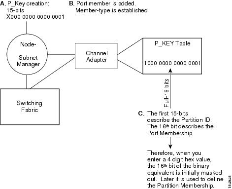
Selecting a P_Key Value
For a list of acceptable P_Key values, see Table 8-3.
Upon creation, the p_key value (see Figure 8-1) is technically a 15-bit number. However, after the p_key is created and the port(s) membership type has been established, the entire value becomes 16 bits. The most significant bit (MSB) displays the type of membership (0 = Limited member, 1 = Full member).
When assigning a p_key value, you need to choose four hexadecimal numbers. However, because of the way that the 16th bit is used, only certain numbers can be used for the left-most variable (the MSB). For example, do not create two p_keys:
Do not create two p_keys because they will be viewed as the same number by the system. For example, if you created 0 #:# # and 8#:# #, the system would view them as the same number.
Figure 8-1 Partition Keys
Hexadecimal to Binary Conversions
Table 8-2 is provided to assist in the creation of P_keys. When creating the partition p_key, enter a hexadecimal value that is the equivalent of 16 bits in binary. For example, enter 80:00 (hex) to be 10000000000000000 (binary). The default partition (which cannot be altered) is 7f:ff.
Table 8-2 Binary Conversions
0
0000
1
0001
2
0010
3
0011
4
0100
5
0101
6
0110
7
0111
8
1000
9
1001
A
1010
B
1011
C
1100
D
1101
E
1110
F
1111
Examples of Valid P_Key Values
You can choose your own p_key values, or you can choose your values from the list in Table 8-3.
Table 8-3 Valid P_Key Numbers
00:01
00:11
00:02
00:12
00:03
00:13
00:04
00:14
00:05
00:15
00:06
00:16
00:07
00:17
00:08
00:18
00:09
00:19
00:10
00:20
Understanding how P_Keys are Saved
Partition information is saved by the master Subnet Manager. If db-sync is enabled, the master Subnet Manager synchronizes P_key information to standby Subnet Managers (currently, only one standby manager is allowed). A synchronized standby retains the information from the master.
If you configure only one InfiniBand switch, it is automatically the master, and the partition configuration is saved persistently on the switch. See the "Enabling Subnet Manager Database Synchronization" section for details.
Viewing Partition Details
To view the attributes of the partitions on your Server Switch, follow these steps:
Step 1
The Subnet Manager window opens.
Step 2
Details appear in the table below the tab. Table 8-4 describes the fields in the table.
Note
Configuring Multicast Groups
To configure multicast groups, follow these steps:
Step 1
The Subnet Manager window opens.
Step 2
Step 3
Step 4
Step 5
Step 6
Step 7
Step 8
Step 9
Step 10
Step 11
Step 12
Step 13
Note
Configuring IPoIB Broadcast Multicast Groups
To configure IPoIB broadcast multicast groups, follow these steps:
Step 1
The Subnet Manager window opens.
Expand a subnet.
Step 2
Step 3
Step 4
Step 5
Step 6
Step 7
Step 8
Step 9
Step 10
Step 11
Step 12
Note
Viewing Multicast Group Details
To view the attributes of the multicast groups on your Server Switch, follow these steps:
Step 1
The Subnet Manager window opens.
Expand a subnet.
Step 2
You see the multicast information in the right pane. Table 8-5 describes the fields.
Note
Viewing Multicast Member Details
To view the details of the multicast members on your Server Switch, follow these steps:
Step 1
The Subnet Manager window opens.
Step 2
Details appear in the table below the tab. Table 8-5 describes the fields in the table.
Note
Viewing InfiniBand Services
Subnet services provide your InfiniBand fabric with various features, such as the ability to run particular protocols. To view the subnet services on your InfiniBand fabric, follow these steps:
Step 1
The Subnet Manager window opens.
Step 2
Details appear in the table below the tab. Table 8-7 describes the fields in the Subnet Managers table.
Viewing Switch Route Details
Switch routes represent the complete path that traffic takes through the InfiniBand fabric from the source LID to the destination LID. To view the details of the switch routes on your Server Switch, follow these steps:
Step 1
The Subnet Manager window opens.
Step 2
Details appear in the table below the tab. Table 8-8 describes the fields in the table.
Note
Viewing Switch Route Element Details
To view the details of the switch element routes on your Server Switch, follow these steps:
Step 1
The Subnet Manager window opens.
Step 2
Details appear in the table below the tab. Table 8-9 describes the fields in the table.
Note
Adding a Subnet Manager
To add a Subnet Manager to your Server Switch, follow these steps:
Step 1
The Subnet Management window opens.
Step 2
The Subnet Managers display appears in the right pane of the window.
Step 3
The Add Subnet Manager window opens.
Step 4
Step 5
Step 6
Step 7
Step 8
The new Subnet Manager appears in the Summary table in the Subnet Managers display.
Removing a Subnet Manager
To remove a Subnet Manager from your Server Switch, follow these steps:
Step 1
The Subnet Management window opens.
Step 2
The Subnet Managers display appears in the right pane of the window.
Step 3
Step 4
The entry disappears from the display and the Server Switch configuration.
Configuring Subnet Manager Properties
The Subnet Managers navigation menu provides tuning for a number of system-wide attributes. The sections that follow explain each attribute and describe how to configure it.
Configuring Subnet Manager Priority
Every Subnet Manager in the InfiniBand network carries a priority value, and at any given time the Subnet Manager with the highest integer value priority becomes the master Subnet Manager. To configure the Subnet Manager priority on your Server Switch, follow these steps:
Step 1
The Subnet Management window opens.
Step 2
Each Subnet Manager appears in the navigation pane with a Subnet Manager icon (
).
Step 3
The integer value 1 has the highest the priority.
Step 4
Configuring the Sweep Interval
The sweep interval specifies how frequently the Subnet Manager queries the InfiniBand fabric for network changes. To configure the sweep interval on your Server Switch, follow these steps:
Step 1
The Subnet Management window opens.
Step 2
Each Subnet Manager appears in the navigation pane with a Subnet Manager icon (
).
Step 3
This interval represents the number of seconds between sweeps.
Step 4
Configuring Response Timeout
The response timeout of a Subnet Manager specifies the maximum amount of time that the Subnet Manager waits for a response after it sends a packet to a port. If the Subnet Manager does not receive a response in the response-time interval, the Subnet Manager identifies the port as unresponsive. To configure the response timeout, follow these steps:
Step 1
The Subnet Management window opens.
Step 2
Each Subnet Manager appears in the navigation pane with a Subnet Manager icon (
).
Step 3
The Subnet Manager measures the response timeout in milliseconds.
Step 4
Configuring the Master Poll Interval
The master poll interval determines the interval at which the slave Subnet Manager polls the master to see if the master still runs. To configure the master poll interval, follow these steps:
Step 1
The Subnet Management window opens.
Step 2
Each Subnet Manager appears in the navigation pane with a Subnet Manager icon (
).
Step 3
The value represents the interval, in seconds.
Step 4
Configuring the Number of Master Poll Retries
Master poll retries specifies the number of unanswered polls that cause a slave to identify a master as dead. To specify this value, follow these steps:
Step 1
The Subnet Management window opens.
Step 2
Each Subnet Manager appears in the navigation pane with a Subnet Manager icon (
).
Step 3
Step 4
Configuring the Maximum Number of Active Standby Subnet Managers that the Master Subnet Manager Supports
Note
To configure the maximum number of active standby Subnet Managers that the master Subnet Manager supports, follow these steps:
Step 1
The Subnet Management window opens.
Step 2
Each Subnet Manager appears in the navigation pane with a Subnet Manager icon (
).
Step 3
Step 4
Configuring LID Mask Control
Local ID mask control assigns the number of path bits present in the base LID to each channel adapter port. Increasing the LMC value increases the number of LIDs assigned to each port to increase the number of potential paths to reach each port. To configure LID mask control, follow these steps:
Step 1
The Subnet Management window opens.
Step 2
Each Subnet Manager appears in the navigation pane with a Subnet Manager icon (
).
Step 3
Step 4
Configuring Switch Lifetime
Switch lifetime is one parameter that governs the transmitter packet discard policy of switches in the subnet. It determines the lifetime of packets in a switch from the point of ingress to egress. If this parameter is set to 20 or greater, then switch lifetimes are infinite (default). See InfiniBand Architecture Release 1.2, Volume 1 for more information.
Step 1
The Subnet Management window opens.
Step 2
Each Subnet Manager appears in the navigation pane with a Subnet Manager icon (
).
Step 3
Step 4
Configuring Switch Link HoQ Life
Switch link head of queue life determines how long an InfiniBand packet lives at the head of a switch port VL queue before it is discarded. If this parameter is set to 20 or greater, then HoQ lifetimes are infinite (default). See InfiniBand Architecture Release 1.2, Volume 1 for more information.
Step 1
The Subnet Management window opens.
Step 2
Step 3
Step 4
Configuring Maximum Hop Count
To configure the maximum number of hops for an InfiniBand Subnet Manager, follow these steps:
Step 1
The Subnet Manager window opens.
Step 2
Each Subnet Manager appears in the navigation pane with a Subnet Manager icon (
).
Step 3
Step 4
Configuring MAD Retries
To configure MAD retries, follow these steps:
Step 1
The Subnet Manager window opens.
Step 2
A table of Subnet Manager properties appears.
Step 3
Step 4
Configuring Node Timeout
To configure the node timeout, follow these steps:
Step 1
The Subnet Manager window opens.
Step 2
A table of Subnet Manager properties appears.
Step 3
Step 4
Configuring Wait Report Response
To configure the wait report response, follow these steps:
Step 1
The Subnet Manager window opens.
Step 2
A table of Subnet Manager properties appears.
Step 3
Step 4
Configuring Subnet Agent MAD Queue Depth
To configure the Subnet Agent MAD queue depth, follow these steps:
Step 1
The Subnet Manager window opens.
Step 2
A table of Subnet Manager properties appears.
Step 3
Step 4
Configuring Database Synchronization
The database synchronization feature propagates information from the database of the master Subnet Manager to the standby Subnet Managers. The sections that follow describe how to configure this feature.
Enabling Subnet Manager Database Synchronization
If you are configuring more than one InfiniBand chassis in your fabric, it is likely that you will want to enable database synchronization of the Subnet Managers.
Note
To enable Subnet Manager database synchronization to update standby Subnet Managers with information from the master Subnet Manager, follow these steps:
Step 1
The Subnet Management window opens.
Step 2
Each Subnet Manager appears in the navigation pane with a Subnet Manager icon (
).
Step 3
Step 4
Step 5
Configuring the Maximum Number of Backup Subnet Managers to Synchronize
To configure the maximum number of backup Subnet Managers that will synchronize with the master Subnet Manager, follow these steps:
Step 1
The Subnet Management window opens.
Step 2
Each Subnet Manager appears in the navigation pane with a Subnet Manager icon (
).
Step 3
Step 4
Step 5
Configuring a Session Timeout
To configure the session timeout interval, in seconds, during which a synchronization session status MAD packet must arrive at the master Subnet Manager to maintain synchronization, follow these steps:
Step 1
The Subnet Management window opens.
Step 2
Each Subnet Manager appears in the navigation pane with a Subnet Manager icon (
).
Step 3
Step 4
This value determines the timeout duration, in seconds.
Step 5
Configuring the Poll Interval
To configure the interval, in seconds, at which the master Subnet Manager polls an active slave Subnet Manager to verify synchronization, follow these steps:
Step 1
Step 2
Step 3
Each Subnet Manager appears in the navigation pane with a Subnet Manager icon (
).
Step 4
Step 5
This value sets the poll interval, in seconds.
Step 6
Configuring the Cold Synchronization Timeout Value
To configure the amount of time, in seconds, that a cold synchronization tries to initiate before it times out, follow these steps:
Step 1
The Subnet Management window opens.
Step 2
Each Subnet Manager appears in the navigation pane with a Subnet Manager icon (
).
Step 3
Step 4
This value sets the timeout interval, in seconds.
Step 5
Configuring the Cold Synchronization Limit Value
To configure the maximum number of cold synchronizations to perform during a given cold synchronization period, follow these steps:
Step 1
The Subnet Management window opens.
Step 2
Each Subnet Manager appears in the navigation pane with a Subnet Manager icon (
).
Step 3
Step 4
This value sets the maximum number of synchronizations that can occur during the synchronization period ("Configuring the Cold Synchronization Limit Period" section).
Step 5
Configuring the Cold Synchronization Limit Period
To specify the length of the interval during which cold synchronizations may occur, follow these steps:
Step 1
The Subnet Management window opens.
Step 2
Each Subnet Manager appears in the navigation pane with a Subnet Manager icon (
).
Step 3
Step 4
This value sets the length of the interval during which cold synchronizations may occur.
Step 5
Configuring the New Session Delay
To configure the amount of time that the master Subnet Manager waits before it attempts to initiate a synchronization session with a new Subnet Manager, follow these steps:
Step 1
The Subnet Management window opens.
Step 2
Each Subnet Manager appears in the navigation pane with a Subnet Manager icon (
).
Step 3
Step 4
This value determines the amount of time, in seconds, that the master Subnet Manager waits before it attempts to initiate a synchronization session with a new Subnet Manager.
Step 5
Configuring the Resynchronization Interval
To specify the interval at which the master Subnet Manager sends a resynchronization request to all active synchronization sessions, follow these steps:
Step 1
The Subnet Management window opens.
Step 2
Each Subnet Manager appears in the navigation pane with a Subnet Manager icon (
).
Step 3
Step 4
This value specifies the interval, in seconds, at which the master Subnet Manager sends a resynchronization request to all active synchronization sessions.
Step 5
Viewing the Database Synchronization State
To view the database synchronization state and verify that the master Subnet Manager and slave Subnet Manager(s) are synchronized, follow these steps:
Step 1
The Subnet Management window opens. Each Subnet Manager appears in the navigation pane with a Subnet Manager icon (
).
Step 2
Step 3
Step 4
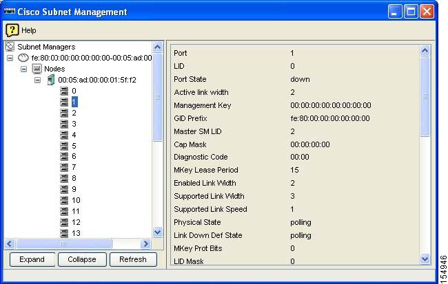
Viewing Nodes
To view Subnet Manager node information, follow these steps:
Step 1
The Subnet Management window opens. Each Subnet Manager appears in the navigation pane with a Subnet Manager icon (
).
Step 2
Step 3
The Nodes in Subnet tab displays the Node GUID, Type, Description, Number of Ports, System Image GUID, and the Vendor ID information.
Step 4
Figure 8-2 Individual Node Information
Viewing Partitions
To view the partitions on your InfiniBand network, follow these steps:
Step 1
The Subnet Management window opens.
Step 2
The navigation menu expands.
Step 3
) branch.
The partitions summary appears in the right pane. Table 8-10 describes the fields in this display.
Creating a Partition
To create an InfiniBand partition, follow these steps:
Step 1
The Subnet Management window opens.
Step 2
Step 3
) branch.
Step 4
The Add Partition window opens.
Step 5
Removing a Partition
To delete a partition, follow these steps:
Step 1
The Subnet Management window opens.
Step 2
Step 3
) branch.
Step 4
Viewing Partition Details
To view partition details, follow these steps:
Step 1
The Subnet Management window opens.
Step 2
Step 3
) branch to display all partitions.
Step 4
The members (full and limited) of the partition appear in the display.
Note
Adding Full Members to a Partition
Full members of a partition can communicate to other full members and to limited members.
Adding Available Members to a Partition
To add available members to a partition, follow these steps:
Step 1
The Subnet Management window opens.
Step 2
Step 3
) branch to display all partitions in the navigation menu.
Step 4
The members (full and limited) of the partition appear in the display.
Step 5
Adding Unavailable Members to a Partition
To add unavailable members ( members that do not appear in the Available Members pool) to a partition, follow these steps:
Step 1
The Subnet Management window opens.
Step 2
Step 3
) branch to display all partitions in the navigation menu.
Step 4
The members (full and limited) of the partition appear in the display.
Step 5
The Add Other Partition Member window opens.
Step 6
Step 7
Step 8
Adding Limited Members to a Partition
Limited members of a partition can communicate with full members of the partition but not with other limited members.
Adding Available Limited Members
To add available limited members to a partition, follow these steps:
Step 1
The Subnet Management window opens.
Step 2
The navigation menu expands.
Step 3
) branch to display all partitions in the navigation menu.
Step 4
The members (full and limited) of the partition appear in the display.
Step 5
Adding Unavailable Members
To add an unavailable member (member does not appear in the Available Members pool) to a partition, follow these steps:
Step 1
The Subnet Management window opens.
Step 2
Step 3
) branch to display all partitions in the navigation menu.
Step 4
The members (full and limited) of the partition appear in the display.
Step 5
The Add Other Partition Member window opens.
Step 6
Step 7
Step 8
Viewing Multicast Groups
To view the multicast groups on your InfiniBand network, follow these steps:
Step 1
The Subnet Management window opens.
Step 2
The navigation menu expands.
Step 3
) branch.
The multicast groups summary appears in the right pane. Table 8-11 describes the fields in this display.
Viewing Multicast Group Details
To view multicast group details, follow these steps:
Step 1
The Subnet Management window opens.
Step 2
The navigation menu expands.
Step 3
) branch to display all groups in the navigation menu.
Step 4
Multicast group details appear in the display. Table 8-12 describes the fields in this display.
Viewing Multicast Group Members
Step 1
The Subnet Management window opens.
Step 2
The navigation menu expands.
Step 3
) branch to display all groups in the navigation menu.
Step 4
Multicast group members appear in the display. Table 8-13 describes the fields in this display.
Viewing InfiniBand Services
To view the InfiniBand services that run on your Server Switch, follow these steps:
Step 1
The Subnet Management window opens.
Step 2
Step 3
) branch.
Details of InfiniBand services appear in the right pane.
Table 8-14 describes the fields in the Summary section of the display.
Table 8-15 describes the fields in the Services Details section of the display.
Viewing InfiniBand Routes
To view the route between a pair of LIDs in the InfiniBand fabric. follow these steps:
Step 1
The Subnet Management window opens.
Step 2
Step 3
) branch.
InfiniBand routes fields appear in the right pane.
Step 4
Step 5
Step 6
Step 7
Table 8-16 lists the fields under the Switch Route tab.
Table 8-16 Switch Route Field Descriptions
Node GUID
Global unique ID of the node.
In Port
Port of ingress.
Out Port
Port of egress.
Step 8
Table 8-17 displays the fields under the Switch Element Route tab.
Table 8-17 Switch Element Route Field Descriptions
Chassis GUID
Global unique ID of the node.
In Port
Port of ingress.
Out Port
Port of egress.
Viewing Subnet Managers Information
To view information on other Subnet Managers in the network, follow these steps:
Step 1
The Subnet Management window opens.
Step 2
The navigation menu expands.
Step 3
The Port GUID, Priority, and Subnet Manager state information appears in the right pane.
Table 8-18 describes the fields in the Details pane.
Table 8-18 Subnet Managers Information Details Pane
Note
Viewing Event Subscriptions
To view the Subnet Management event subscriptions information, follow these steps:
Step 1
The Subnet Management window opens.
Step 2
The navigation menu expands.
Step 3
The LID, Node GUID, and Port Number information appears in the right pane.
Table 8-19 describes the fields under Subnet Management Event Subscriptions Details.
Enabling InfiniBand Port Performance Management
Use performance management to view InfiniBand port counters, test connectivity between InfiniBand ports, and monitor InfiniBand ports for errors. To enable InfiniBand-port performance management, follow these steps:
Step 1
The Performance Management window opens.
Step 2
The Port Counter Configuration display appears in the right pane of the window.
Step 3
Disabling Performance Management
To disable performance management, follow these steps:
Step 1
The Performance Management window opens.
Step 2
The Port Counter Configuration display appears in the right pane of the window.
Step 3
Monitoring Connections
To monitor connections, you complete tasks such as:
•
•
•
•
Creating a Connection to Monitor
To create a connection to monitor, follow these steps:
Step 1
The Performance Management window opens.
Step 2
Step 3
The Monitored Connection tab appears in the right pane of the window.
Step 4
The Add Connection window opens.
Step 5
Note
Step 6
Step 7
Note
Step 8
The connection entry appears under the Monitored Connections tab.
Viewing Monitored Connections
These instructions assume that you have already defined connections to monitor. To view monitored connections, follow these steps:
Step 1
The Performance Management window opens.
Step 2
The navigation tree expands.
Step 3
The Monitored Connection tab appears in the right pane of the window. Table 8-20 describes the fields in this display.
Table 8-20 Monitored Connections Field Descriptions
Subnet Prefix
Subnet prefix of the monitored connection.
Source LID
16-bit source Local ID of the connection.
Destination LID
16-bit destination Local ID of the connection.
Error Status
Displays unknown, exceeded, or notExceeded to indicate if the error value has exceeded the threshold that you configured. To configure thresholds, see the "Configuring Port Monitoring Thresholds" section.
Util Status
Displays unknown, exceeded, or notExceeded to indicate if the utilization value has exceeded the threshold that you configured. To configure thresholds, see the "Configuring Port Monitoring Thresholds" section.
Viewing Connection Counters
Each hop in the display is a port on a node. When connections move through nodes, they enter the node in one hop (GUID A, port a), and exit in another hop (GUID A, port b). Though the GUIDs of subsequent hops may match, the ports do not match. To view connection counters, follow these steps:
Step 1
The Performance Management window opens.
Step 2
Step 3
Step 4
Step 5
Table 8-21 describes the fields in the display.
Viewing Connection Monitor Counters
To view connection monitor counters, follow these steps:
Step 1
The Performance Management window opens.
Step 2
Step 3
Step 4
Step 5
Table 8-22 describes the fields in the display.
Testing Connections
To test connections, follow these steps:
Step 1
The Performance Management window opens.
Step 2
Step 3
Step 4
Step 5
Step 6
Viewing Port Counters of Connections
To view port counters, follow these steps:
Step 1
The Performance Management window opens.
Step 2
Step 3
Step 4
Step 5
Table 8-23 describes the fields in this display.
Viewing Port Counters
To view port counters, follow these steps:
Step 1
The Performance Management window opens.
Step 2
Step 3
Step 4
•
•
Counters appear for that individual port. Table 8-24 describes the fields in the port counters display.
Viewing Cumulative Port Counters
To view cumulative port counters, follow these steps:
Step 1
The Performance Management window opens.
Step 2
Step 3
Step 4
Step 5
Step 6
Table 8-25 describes the fields in the display.
Enabling Port Monitoring
To enable port monitoring, follow these steps:
Step 1
The Performance Management window opens.
Step 2
Step 3
Step 4
Step 5
Note
Step 6
Configuring Port Monitoring
Step 1
The Performance Management window opens.
Step 2
The navigation tree expands.
Step 3
Step 4
Step 5
Step 6
Configuring Port Monitoring Thresholds
To configure port monitoring thresholds, follow these steps:
Step 1
The Performance Management window opens.
Step 2
The navigation tree expands.
Step 3
Step 4
Step 5
Step 6
Resetting Counters
You can reset counters for the following:
•
•
•
Resetting Counters on a Hop
To reset counters on a hop, follow these steps:
Step 1
The Performance Management window opens.
Step 2
Step 3
Step 4
Step 5
Resetting Counters on All Ports on a Node
To reset counters on all ports of a node, follow these steps:
Step 1
The Performance Management window opens.
Step 2
Step 3
Step 4
Step 5
Resetting Counters on All Ports in a Connection
To reset counters on all ports in a connection, follow these steps:
Step 1
The Performance Management window opens.
Step 2
Step 3
Step 4
Resetting All Counters in a Subnet
To reset all counters in a subnet, follow these steps:
Step 1
The Performance Management window opens.
Step 2
Step 3
Launching the Topology View
To launch the topology view, follow these steps:
Step 1
The Specify Topspin Devices dialog box opens.
Step 2
Step 3
The InfiniBand Topology appears.
Note
Table 8-26 InfiniBand Topology Navigation Icons

The Refresh icon refreshes the topology display.

The Layout icon evenly arranges the switch and HCA icons.

The Zoom In icon enlarges the display.

The Zoom Out icon condenses the display.

The Fit to Screen icon zooms in or out to fit the topology in the window.

The Specify Topspin Devices icon opens the Specify Cisco Devices dialog box to add Server Switches to the display.

The Legend icon displays the different colors that represent different types of links.

The Subnet Details icon displays subnet details. For more information, see the "Viewing Subnet Details" section.

The Help icon launches the online help.
Viewing Internal Server Switch Components and TCAs
To view the internal server switch components and target channel adapters (TCAs) inside a server switch, follow these steps:
Step 1
The Specify Topspin Devices dialog box opens.
Step 2
Step 3
The InfiniBand Topology window appears.
Step 4
The Internal InfiniBand Topology window opens.
Note
Table 8-27 Internal InfiniBand Topology Navigation Icons

The Layout icon evenly arranges the switch and HCA icons.

The Zoom In icon enlarges the display.

The Zoom Out icon condenses the display.

The Fit to Screen icon zooms in or out to fit the topology in the window.

The Layout icon evenly arranges the switch and HCA icons.

The Subnet Management Agents icon displays Subnet Manager agent details. For information, see the "Viewing Subnet Management Agents" section.

The Help icon launches the online help.
Viewing Subnet Details
You can view any of the following subnet details:
Viewing Nodes
To view the nodes in the topology view, follow these steps:
Step 1
The Specify Topspin Devices dialog box opens.
Step 2
Step 3
The InfiniBand Topology window appears.
Step 4
The InfiniBand Subnet Details window opens.
Step 5
Table 8-28 describes the fields in this tab.
Viewing Ports
To view the ports in the topology view, follow these steps:
Step 1
The Specify Topspin Devices dialog box opens.
Step 2
Step 3
The InfiniBand Topology window appears.
Step 4
The InfiniBand Subnet Details window opens.
Step 5
Table 8-29 describes the fields in this tab.
Viewing Switches
To view the switches in the topology view, follow these steps:
Step 1
The Specify Topspin Devices dialog box opens.
Step 2
Step 3
The InfiniBand Topology window appears.
Step 4
The InfiniBand Subnet Details window opens.
Step 5
Table 8-30 describes the fields in this tab.
Viewing Neighboring Ports
To view neighboring ports in the topology view, follow these steps:
Step 1
The Specify Topspin Devices dialog box opens.
Step 2
Step 3
The InfiniBand Topology window appears.
Step 4
The InfiniBand Subnet Details window opens.
Step 5
Table 8-31 describes the fields in this tab.
Viewing Subnet Management Agents
You can view any of the following Subnet Manager Agent details:
•
•
•
•
•
•
•
•
Viewing Subnet Manager Node Details
To view Subnet Manager Agent node details, follow these steps:
Step 1
The Specify Topspin Devices dialog box opens.
Step 2
Step 3
The InfiniBand Topology window appears.
Step 4
Step 5
Step 6
The Subnet Manager Agents window opens.
Step 7
Table 8-32 describes the fields in this tab.
Viewing Subnet Manager Switch Details
To view Subnet Manager Agent switch details, follow these steps:
Step 1
The Specify Topspin Devices dialog box opens.
Step 2
Step 3
The InfiniBand Topology window appears.
Step 4
The Internal InfiniBand Topology window opens.
Step 5
Step 6
Step 7
Table 8-33 describes the fields in this tab.
Viewing Subnet Manager Agent Switch Cap Details
To view Subnet Manager Agent switch cap details, follow these steps:
Step 1
The Specify Topspin Devices dialog box opens.
Step 2
Step 3
The InfiniBand Topology window appears.
Step 4
The Internal InfiniBand Topology window opens.
Step 5
The Subnet Manager Agents window opens.
Step 6
Table 8-34 describes the fields in this tab.
Viewing Subnet Manager Agent Ports(1) Details
To view Subnet Manager Agent port details, follow these steps:
Step 1
The Specify Topspin Devices dialog box opens.
Step 2
Step 3
The InfiniBand Topology window appears.
Step 4
The Internal InfiniBand Topology window opens.
Step 5
The Subnet Manager Agents window opens.
Step 6
Table 8-35 describes the fields under this tab.
Viewing Subnet Manager Agent Ports(2) Details
To view extended Subnet Manager Agent port details, follow these steps:
Step 1
The Specify Topspin Devices dialog box opens.
Step 2
Step 3
The InfiniBand Topology window appears.
Step 4
The Internal InfiniBand Topology window opens.
Step 5
The Subnet Manager Agents window opens.
Step 6
Table 8-36 describes the fields in this tab.
Viewing Subnet Manager Multicast Details
To view Subnet Manager Agent multicast details, follow these steps:
Step 1
The Specify Topspin Devices dialog box opens.
Step 2
Step 3
The InfiniBand Topology window appears.
Step 4
The Internal InfiniBand Topology window opens.
Step 5
The Subnet Manager Agents window opens.
Step 6
Table 8-37 describes the fields in this tab.
Viewing Subnet Manager Agent Linear Forwarding Table Details
To view Subnet Manager Agent linear forwarding table details, follow these steps:
Step 1
The Specify Topspin Devices dialog box opens.
Step 2
Step 3
The InfiniBand Topology window appears.
Step 4
The Internal InfiniBand Topology window opens.
Step 5
The Subnet Manager Agents window opens.
Step 6
Table 8-38 describes the fields in this tab.
Viewing the Subnet Manager Agent Partition Details
To view Subnet Manager Agent partition details, follow these steps:
Step 1
The Specify Topspin Devices dialog box opens.
Step 2
Step 3
The InfiniBand Topology window appears.
Step 4
The Internal InfiniBand Topology window opens.
Step 5
The Subnet Manager Agents window opens.
Step 6
Table 8-39 describes the fields in this tab.
SLVL Map
To view Subnet Manager Agent SLVL details, follow these steps:
Step 1
The Specify Topspin Devices dialog box opens.
Step 2
Step 3
The InfiniBand Topology window appears.
Step 4
The Internal InfiniBand Topology window opens.
Step 5
The Subnet Manager Agents window opens.
Step 6
Table 8-40 describes the fields in this tab.
Table 8-40 SLVL Map Tab Field Descriptions
NodeGuid
Global unique ID of the node.
InIbPort
Ingress port number.
OutIbPort
Egress port number.
Sl#toVI
SL# to VL mapping.
Viewing Device Management
Device Management (DM) features only are available on I/O chassis (Cisco SFS 3001 and Cisco SFS 3012). With Device Management, you can do the following:
Viewing IOUs
To view the I/O Units (IOUs) on your device, follow these steps:
Step 1
The Device Manager window opens.
Step 2
IOU details appear in the right pane. Table 8-41 describes the fields in this display.
Viewing IOCs
To view the I/O controllers (IOCs) on your device, follow these steps:
Step 1
The Device Manager window opens.
Step 2
A table of IOC details appears. Table 8-42 describes the fields in this display.
Viewing IOC Services
To view the IOC services on your device, follow these steps:
Step 1
Step 2
Step 3
A table of IOC Services details appears. Table 8-43 describes the fields in this table.
Viewing Forwarding Tables
Viewing Multicast Forwarding
To view the multicast forwarding configuration, follow these steps:
Step 1
Step 2
You see the information shown in Table 8-44.
Table 8-44 Multicast Forwarding Entries
Node GUID
Guid of the switch node in the subnet with the FDB that you want to access.
MLID
Local ID of the subnet.
Port Mask
Port mask.
Viewing Linear Forwarding
To view the linear forwarding configuration, follow these steps:
Step 1
Step 2
You see the information shown in Table 8-45.
Table 8-45
Node GUID
Guid of the switch node in the subnet with the FDB that you want to access.
LID
Local ID of the subnet.
Port Number
Port number.
Linear Forwarding Entries