Feedback
Table Of Contents
Viewing Basic System Information
Configuring Basic System Information
Defining a Technical Support Resource
Configuring Date and Time Properties
Configuring the Local Time Zone and Daylight Savings Time
Configuring the Time Zone and Daylight Savings Time Manually
Configuring the Time Zone and Daylight Savings Time from a Preconfigured List
Enabling or Disabling the FTP Access
Enabling or Disabling the Telnet Access
Viewing an Authentication Method
Viewing and Managing RADIUS Servers
Editing a RADIUS Server Configuration
Viewing and Managing TACACS+ Servers
Editing a TACACS+ Server Configuration
Configuring Cisco Discovery Protocol
Customizing the Boot Configuration
Deleting or Overwriting the Startup Configuration
Backing Up the Running Configuration File
Viewing and Deleting Files in the File System
Viewing Files in the File System
Deleting Files in the File System
Understanding Configuration Files
File Management and Storage of Log Files
Copying and Downloading the Image
Importing Configuration Files and Image Files
Importing from a Remote FTP Server
Importing from Your Local Host
Exporting Configuration Files and Log Files
Rebooting the Server Switch with Element Manager
Running Configured Diagnostic Tests
Viewing Power Supply POST Diagnostics
Viewing Power Supply FRU Diagnostics
Maintenance Tasks
These topics describe the Maintenance tasks of Element Manager:
•
Viewing Basic System Information
•
•
•
•
•
•
•
•
•
Note
Viewing Basic System Information
Basic system information includes the name and the location of your device and support resources.
To view basic system information, follow these steps:
Step 1
The System Info window opens. Table 5-1 describes the fields in the window.
Step 2
Table 5-2 describes the fields in the Backplane.
Step 3
Table 5-3 describes the fields in the Global Settings window.
Configuring Basic System Information
Basic system information includes the name of your device, the location of your device, and support resources. These topics describe how to configure this information:
•
•
Naming Your InfiniBand Switch
To assign a hostname to your device, follow these steps:
Step 1
The System Info window opens.
Step 2
Defining Device Location
To add a physical device location description to your switch, follow these steps:
Step 1
The System Info window opens.
Step 2
Defining a Technical Support Resource
The technical support e-mail address that you define appears in the System frame when you refresh or restart Element Manager. To define a technical support resource, follow these steps:
Step 1
The System Info window opens.
Step 2
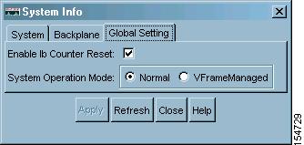
Configuring SystemOperMode
Configure SystemOperMode status to alter the behavior of the server switch to respond appropriately to a VFrame environment or a non-VFrame environment. To configure SystemOperMode, follow these steps:
Step 1
The System Info window opens.
Step 2
Figure 5-1 Global Settings
Step 3
•
•
Step 4
Configuring Date and Time Properties
An internal clock runs on your device, but we recommend that you configure your device to access a Network Time Protocol (NTP) server to synchronize your device with your network.
These topics describe how to configure date and time properties:
•
Configuring the Date and Time
To configure the date and time of the internal clock on your device, follow these steps:
Step 1
The Date and Time Properties window opens. The Date and Time tab appears by default.
Step 2
Step 3
Step 4
Assigning NTP Servers
To assign an NTP server to synchronize your server switch with the network, follow these steps:
Step 1
The Date and Time Properties window opens.
Step 2
Step 3
Step 4
Step 5
Note
Configuring the Local Time Zone and Daylight Savings Time
You can configure the time zone and daylight savings time either by selecting from a pre-configured list of time zones, or you can name and configure the details the of the time zone manually. These topics describe how to perform these tasks:
•
•
Configuring the Time Zone and Daylight Savings Time Manually
To configure the time zone or daylight savings time manually, follow these steps:
Step 1
The Date and Time Properties window appears.
Step 2
Step 3
a.
For example, if your server switch is located in the Pacific time zone, enter PST. This string appears in subsequent messages that display the time.
b.
For Pacific Standard Time, for example, enter - 8.
Step 4
a.
For example, in the Pacific time zone, enter PDT. For the period for which daylight savings time is active, this string appears in messages that display the time.
b.
c.
The format for the date is mm/dd/yyyy.
d.
The format for the date is mm/dd/yyyy.
e.
The format for the time is hh:mm on a 24-hour clock.
f.
The format for the time is hh:mm on a 24-hour clock.
Step 5
Configuring the Time Zone and Daylight Savings Time from a Preconfigured List
To configure the time zone or daylight savings time from a preconfigured list, follow these steps:
Step 1
The Date and Time Properties window appears.
Step 2
Step 3
The Time Zones window appears.
Step 4
Step 5
Step 6
Step 7
Configuring Basic Services
These topics describe how to configure basic services to facilitate remote access to your device:
•
•
•
•
•
•
Assigning a DNS Server
To assign a DNS server to your device, follow these steps:
Step 1
The Services window opens.
Step 2
Step 3
Step 4
Step 5
Enabling or Disabling the FTP Access
To enable or disable FTP access to and from your device, follow these steps:
Step 1
The Services window opens.
Step 2
Step 3
Enabling or Disabling the Telnet Access
To enable or disable Telnet access to your device, follow these steps:
Step 1
The Services window opens.
Step 2
Step 3
Assigning a Syslog Server
Note
To assign a syslog server to store logs from your device, follow these steps:
Step 1
The Services window opens.
Step 2
Step 3
Repeat this step to add a second server to Remote Syslog Server Two.
Viewing an Authentication Method
Note
To view an authentication method specific to your device, follow these steps:
Step 1
The Services window opens.
Step 2
Table 5-4 describes the fields under Authentication tab.
Table 5-4 Authentication Fields
Authentication Method
Indicates the authentication method.
Viewing and Managing RADIUS Servers
These topics describe how to view and manage RADIUS servers:
•
Viewing RADIUS Servers
To view the RADIUS servers that you have configured your device to use to authenticate CLI and Element Manager logins, follow these steps:
Step 1
The Services window opens.
Step 2
Table 5-5 describes the fields in the Radius Servers table.
Adding RADIUS Servers
To add a new RADIUS server on your device, follow these steps:
Step 1
The Services window opens.
Step 2
Step 3
The Insert Radius Server window opens.
Note
Step 4
Step 5
The numbers to the right of the field indicate the range of integer values that this field supports.
Step 6
Step 7
The numbers to the right of the field indicate the range of integer values that this field supports.
Step 8
The numbers to the right of the field indicate the range of integer values that this field supports.
Step 9
Editing a RADIUS Server Configuration
To edit a RADIUS server in your configuration, follow these steps:
Step 1
The Services window opens.
Step 2
Step 3
Note
Step 4
Step 5
Deleting RADIUS Servers
To delete a RADIUS server from your configuration, follow these steps:
Step 1
The Services window opens.
Step 2
Step 3
Step 4
Viewing and Managing TACACS+ Servers
These topics describe how to view and manage TACACS+ servers:
•
Viewing TACACS+ Servers
To view the TACACS+ servers that you have configured your device to use to authenticate CLI and Element Manager logins, follow these steps:
Step 1
The Services window opens.
Step 2
Table 5-6 describes the fields in the TACACS+ Servers table.
Adding a TACACS+ Server
To add a TACACS+ server to your device, follow these steps:
Step 1
The Services window opens.
Step 2
Step 3
Step 4
Step 5
Step 6
Step 7
Step 8
Step 9
Editing a TACACS+ Server Configuration
To edit a TACACS+ server, follow these steps:
Step 1
The Services window opens.
Step 2
Step 3
Note
Step 4
Step 5
Deleting a TACACS+ Server
To delete a TACACS+ server from your device, follow these steps:
Step 1
The Services window opens.
Step 2
Step 3
Step 4
Enabling HTTP Services
To configure HTTP services, follow these steps:
Step 1
The Services window opens.
Step 2
Step 3
Step 4
Step 5
Step 6
Step 7
Step 8
Step 9
Configuring Cisco Discovery Protocol
Cisco Discovery Protocol discovers information on neighbors and status. To configure CDC services, follow these steps:
Step 1
The Services window opens.
Step 2
Step 3
Step 4
Step 5
Step 6
Viewing the Discovery Cache
To view the discovery cache, follow these steps:
Step 1
The Services window opens.
Step 2
Customizing the Boot Configuration
To customize the boot configuration follow these steps:
•
•
•
These topics describe how to perform the following tasks:
•
Configuring Reboot Image
To choose the image that the server switch loads when it reboots, follow these steps:
Step 1
The Boot Configuration window opens.
Step 2
Step 3
Note
Deleting or Overwriting the Startup Configuration
To delete or overwrite the startup configuration, follow these steps:
Step 1
The Boot Configuration window opens.
Step 2
Note
Step 3
Step 4
Backing Up the Running Configuration File
To back up your running configuration file, follow these steps:
Step 1
The Backup Configuration window opens.
Step 2
Element Manager saves the running configuration in the configuration directory that you specify.
Note
Step 3
Viewing and Deleting Files in the File System
These topics describe file system tasks and concepts:
•
•
•
Viewing Files in the File System
To view files, such as image files, log files, and configuration files, that reside on your device, follow these steps:
Step 1
The File Management window opens. Table 5-7 describes the fields in the Current Files on System table in this window.
Step 2
Deleting Files in the File System
To delete files from your file system, follow these steps:
Step 1
The File Management window opens.
Step 2
A Delete File window opens.
Step 3
Understanding Configuration Files
A configuration file is a text file that stores a list of CLI commands. These topics describe specific instances of configuration files:
startup-config File
The main configuration file is called startup-config. This file stores all of the CLI commands necessary to completely configure a box from a factory-default state. This configuration file can be copied, backed up, and modified.
running-config File
Whenever configuration changes are made through the GUI or CLI, a CLI command is temporarily saved in a virtual configuration file called running-config. If you want to save these changes permanently, this file is copied into the startup-config file.
Any number of configuration files can be stored. For convenience and rapid configuration, files can also maintain a partial list of CLI commands. These files can also be copied into running-config for immediate use or startup-config for persistent use across reboots.
Understanding Log Files
Log files are text files that record activity, including configuration changes. Depending on their size, log files are rotated and compressed. Log files can also be exported from the system by using the copy command. These topics provide details about log files:
•
File Management and Storage of Log Files
The management of log files is performed automatically, but you can configure log files. Log files are stored separately from other file types, but all files share the 128 MB of flash memory. Log files are stored in syslog files.
The system checks the size of the active log file hourly, and when it exceeds 1 MB, the active log file, ts_log, is closed, compressed, and renamed ts_log.1.gz. Other ts_log.x.gz files are incremented by 1. These files can be downloaded through the Log Viewer GUI, which can create filters for troubleshooting and auditing purposes.
Log Message Types
The following levels of logging are captured:
•
•
•
•
•
•
Installing Software Images
Note
The image data that is used to configure the software is being continuously updated and enhanced. Use the latest system image data to ensure the most efficient operation of your system.
See the user's support portal at support.cisco.com for the latest upgrades.
These topics describe concepts and procedures related to installing a system image:
•
System Image
A system image is an unpacked and installed image file. An image file is the source from which to install a system image and it has an .img extension.
When an image file is installed, the image file is expanded into a system image. The system image is what the user will see in order to specify what the system should use to boot up each card in the system.
Image File
Image files are stored in flash memory as a single complete file with an .img extension. Each image file contains all the operating software (application software and firmware/microcode) needed by the various cards that can be installed into the system.
The system cannot use an image file directly to boot up the system. The image file must first be installed. The installation process automatically unbundles the image file and distributes the software components to each card in the system. Users do not have to be aware of individual software components. The user enters one CLI command to install an image file. See the install command in the Cisco SFS Product Family Command Reference.
The server switch operating system stores up to three images on a disk: the uninstalled image, the current system (or installed) image, and the recovery image.
The system has only enough flash memory to store:
•
•
•
Occasionally, you need to manually delete an image file from the InfiniBand system to make room for a new version. See the "Deleting Files in the File System" section.
These topics describe image concepts:
Inactive Image
An inactive image is an image that has been downloaded but has not been installed. It is not the active or system image.
The operating system can store only one inactive image. Delete inactive images through the CLI (see the "Deleting Files in the File System" section), or by clicking delete in the Element Manager.
Active Image
An active image is the current system image. An installed or active image has gone through the entire upgrade process. The system image usually has a slash (/) in its name. Do not modify or delete the installed system image.
Recovery Image
The recovery image is a default image that comes installed on the system. The recovery image can be used to quickly restore operation to the system if an image upgrade should fail.
Version Numbers
The operating system and installed system image running on the InfiniBand system determine the supported software features.
Two types of systemimages are provided:
•
•
Before configuring the InfiniBand system, check the version of the installed system image used to boot the chassis. Use this information to ensure that you upgrade to the correct software.
Copying and Downloading the Image
Upgrading the server switch operating system requires several steps, which are described in the following sections. Note that one step is to copy the image before installing it.
Table 5-8 describes several options for copying the image into the system.
Table 5-8 Copying and Downloading Image Options
FTP
Remote FTP Server
TFTP
Local File
SCP
Remote Secure Server
Card Status Requirements
Only cards with an oper-status of up are updated. If a card is down when you run install or a card is added after running install, follow these steps:
Step 1
Step 2
Step 3
If the image is already installed on a card, installation skips that card.
Step 4
Upgrading a System
To upgrade a system, follow these steps:
Step 1
Step 2
Step 3
Step 4
Step 5
Step 6
Installing a Software Image
Note
To install a software image file, follow these steps:
Step 1
The File Management window opens.
Note
Step 2
A select window opens prompting you to select the partition to install.
Step 3
Step 4
Note
Note
Importing Configuration Files and Image Files
These topics describe how to import files to your server switch from your local host or a remote FTP server:
•
•
Importing from a Remote FTP Server
To import files to your server switch from remote devices, follow these steps:
Step 1
The File Management window opens.
Step 2
The Import File window opens.
Step 3
Step 4
Step 5
Step 6
Step 7
Step 8
Step 9
Step 10
Importing from Your Local Host
To import files to your server switch from your local host, follow these steps:
Step 1
The File Management window opens.
Step 2
The Import File window opens.
Step 3
Step 4
Step 5
Step 6
Step 7
Step 8
Exporting Configuration Files and Log Files
These topics describe how to export files from your server switch to your local host or a remote FTP server:
Exporting to a Remote Server
To export files from your server switch to a remote server, follow these steps:
Step 1
The File Management window opens.
Step 2
The Export button becomes active.
Step 3
The Export File window opens.
Step 4
Step 5
Step 6
Step 7
Step 8
/root/files/old-config.cfgStep 9
Exporting to Your Local Host
To export files from your server switch to your local host, follow these steps:
Step 1
The File Management window opens.
Step 2
The Export button becomes active.
Step 3
The Export File window opens.
Step 4
Step 5
Step 6
Step 7
Saving a Configuration File
To back up your running configuration to the standby controller on your chassis, click the Maintenance menu, and choose Save Config.
Note
Rebooting the Server Switch with Element Manager
To reboot your server switch with Element Manager, follow these steps:
Step 1
Step 2
Running General Diagnostics
These topics describe how to run chassis, card, and port diagnostics:
•
Note
Running Chassis Diagnostics
To run chassis diagnostics, follow these steps:
Step 1
Step 2
Step 3
Step 4
Step 5
Step 6
Step 7
Step 8
Step 9
Running Card Diagnostics
To run card diagnostics, follow these steps:
Step 1
Step 2
Step 3
The diagnostic Insert Card window opens.
Step 4
Step 5
Step 6
Step 7
•
•
Step 8
Deleting a Card Test Entry
To delete a card test entry, follow these steps:
Step 1
Step 2
Step 3
Running Port Diagnostics
To run port diagnostics, follow these steps:
Step 1
Step 2
Step 3
The Diagnostic Insert Port window opens.
Step 4
Step 5
Step 6
Step 7
Step 8
Step 9
Step 10
Step 11
Step 12
•
•
Step 13
Deleting a Port Test Entry
To delete a port test entry, follow these steps:
Step 1
Step 2
Step 3
Running Configured Diagnostic Tests
To run a diagnostic test that you have already added to the Diagnostics window, follow these steps:
Step 1
Step 2
Step 3
Step 4
Note
Step 5
Viewing POST Diagnostics
These topics describe how to view power-on self-test diagnostics for cards, power supplies, and fans:
•
•
Viewing Card POST Diagnostics
To view card power-on self-test diagnostics, follow these steps:
Step 1
Step 2
Table 5-9 describes the fields that appear.
Viewing Power Supply POST Diagnostics
To view power supply power-on self-test (POST) diagnostics, follow these steps:
Step 1
Step 2
Table 5-10 describes the power supply POST fields that appear.
Viewing Fan POST Diagnostics
To view fan power-on self-test diagnostics, follow these steps:
Step 1
Step 2
Table 5-11 describes the fan POST fields that appear.
Viewing FRU Diagnostics
These topics describe how to view field-replaceable unit diagnostics for cards, power supplies, and fans:
•
Viewing Card FRU Diagnostics
To view card field-replaceable unit diagnostics, follow these steps:
Step 1
Step 2
Table 5-12 describes the card FRU fields that appear.
Viewing Power Supply FRU Diagnostics
To view power supply field-replaceable unit diagnostics, follow these steps:
Step 1
Step 2
Table 5-13 describes the power supply FRU fields that appear.
Viewing Fan FRU Diagnostics
To view fan field-replaceable unit diagnostics, follow these steps:
Step 1
Step 2
Table 5-14 describes the fan FRU fields that appear.