Cisco Small Business ISA500 Series Security Appliances Administration Guide (HTML)
Getting Started

Table Of Contents

Getting Started

Introduction

Product Overview

Front Panel

Back Panel

Getting Started with the Configuration Utility

Logging in to the Configuration Utility

Navigating Through the Configuration Utility

Using the Help System

Configuration Utility Icons

Factory Default Settings

Default Settings of Key Features

Restoring the Factory Default Settings

Performing Basic Configuration Tasks

Changing the Default Administrator Password

Upgrading your Firmware After your First Login

Backing Up Your Configuration


Getting Started


This chapter provides an overview of the Cisco ISA500 Series Integrated Security Appliance and describes basic configuration tasks to help you configure your security appliance. It includes the following sections:

Introduction

Product Overview

Getting Started with the Configuration Utility

Factory Default Settings

Performing Basic Configuration Tasks


NOTE For information about how to physically install your security appliance, see the Cisco ISA500 Series Integrated Security Appliances Quick Start Guide at: www.cisco.com/go/isa500resources.


Introduction

Thank you for choosing the Cisco ISA500 Series Integrated Security Appliance, a member of the Small Business Family. The ISA500 Series is a set of Unified Threat Management (UTM) security appliances that provide business-class security gateway solutions with dual WAN, DMZ, zone-based firewall, site-to-site and remote access VPN (including IPsec Remote Access, Teleworker VPN Client, and SSL VPN) support, and Internet threat protection, such as Intrusion Prevention (IPS), Anti-Virus, Application Control, Web URL Filtering, Web Reputation Filtering, Spam Filter, and Network Reputation. The ISA550W and ISA570W include 802.11b/g/n access point capabilities.

The following table lists the available model numbers.

Model
Description
Configuration
ISA550

Cisco ISA550 Integrated Security Appliance

1 WAN port, 2 LAN ports, 4 configurable ports, and 1 USB 2.0 port

ISA550W

Cisco ISA550 Integrated Security Appliance with Wi-Fi

1 WAN port, 2 LAN ports, 4 configurable ports, 1 USB 2.0 port, and 802.11b/g/n

ISA570

Cisco ISA570 Integrated Security Appliance

1 WAN port, 4 LAN ports, 5 configurable ports, and 1 USB 2.0 port

ISA570W

Cisco ISA570 Integrated Security Appliance with Wi-Fi

1 WAN port, 4 LAN ports, 5 configurable ports, 1 USB 2.0 port, and 802.11b/g/n


NOTE Any configurable port can be configured to be a WAN, DMZ, or LAN port. Only one configurable port can be configured as a WAN port at a time. Up to 4 configurable ports can be configured as DMZ ports.


Product Overview

Before you use the security appliance, become familiar with the lights on the front panel and the ports on the rear panel.

Front Panel

Back Panel

Front Panel

ISA550 Front Panel

ISA550W Front Panel

ISA570 Front Panel

ISA570W Front Panel

Front Panel Lights

The following table describes the lights on the front panel of the security appliance. These lights are used for monitoring system activity.
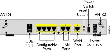
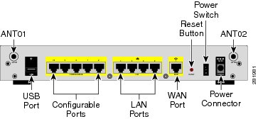
Light
Description
POWER/SYS

Indicates the power and system status.

Solid green when the system is powered on and is operating normally.

Flashes green when the system is booting.

Solid amber when the system has a booting problem, a device error occurs, or the system has a problem.

VPN

Indicates the site-to-site VPN connection status.

Solid green when there are active site-to-site VPN connections.

Flashes green when attempting to establish a site-to-site VPN tunnel.

Flashes amber when the system is experiencing problems setting up a site-to-site VPN connection and there is no VPN connection.

USB

Indicates the USB device status.

Solid green when a USB device is detected and is operating normally.

Flashes green when the USB device is transmitting and receiving data.

WLAN
(ISA550W and ISA570W only)

Indicates the WLAN status.

Solid green when the WLAN is up.

Flashes green when the WLAN is transmitting and receiving data.

SPEED

Indicates the traffic rate of the associated port.

Off when the traffic rate is 10 or 100 Mbps.

Solid green when the traffic rate is 1000 Mbps.

LINK/ACT

Indicates that a connection is being made through the port.

Solid green when the link is up.

Flashes green when the port is transmitting and receiving data.


Back Panel

The back panel is where you connect the network devices. The ports on the panel vary depending on the model.

ISA550 and ISA550W Back Panel

ISA570 and ISA570W Back Panel

Back Panel Descriptions

Feature
Description
ANT01/ANT02

Threaded connectors for the antennas (for ISA550W and ISA570W only).

USB Port

Connects the unit to a USB device. You can use a USB device to save and restore system configuration, or to upgrade the firmware.

Configurable Ports

Can be set to operate as WAN, LAN, or DMZ ports. ISA550 and ISA550W have 4 configurable ports. ISA570 and ISA570W have 5 configurable ports.

NOTE: Only one configurable port can be configured as a WAN port at a time. Up to 4 configurable ports can be configured as DMZ ports.

LAN Ports

Connects PCs and other network appliances to the unit. ISA550 and ISA550W have 2 dedicated LAN ports. ISA570 and ISA570W have 4 dedicated LAN ports.

WAN Port

Connects the unit to a DSL or a cable modem, or other WAN connectivity device.

RESET Button

To reboot the unit, push and release the RESET button for less than 3 seconds.

To restore the unit to its factory default settings, push and hold the RESET button for more than 3 seconds while the unit is powered on and the POWER/SYS light is solid green. The POWER/SYS light will flash green when the system is rebooting.

Power Switch

Powers the unit on or off.

Power Connector

Connects the unit to power using the supplied power cord and adapter.


Getting Started with the Configuration Utility

The ISA500 Series Configuration Utility is a web-based device manager that is used to provision the security appliance. To use this utility, you must be able to connect to the security appliance from a PC or laptop. You can access the Configuration Utility by using the following web browsers:

Microsoft Internet Explorer 8 and 9

Mozilla Firefox 3.6.x, 5, and 6


NOTE The minimum recommended display resolution for the PC running the Web browser used to access the Configuration Utility is 1024 x 768.


This section includes the following topics:

Logging in to the Configuration Utility

Navigating Through the Configuration Utility

Using the Help System

Configuration Utility Icons

Logging in to the Configuration Utility


STEP 1 Connect your computer to an available LAN port on the back panel.

Your PC will become a DHCP client of the security appliance and will receive an IP address in the 192.168.75.x range.

STEP 2 Start a web browser. In the address bar, enter the default IP address of the security appliance: 192.168.75.1.

NOTE: The above address is the factory default LAN address. If you change this setting, enter the new IP address to connect to the Configuration Utility.

STEP 3 When the login page opens, enter the username and password.

The default username is cisco. The default password is cisco. Usernames and passwords are case sensitive.

STEP 4 Click Login.

STEP 5 For security purposes, you must change the default password of the default administrator account. Set a new administrator password and click OK.

STEP 6 If you can access the Internet and a newer firmware is detected, the Firmware Upgrade window opens. Follow the on-screen prompts to download and install the firmware. See Upgrading your Firmware After your First Login.

STEP 7 If you cannot access the Internet or you are using the latest firmware, the Setup Wizard will now launch. Follow the on-screen prompts to complete the initial configuration. See Using the Setup Wizard for the Initial Configuration.


Navigating Through the Configuration Utility

Use the left hand navigation pane to perform the tasks in the Configuration Utility.

Number
Component
Description

1

Left Hand Navigation Pane

The left hand navigation pane provides easy navigation through the configurable features. The main branches expand to provide the features. Click the main branch title to expand its contents. Click the triangle next to a feature to expand or contract its sub-features. Click the title of a feature or sub-feature to open it.

2

Main Content

The main content of the feature or sub-feature appears in this area.


Using the Help System

The Configuration Utility provides a context-sensitive help file for all configuration tasks. To view the Help page, click the Help link in the top right corner of the screen. A new window opens with information about the page that you are currently viewing.

Configuration Utility Icons

The Configuration Utility has icons for commonly used configuration options. The following table describes these icons:

Icon
Description
Action

Add icon

Add an entry.

Edit icon

Edit an entry.

Duplicate icon

Create a copy of an existing entry.

Delete icon

Delete an entry or delete multiple selected entries.

Move icon

Move an item to a specific location.

Move down icon

Move an item down one position.

Move up icon

Move an item up one position.

Expand triangle icon

Expand the sub-features of a feature in the left navigation pane or expand the items under a category.

Contract triangle icon

Contract the sub-features of a feature in the left navigation pane or contract the items under a category.

Connect icon

Establish a VPN connection.

Disconnect or Logout icon

Terminate a VPN connection or an active user session.

Forced Authorized icon

Disable 802.1x access control and cause the port to transition to the authorized state without any authentication exchange required.

Forced Unauthorized icon

Cause the port to remain in the unauthorized state, ignoring all attempts by the client to authenticate.

Auto icon

Enable 802.1x access control and cause the port to begin in the unauthorized state, allowing only EAPOL frames to be sent and received through the port.

Import PC icon

Import a local certificate or a CA certificate from PC.

Export to USB or Import from USB icon

Export a local certificate, a CA certificate, or a Certificate Signing Request to a USB key, or import a local certificate or a CA certificate from a USB key.

Details icon

View the details of a certificate or a Certificate Signing Request.

Download icon

Download a local certificate, a CA certificate, or a Certificate Signing Request to PC.

Upload icon

Upload a signed certificate for the Certificate Signing Request from PC.

Install or Renew icon

Install the security license.

Refresh icon

Refresh the data.

Reset icon

Reset the device to the factory defaults, or renew the security license.

Check for Updates Now icon

Check for new signature updates from Cisco's signature server immediately.

Credentials icon

View the device credentials.

Email Alerts icon

View or configure the email alert settings.


Factory Default Settings

The security appliance is preconfigured with settings to allow you to start using the device with minimal changes. Depending on the requirements of your Internet Service Provider (ISP) and the needs of your business, you may need to modify some of these settings. You can use the Configuration Utility to customize all settings, as needed.

This section includes the following topics:

Default Settings of Key Features

Restoring the Factory Default Settings

Default Settings of Key Features

The default settings of key features are described below. For a full list of all factory default settings, see Factory Default Settings.

IP Routing Mode: By default, only the IPv4 mode is enabled. To support IPv4 and IPv6 addressing, enable the IPv4/IPv6 mode. See Configuring IPv4 or IPv6 Routing, page 116.

WAN Configuration: By default, the security appliance is configured to obtain an IP address from your ISP using Dynamic Host Configuration Protocol (DHCP). Depending on the requirement of your ISP, configure the network addressing mode for the primary WAN. You can change other WAN settings as well. See Configuring WAN Settings for Your Internet Connection, page 122.

LAN Configuration: By default, the LAN of the security appliance is configured in the 192.168.75.0 subnet and the LAN IP address is 192.168.75.1. The security appliance acts as a DHCP server to the hosts on the LAN network. It can automatically assign IP addresses and DNS server addresses to the PCs and other devices on the LAN. For most deployment scenarios, the default DHCP and TCP/IP settings should be satisfactory. However, you can change the subnet address or the default IP address. See Configuring a VLAN, page 137.

VLAN Configuration: The security appliance predefines a native VLAN (DEFAULT) and a guest VLAN (GUEST). You can customize the predefined VLANs or create new VLANs for your specific business needs. See Configuring a VLAN, page 137.

Configurable Ports: Any configurable port can be configured to be a WAN, DMZ, or LAN port. By default, all configurable ports are set to be LAN ports. Only one configurable port can be configured as a WAN port at a time (See Configuring the WAN, page 122). Up to four configurable ports can be configured as DMZ ports (see Configuring DMZ, page 141).

Wireless Network (for ISA550W and ISA570W only): ISA550W and ISA570W are configured with four SSIDs. All SSIDs are disabled by default. For security purposes, we strongly recommend that you configure the SSIDs with the appropriate security settings. See Wireless (for ISA550W and ISA570W only), page 206.

Administrative Access: You can access the Configuration Utility by using a web browser from the LAN side and entering the default LAN IP address of 192.168.75.1. You can log on by entering the username (cisco) and password (cisco) of the default administrator account. To prevent unauthorized access, you must immediately change the administrator password at the first login and are encouraged to change the username for the default administrator account. See Changing the Default Administrator Password.

Security Services: By default, the security services such as Intrusion Prevention (IPS), Anti-Virus, Application Control, Web URL Filtering, Web Reputation Filtering, and Spam Filter are disabled. See Chapter 7, "Security Services."

Firewall: By default, the firewall prevents inbound traffic and allows all outbound traffic. If you want to allow some inbound traffic or prevent some outbound traffic, you must customize firewall rules. Up to 100 custom firewall rules can be configured on the security appliance. See Configuring Firewall Rules to Control Inbound and Outbound Traffic, page 252.

VPN: By default, the VPN feature is disabled. The security appliance can function as an IPsec VPN server, a Teleworker VPN client, or as a SSL VPN gateway so that remote users can securely access the corporate network resources over the VPN tunnels. You can also establish a secure IPsec VPN tunnel between two sites that are physically separated by using the Site-to-Site VPN feature. See VPN.

Restoring the Factory Default Settings

To restore the factory defaults, choose one of the following actions:

Press and hold the RESET button on the back panel of the unit for more than 3 seconds while the unit is powered on and the POWER/SYS light is solid green. Release the button and wait for the unit to reboot. The POWER/SYS light will flash green when the system is rebooting.

Or launch the Configuration Utility and login. Click Device Management > Reboot/Reset in the left hand navigation pane. In the Reset Device area, click Reset to Factory Defaults.

After a restore to factory defaults, the following settings apply:

Parameter
Default Value

Username

cisco

Password

cisco

LAN IP

192.168.75.1

DHCP Range

192.168.75.100 to 200


Performing Basic Configuration Tasks

We recommend that you complete the following tasks before you configure the security appliance:

Changing the Default Administrator Password

Upgrading your Firmware After your First Login

Backing Up Your Configuration

Changing the Default Administrator Password

The default administrator account ("cisco") has full privilege to set the configuration and read the system status. For security purposes, you must change the default administrator password at the first login.


STEP 1 Enter the following information:

User name: Enter the current username or enter a new username if you want to change the default username.

New password: Enter a new administrator password. Passwords are case sensitive.

NOTE: A password requires a minimum of 8 characters, including at least three of these character classes: uppercase letters, lowercase letters, digits, and special characters. Do not repeat any password more than three times in a row. Do not set the password as the username or "cisco." Do not capitalize or spell these words backwards.

Confirm password: Enter the new administrator password again for confirmation.

STEP 2 Click OK to save your settings.


Upgrading your Firmware After your First Login

The security appliance uses a built-in IDA client to query the firmware from Cisco's IDA server. If a newer firmware is detected after you log in to the Configuration Utility for the first time, we recommend that you upgrade your firmware to the latest version before you do any other tasks. This feature requires that you have an active WAN connection to access the Internet.


STEP 1 Log in to the Configuration Utility for the first time and change the default administrator password. See Logging in to the Configuration Utility.

If newer firmware is detected, the Firmware Upgrade window opens. The version number for the firmware that you are currently using and the version number for the latest firmware that is detected are displayed.

STEP 2 Enter your Cisco.com account credentials in the Username and Password fields.

A valid Cisco.com account is required to download and install the firmware from Cisco.com. If you do not have one, go to this page:
https:// tools.cisco.com/RPF/register/register.do
Then click the Create a Cisco.com Account link to register a Cisco.com account.

NOTE: Skip this step if your Cisco.com account credentials are already configured on the security appliance.

STEP 3 Click Continue.

NOTE: You can click Install Later to upgrade the firmware later. An Upgrade Available link will be displayed at the top right corner of the screen and the Setup Wizard will now launch. We strongly recommend that you upgrade the firmware immediately.

STEP 4 Validate your Cisco.com account credentials through the Internet. If your Cisco.com account credentials are valid, the security appliance starts downloading and installing the firmware. This process will take several minutes.

STEP 5 The security appliance reboots after the firmware is upgraded. You will be redirected to the login screen when the security appliance boots up.

STEP 6 Log in to the Configuration Utility again. The Setup Wizard will launch. Follow the on-screen prompts to complete the initial configuration. See Using the Setup Wizard for the Initial Configuration.


NOTE Other options to upgrade the firmware:

If you cannot access the Internet after you log in to the Configuration Utility for the first time, you can use the Setup Wizard to configure your Internet connection and then automatically check for firmware updates after the Setup Wizard is complete. The Setup Wizard also allows you to manually upgrade the firmware from a firmware image stored on your local PC. See Using the Setup Wizard for the Initial Configuration.

You can manually upgrade the firmware from a firmware image stored on your PC or on a USB device. You must first download the latest firmware image from Cisco.com and save it to your local PC or to a USB device. See Upgrading Firmware from a PC or a USB Device, page 437.

The security appliance automatically checks for firmware updates from Cisco's IDA server every 24 hours. You can upgrade your firmware to the latest version if a newer firmware is available on Cisco.com. This feature requires that you have an active WAN connection and a valid Cisco.com account is configured on the security appliance in advance. See Upgrading your Firmware from Cisco.com, page 436.

Backing Up Your Configuration

At any point during the configuration process, you can back up your configuration. Later, if you make changes that you want to abandon, you can easily restore the saved configuration. See Backing Up and Restoring a Configuration, page 416.