-
Catalyst 6500 Series Switch and Cisco 7600 Series Router Firewall Services Module Configuration Guide, 2.2
-
About This Guide
-
Quick Start Steps
-
Introduction to the Firewall Services Module
-
Configuring the Switch for the Firewall Services Module
-
Connecting to the Firewall Services Module and Managing the Configuration
-
Configuring the Firewall Mode
-
Managing Security Contexts
-
Configuring Basic Settings
-
Configuring Bridging Parameters and ARP Inspection
-
Configuring IP Addresses, Routing, and DHCP
-
Configuring Network Address Translation
-
Controlling Network Access with Access Control Lists
-
Allowing Remote Management
-
Configuring AAA
-
Configuring Application and Protocol Inspection
-
Filtering HTTP, HTTPS, or FTP Requests Using an External Server
-
Using Failover
-
Managing Software and Configuration Files
-
Monitoring and Troubleshooting the Firewall Services Module
-
Specifications
-
Sample Configurations
-
Understanding the Command-Line Interface
-
Addresses, Protocols, and Ports Reference
-
Acronyms and Abbreviations
-
Index
-
 Feedback
Table Of Contents
Example 1: Security Contexts With Outside Access
Example 1: System Configuration
Example 1: Admin Context Configuration
Example 1: Customer A Context Configuration
Example 1: Customer B Context Configuration
Example 1: Customer C Context Configuration
Example 1: Switch Configuration
Example 2: Single Mode Using Same Security Level
Example 2: Switch Configuration
Example 3: Shared Resources for Multiple Contexts
Example 3: System Configuration
Example 3: Admin Context Configuration
Example 3: Department 1 Context Configuration
Example 3: Department 2 Context Configuration
Example 3: Switch Configuration
Example 4: Primary FWSM Configuration
Example 4: Secondary FWSM System Configuration
Example 4: Switch Configuration
Example 5: Security Contexts With Outside Access
Example 5: System Configuration
Example 5: Admin Context Configuration
Example 5: Customer A Context Configuration
Example 5: Customer B Context Configuration
Example 5: Customer C Context Configuration
Example 5: Switch Configuration
Example 6: Primary FWSM Configuration
Example 6: Secondary FWSM System Configuration
Example 6: Switch Configuration
Sample Configurations
This chapter illustrates and describes a number of common ways to implement the Firewall Services Module (FWSM). It includes the following topics:
Routed Mode Examples
This section includes the following topics:
•
Example 1: Security Contexts With Outside Access
•
•
Example 1: Security Contexts With Outside Access
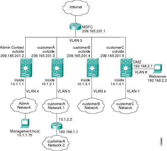
This configuration creates three security contexts plus the admin context, each with an inside and an outside interface. The Customer C context includes a DMZ interface where a Websense server for HTTP filtering resides on the service provider premises (see Figure B-1).
Inside hosts can access the Internet through the outside using dynamic NAT or PAT, but no outside hosts can access the inside.
The Customer A context has a second network behind an inside router.
The admin context allows SSH sessions to the FWSM from one host.
Each customer context belongs to a class that limits its resources (gold, silver, or bronze).
Although inside IP addresses can be the same across contexts when the VLANs are unique, keeping them unique is easier to manage.
Figure B-1 Example 1
See the following sections for the configurations for this scenario:
•
•
•
•
•
•
Example 1: System Configuration
You must first enable multiple context mode using the mode multiple command. Then enter the activation key to allow more than two contexts using the activation-key command. The mode and the activation key are not stored in the configuration file, even though they do endure reboots. If you view the configuration on the FWSM using the write terminal, show startup, or show running commands, the mode displays after the FWSM Version (blank means single mode, "<system>" means you are in multiple mode in the system configuration, and <context> means you are in multiple mode in a context).
hostname Farscapepassword passw0rdenable password chr1cht0nadmin-context admincontext adminallocate-interface vlan3allocate-interface vlan4config-url disk://admin.cfgclass defaultcontext customerAdescription This is the context for customer Aallocate-interface vlan3allocate-interface vlan5config-url disk://contexta.cfgclass goldcontext customerBdescription This is the context for customer Ballocate-interface vlan3allocate-interface vlan6config-url disk://contextb.cfgclass silvercontext customerCdescription This is the context for customer Callocate-interface vlan3allocate-interface vlan7-vlan8config-url disk://contextc.cfgclass bronzeclass goldlimit-resource all 7%limit-resource rate conns 2000limit-resource conns 20000class silverlimit-resource all 5%limit-resource rate conns 1000limit-resource conns 10000class bronzelimit-resource all 3%limit-resource rate conns 500limit-resource conns 5000Example 1: Admin Context Configuration
The host at 10.1.1.75 can access the context using SSH, which requires a certificate to be generated using the ca generate rsa key modulus command and saved using the ca save all command. The certificate is saved in Flash memory.
hostname Admindomain ispnameif vlan3 outside security0nameif vlan4 inside security100passwd secret1969enable password h1andl0ip address outside 209.165.201.2 255.255.255.224ip address inside 10.1.1.1 255.255.255.0route outside 0 0 209.165.201.1 1ssh 10.1.1.75 255.255.255.255 insidenat (inside) 1 10.1.1.0 255.255.255.0global (outside) 1 209.165.201.10-209.165.201.29 [This context uses dynamic NAT for inside users that access the outside]static (inside,outside) 209.165.201.30 10.1.1.75 netmask 255.255.255.255 [The host at 10.1.1.75 has access to the Websense server in Customer C, so it needs a static translation for use in Customer C's ACL]access-list INTERNET extended permit ip any anyaccess-group INTERNET in interface inside [Allows all inside hosts to access the outside for any IP traffic]Example 1: Customer A Context Configuration
nameif vlan3 outside security0nameif vlan5 inside security100passwd hell0!enable password enter55ip address outside 209.165.201.3 255.255.255.224ip address inside 10.1.2.1 255.255.255.0route outside 0 0 209.165.201.1 1route inside 192.168.1.0 255.255.255.0 10.1.2.2 1 [The Customer A context has a second network behind an inside router that requires a static route. All other traffic is handled by the default route pointing to the MSFC.]nat (inside) 1 10.1.2.0 255.255.255.0global (outside) 1 interface [This context uses dynamic PAT for inside users that access that outside. The outside interface address is used for the PAT address]access-list INTERNET extended permit ip any anyaccess-group INTERNET in interface inside [Allows all inside hosts to access the outside for any IP traffic]Example 1: Customer B Context Configuration
nameif vlan3 outside security0nameif vlan6 inside security100passwd tenac10usenable password defen$eip address outside 209.165.201.4 255.255.255.224ip address inside 10.1.3.1 255.255.255.0route outside 0 0 209.165.201.1 1nat (inside) 1 10.1.3.0 255.255.255.0global (outside) 1 209.165.201.9 netmask 255.255.255.255 [This context uses dynamic PAT for inside users that access the outside]access-list INTERNET extended permit tcp any any eq httpaccess-list INTERNET extended permit tcp any any eq httpsaccess-group INTERNET in interface inside [Inside users can only access HTTP and HTTPS servers on the outside]Example 1: Customer C Context Configuration
nameif vlan3 outside security0nameif vlan7 inside security100nameif vlan8 dmz security50passwd fl0werenable password treeh0u$eip address outside 209.165.201.5 255.255.255.224ip address inside 10.1.4.1 255.255.255.0ip address dmz 192.168.2.1 255.255.255.0route outside 0 0 209.165.201.1 1url-server (dmz) vendor websense host 192.168.2.2 url-block block 50url-cache dst 128filter url http 10.1.4.0 255.255.255.0 0 0 [When inside users access an HTTP server, the FWSM consults with a Websense server to determine if the traffic is allowed]nat (inside) 1 10.1.4.0 255.255.255.0global (outside) 1 209.165.201.9 netmask 255.255.255.255 [This context uses dynamic NAT for inside users that access the outside]static (dmz,outside) 209.165.201.6 192.168.2.2 netmask 255.255.255.255 [A host on the admin context requires access to the Websense server for management using pcAnywhere, so the Websense server requires a static translation]access-list INTERNET extended permit ip any anyaccess-group INTERNET in interface inside [Allows all inside hosts to access the outside for any IP traffic. Because there is no NAT from inside to dmz, you do not have to deny traffic from accessing the dmz.]access-list MANAGE extended permit tcp host 209.165.201.30 host 209.165.201.6 eq pcanywhere-dataaccess-list MANAGE extended permit udp host 209.165.201.30 host 209.165.201.6 eq pcanywhere-statusaccess-group MANAGE in interface outside [This ACL allows the management host to use pcAnywhere on the Websense server]access-list WEBSENSE extended permit tcp host 192.168.2.2 any eq http [The Websense server needs to access the Websense updater server on the outside]access-group WEBSENSE in interface dmzExample 1: Switch Configuration
The following lines in the Cisco IOS switch configuration relate to the FWSM:
...firewall module 8 vlan-group 1firewall vlan-group 1 3-8interface vlan 3ip address 209.165.201.1 255.255.255.224no shut...Example 2: Single Mode Using Same Security Level
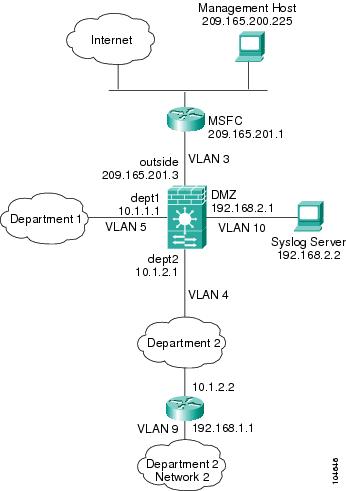
This configuration creates three internal interfaces. Two of the interfaces connect to departments that are on the same security level, which allows all hosts to communicate without using NAT. The DMZ interface hosts a Syslog server. The management host on the outside needs access to the Syslog server and the FWSM. To connect to the FWSM, the host uses a VPN connection. The FWSM uses RIP on the inside interfaces to learn routes. Because the FWSM does not advertise routes with RIP, the MSFC needs to use static routes for FWSM traffic (see Figure B-2).
The Department networks are allowed to access the Internet, and use PAT.
Figure B-2 Example 2
See the following sections for the configurations for this scenario:
•
•
Example 2: FWSM Configuration
nameif vlan3 outside security0nameif vlan4 dept2 security100nameif vlan5 dept1 security100nameif vlan10 dmz security50passwd g00fba11enable password gen1u$hostname Bustersame-security-traffic permit inter-interfaceip address outside 209.165.201.3 255.255.255.224ip address dept2 10.1.2.1 255.255.255.0ip address dept1 10.1.1.1 255.255.255.0ip address dmz 192.168.2.1 255.255.255.0route outside 0 0 209.165.201.1 1nat (dept1) 1 10.1.1.0 255.255.255.0nat (dept2) 1 10.1.2.0 255.255.255.0global (outside) 1 209.165.201.9 netmask 255.255.255.255 [The dept1 and dept2 networks use PAT when accessing the outside]static (dmz,outside) 209.165.201.5 192.168.2.2 netmask 255.255.255.255 [The syslog server needs a static translation so the outside management host can access the server]access-list DEPTS extended permit ip any anyaccess-group DEPTS in interface dept1access-group DEPTS in interface dept2 [Allows all dept1 and dept2 hosts to access the outside for any IP traffic]access-list MANAGE extended permit tcp host 209.165.200.225 host 209.165.201.5 eq telnetaccess-group MANAGE in interface outside [This ACL allows the management host to access the syslog server]rip dept2 default version 2 authentication md5 scorpius 1 [Advertises the FWSM IP address as the default gateway for the downstream router. The FWSM does not advertise a default route to the MSFC.]rip dept2 passive version 2 authentication md5 scorpius 1 [Listens for RIP updates from the downstream router. The FWSM does not listen for RIP updates from the MSFC because a default route to the MSFC is all that is required.]isakmp policy 1 authentication pre-share [The client uses a pre-shared key to connect to the FWSM over IPSec. The key is the password in the username command below.]isakmp policy 1 encryption 3desisakmp policy 1 group 2isakmp policy 1 hash shaisakmp enable outsidecrypto ipsec transform-set vpn_client esp-3des esp-sha-hmacusername admin password passw0rdcrypto ipsec transform-set vpn esp-3des esp-sha-hmaccrypto dynamic-map vpn_client 1 set transform-set vpncrypto map telnet_tunnel 1 ipsec-isakmp dynamic vpn_clientcrypto map telnet_tunnel interface outsidecrypto map telnet_tunnel client authentication LOCALip local pool client_pool 10.1.1.2access-list VPN_SPLIT extended permit ip host 209.165.201.3 host 10.1.1.2vpngroup admin address-pool client_poolvpngroup admin split-tunnel VPN_SPLITvpngroup admin password $ecure23telnet 10.1.1.2 255.255.255.255 outsidetelnet timeout 30logging trap 5logging host dmz 192.168.2.2 [System messages are sent to the syslog server on the DMZ network]logging onExample 2: Switch Configuration
The following lines in the switch configuration relate to the FWSM:
Catalyst OS on the supervisor:
set vlan 3-5,9,10 firewall-vlan 8Cisco IOS software on the MSFC:
interface vlan 3ip address 209.165.201.1 255.255.255.224no shut...Example 3: Shared Resources for Multiple Contexts
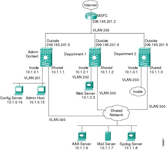
This configuration includes multiple contexts for multiple departments within a company. Each department has its own security context so that each department can have its own security policy. However, the syslog, mail, and AAA servers are shared across all departments. These servers are placed on a shared VLAN (see Figure B-3).
Department 1 has a web server that outside users who are authenticated by the AAA server can access.
Figure B-3 Example 3
See the following sections for the configurations for this scenario:
•
•
•
•
•
Example 3: System Configuration
You must first enable multiple context mode using the mode multiple command. Then enter the activation key to allow more than two contexts using the activation-key command. The mode and the activation key are not stored in the configuration file, even though they do endure reboots. If you view the configuration on the FWSM using the write terminal, show startup, or show running commands, the mode displays after the FWSM Version (blank means single mode, "<system>" means you are in multiple mode in the system configuration, and <context> means you are in multiple mode in a context).
hostname Ubikpassword pkd55enable password deckard69admin-context admincontext adminallocate-interface vlan200allocate-interface vlan201allocate-interface vlan300config-url disk://admin.cfgcontext department1allocate-interface vlan200allocate-interface vlan202allocate-interface vlan300config-url ftp://admin:passw0rd@10.1.0.16/dept1.cfgcontext department2allocate-interface vlan200allocate-interface vlan203allocate-interface vlan300config-url ftp://admin:passw0rd@10.1.0.16/dept2.cfgExample 3: Admin Context Configuration
hostname Adminnameif vlan200 outside security0nameif vlan201 inside security100nameif vlan300 shared security50passwd v00d00enable password d011ip address outside 209.165.201.3 255.255.255.224ip address inside 10.1.0.1 255.255.255.0ip address shared 10.1.1.1 255.255.255.0route outside 0 0 209.165.201.2 1nat (inside) 1 10.1.0.0 255.255.255.0global (outside) 1 209.165.201.6 netmask 255.255.255.255 [This context uses PAT for inside users that access the outside]global (shared) 1 10.1.1.30 [This context uses PAT for inside users that access the shared network]static (inside,outside) 209.165.201.7 10.1.0.15 netmask 255.255.255.255 [Because this host can access the web server in the Department 1 context, it requires a static translation]static (inside,shared) 10.1.1.78 10.1.0.15 netmask 255.255.255.255 [Because this host has management access to the servers on the Shared interface, it requires a static translation to be used in an ACL]access-list INTERNET extended permit ip any anyaccess-group INTERNET in interface inside [Allows all inside hosts to access the outside and shared network for any IP traffic]access-list SHARED extended permit ip host 10.1.1.78 anyaccess-list SHARED extended permit tcp host 10.1.1.30 host 10.1.1.7 eq smtpaccess-group SHARED out interface shared [This ACL allows only mail traffic from the inside network to exit out the shared interface, but allows the admin host to access any server. Note that the translated addresses are used.]telnet 10.1.0.15 255.255.255.255 inside [Allows 10.1.0.15 to access the admin context using Telnet. From the admin context, you can access all other contexts.]aaa-server AAA-SERVER protocol tacacs+aaa-server AAA-SERVER (shared) host 10.1.1.6 TheUauthKeyaaa authentication telnet console AAA-SERVER [The host at 10.1.0.15 must authenticate with the AAA server to log in]logging trap 6logging host shared 10.1.1.8 [System messages are sent to the syslog server on the Shared network]logging onExample 3: Department 1 Context Configuration
nameif vlan200 outside security0nameif vlan202 inside security100nameif vlan300 shared security50passwd cugelenable password rhialtoip address outside 209.165.201.4 255.255.255.224ip address inside 10.1.2.1 255.255.255.0ip address shared 10.1.1.2 255.255.255.0nat (inside) 1 10.1.2.0 255.255.255.0global (outside) 1 209.165.201.8 netmask 255.255.255.255 [The inside network uses PAT when accessing the outside]global (shared) 1 10.1.1.31-10.1.1.37 [The inside network uses dynamic NAT when accessing the shared network]static (inside,outside) 209.165.201.9 10.1.2.3 netmask 255.255.255.255 [The web server can be accessed from outside and requires a static translation]access-list INTERNET extended permit ip any anyaccess-group INTERNET in interface inside [Allows all inside hosts to access the outside and shared network for any IP traffic]access-list WEBSERVER extended permit ip host 209.165.201.7 host 209.165.201.9 [This ACE allows the management host (its translated address) on the admin context to access the web server for management (it can use any IP protocol)]access-list WEBSERVER extended permit tcp any eq http host 209.165.201.9 eq http [This ACE allows any outside address to access the web server with HTTP]access-group WEBSERVER in interface outsideaccess-list MAIL extended permit tcp host 10.1.1.31 eq smtp host 10.1.1.7 eq smtpaccess-list MAIL extended permit tcp host 10.1.1.32 eq smtp host 10.1.1.7 eq smtpaccess-list MAIL extended permit tcp host 10.1.1.33 eq smtp host 10.1.1.7 eq smtpaccess-list MAIL extended permit tcp host 10.1.1.34 eq smtp host 10.1.1.7 eq smtpaccess-list MAIL extended permit tcp host 10.1.1.35 eq smtp host 10.1.1.7 eq smtpaccess-list MAIL extended permit tcp host 10.1.1.36 eq smtp host 10.1.1.7 eq smtpaccess-list MAIL extended permit tcp host 10.1.1.37 eq smtp host 10.1.1.7 eq smtpaccess-group MAIL out interface shared [This ACL allows only mail traffic from the inside network to exit out the shared interface. Note that the translated addresses are used.]aaa-server AAA-SERVER protocol tacacs+aaa-server AAA-SERVER (shared) host 10.1.1.6 TheUauthKeyaaa authentication match WEBSERVER outside AAA-SERVER [All traffic matching the WEBSERVER ACL must authenticate with the AAA server]logging trap 4logging host shared 10.1.1.8 [System messages are sent to the syslog server on the Shared network]logging onExample 3: Department 2 Context Configuration
nameif vlan200 outside security0nameif vlan203 inside security100nameif vlan300 shared security50passwd maz1r1anenable password ly0ne$$eip address outside 209.165.201.5 255.255.255.224ip address inside 10.1.3.1 255.255.255.0ip address shared 10.1.1.3 255.255.255.0route outside 0 0 209.165.201.2 1nat (inside) 1 10.1.3.0 255.255.255.0global (outside) 1 209.165.201.10 netmask 255.255.255.255 [The inside network uses PAT when accessing the outside]global (shared) 1 10.1.1.38 [The inside network uses PAT when accessing the shared network]access-list INTERNET extended permit ip any anyaccess-group INTERNET in interface inside [Allows all inside hosts to access the outside and shared network for any IP traffic]access-list MAIL extended permit tcp host 10.1.1.38 host 10.1.1.7 eq smtpaccess-group MAIL out interface shared [This ACL allows only mail traffic from the inside network to exit out the shared interface. Note that the translated PAT address is used.]logging trap 3logging host shared 10.1.1.8 [System messages are sent to the syslog server on the Shared network]logging onExample 3: Switch Configuration
The following lines in the Cisco IOS switch configuration relate to the FWSM:
...firewall module 6 vlan-group 1firewall vlan-group 1 200-203,300interface vlan 200ip address 209.165.201.2 255.255.255.224no shut...Example 4: Failover
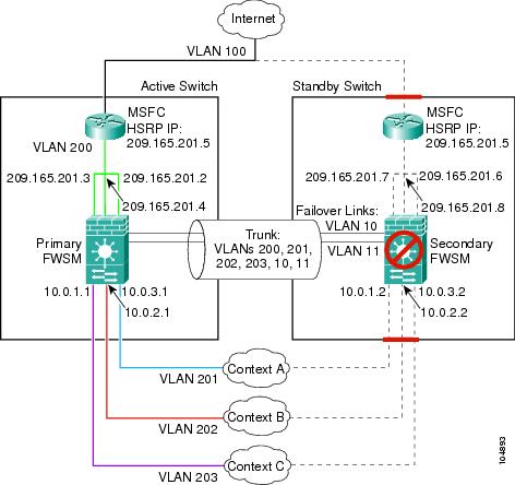
This configuration shows a routed, multiple context mode FWSM in one switch, and another FWSM in a second switch acting as a backup (see Figure B-4). Each context (A, B, and C) monitors the inside interface, and context A, which is the admin context, also monitors the outside interface. Because the outside interface is shared among all contexts, monitoring in one context benefits all contexts.
The secondary FWSM is also in routed, multiple context mode, and has the same software version.
Figure B-4 Example 4
See the following sections for the configurations for this scenario:
•
•
•
Example 4: Primary FWSM Configuration
The following sections include the configuration for the primary FWSM:
•
•
•
•
Example 4: System Configuration (Primary)
You must first enable multiple context mode using the mode multiple command. Then enter the activation key to allow more than two contexts using the activation-key command. The mode and the activation key are not stored in the configuration file, even though they do endure reboots. If you view the configuration on the FWSM using the write terminal, show startup, or show running commands, the mode displays after the FWSM Version (blank means single mode, "<system>" means you are in multiple mode in the system configuration, and <context> means you are in multiple mode in a context).
hostname primaryenable password farscapepassword crichtonfailover lan interface faillink vlan 10failover link statelink vlan 11failover lan unit primaryfailover interface ip faillink 192.168.253.1 255.255.255.252 standby 192.168.253.2failover interface ip statelink 192.168.253.5 255.255.255.252 standby 192.168.253.6failover interface-policy 50%failover replication httpfailoveradmin-context contextacontext contextaallocate-interface vlan200allocate-interface vlan201config-url disk://contexta.cfgcontext contextballocate-interface vlan200allocate-interface vlan202config-url ftp://admin:passw0rd@10.0.3.16/contextb.cfgcontext contextcallocate-interface vlan200allocate-interface vlan203config-url ftp://admin:passw0rd@10.0.3.16/contextc.cfgExample 4: Context A Configuration (Primary)
nameif vlan200 outside security0nameif vlan201 inside security100passwd secret1969enable password h1andl0ip address outside 209.165.201.2 255.255.255.224 standby 209.165.201.6ip address inside 10.0.3.1 255.255.255.0 standby 10.0.3.2monitor-interface insidemonitor-interface outsidenat (inside) 1 0.0.0.0 0.0.0.0 0 0global (outside) 1 209.165.201.10 netmask 255.255.255.224 [This context uses dynamic PAT for inside users that access the outside]route outside 0 0 209.165.201.5 1telnet 10.0.3.75 255.255.255.255 insideaccess-list INTERNET extended permit ip any anyaccess-group INTERNET in interface inside [Allows all inside hosts to access the outside for any IP traffic]Example 4: Context B Configuration (Primary)
nameif vlan200 outside security0nameif vlan202 inside security100passwd secret1978enable password 7samura1ip address outside 209.165.201.4 255.255.255.224 standby 209.165.201.8ip address inside 10.0.2.1 255.255.255.0 standby 10.0.2.2monitor-interface insidenat (inside) 1 0.0.0.0 0.0.0.0 0 0global (outside) 1 209.165.201.11 netmask 255.255.255.224 [This context uses dynamic PAT for inside users that access the outside]route outside 0 0 209.165.201.5 1telnet 10.0.2.14 255.255.255.255 insideaccess-list INTERNET extended permit ip any anyaccess-group INTERNET in interface inside [Allows all inside hosts to access the outside for any IP traffic]Example 4: Context C Configuration (Primary)
nameif vlan200 outside security0nameif vlan203 inside security100passwd secret0997enable password strayd0gip address outside 209.165.201.3 255.255.255.224 standby 209.165.201.7ip address inside 10.0.1.1 255.255.255.0 standby 10.0.1.2monitor-interface insidenat (inside) 1 0.0.0.0 0.0.0.0 0 0global (outside) 1 209.165.201.12 netmask 255.255.255.224 [This context uses dynamic PAT for inside users that access the outside]route outside 0 0 209.165.201.5 1telnet 10.0.1.65 255.255.255.255 insideaccess-list INTERNET extended permit ip any anyaccess-group INTERNET in interface inside [Allows all inside hosts to access the outside for any IP traffic]Example 4: Secondary FWSM System Configuration
You do not need to configure any contexts, just the following minimal configuration for the system.
You must first enable multiple context mode using the mode multiple command. Then enter the activation key to allow more than two contexts using the activation-key command. The mode and the activation key are not stored in the configuration file, even though they do endure reboots. If you view the configuration on the FWSM using the write terminal, show startup, or show running commands, the mode displays after the FWSM Version (blank means single mode, "<system>" means you are in multiple mode in the system configuration, and <context> means you are in multiple mode in a context).
failover lan interface faillink vlan 10failover interface ip faillink 192.168.253.1 255.255.255.252 standby 192.168.253.2failover lan unit secondaryfailoverExample 4: Switch Configuration
The following lines in the Cisco IOS switch configuration on both switches relate to the FWSM. For information about configuring redundancy for the switch, see the switch documentation.
...firewall module 1 vlan-group 1firewall vlan-group 1 10,11,200-203interface vlan 200ip address 209.165.201.1 255.255.255.224standby 200 ip 209.165.201.5standby 200 priority 110standby 200 preemptstandby 200 timers 5 15standby 200 authentication Secretno shutinterface range gigabitethernet 2/1-3channel-group 2 mode onswitchport trunk encapsulation dot1qno shut...Transparent Mode Examples
This section includes the following topics:
•
Example 5: Security Contexts With Outside Access
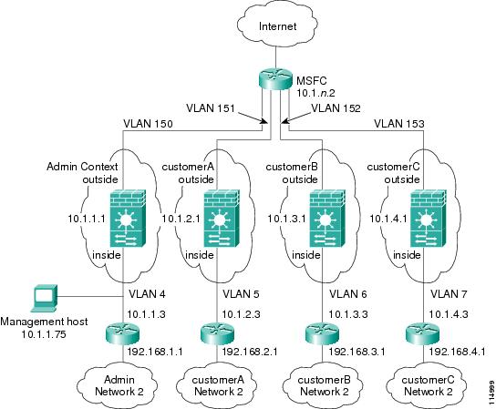
This configuration creates three security contexts plus the admin context. Each context allows OSPF traffic to pass between the inside and outside routers (see Figure B-5).
Inside hosts can access the Internet through the outside, but no outside hosts can access the inside.
The admin context allows SSH sessions to the FWSM from one host.
Each customer context belongs to a class that limits its resources (gold, silver, or bronze).
Although inside IP addresses can be the same across contexts, keeping them unique is easier to manage.
Figure B-5 Example 5
See the following sections for the configurations for this scenario:
•
•
•
•
•
•
•
Example 5: System Configuration
You must first enable multiple context mode using the mode multiple command. Then enter the activation key to allow more than two contexts using the activation-key command. The mode and the activation key are not stored in the configuration file, even though they do endure reboots. If you view the configuration on the FWSM using the write terminal, show startup, or show running commands, the mode displays after the FWSM Version (blank means single mode, "<system>" means you are in multiple mode in the system configuration, and <context> means you are in multiple mode in a context).
firewall transparenthostname Farscapepassword passw0rdenable password chr1cht0nadmin-context admincontext adminallocate-interface vlan150allocate-interface vlan4config-url disk://admin.cfgclass defaultcontext customerAdescription This is the context for customer Aallocate-interface vlan151allocate-interface vlan5config-url disk://contexta.cfgclass goldcontext customerBdescription This is the context for customer Ballocate-interface vlan152allocate-interface vlan6config-url disk://contextb.cfgclass silvercontext customerCdescription This is the context for customer Callocate-interface vlan153allocate-interface vlan7config-url disk://contextc.cfgclass bronzeclass goldlimit-resource all 7%limit-resource rate conns 2000limit-resource conns 20000class silverlimit-resource all 5%limit-resource rate conns 1000limit-resource conns 10000class bronzelimit-resource all 3%limit-resource rate conns 500limit-resource conns 5000Example 5: Admin Context Configuration
The host at 10.1.1.75 can access the context using SSH, which requires a certificate to be generated using the ca generate rsa key modulus command and saved using the ca save all command. The certificate is saved in Flash memory.
hostname Admindomain ispnameif vlan150 outside security0nameif vlan4 inside security100passwd secret1969enable password h1andl0ip address 10.1.1.1 255.255.255.0route outside 0 0 10.1.1.2 1ssh 10.1.1.75 255.255.255.255 insideaccess-list INTERNET extended permit 89 any anyaccess-list INTERNET extended permit ip any anyaccess-list OSPF extended permit 89 any anyaccess-group INTERNET in interface inside [Allows all inside hosts to access the outside for any IP traffic. Also allows OSPF.]access-group OSPF in interface outside [Allows OSPF.]Example 5: Customer A Context Configuration
nameif vlan151 outside security0nameif vlan5 inside security100passwd hell0!enable password enter55ip address 10.1.2.1 255.255.255.0route outside 0 0 10.1.2.2 1access-list INTERNET extended permit 89 any anyaccess-list INTERNET extended permit ip any anyaccess-list OSPF extended permit 89 any anyaccess-group INTERNET in interface inside [Allows all inside hosts to access the outside for any IP traffic. Also allows OSPF.]access-group OSPF in interface outside [Allows OSPF.]Example 5: Customer B Context Configuration
nameif vlan152 outside security0nameif vlan6 inside security100passwd tenac10usenable password defen$eip address 10.1.3.1 255.255.255.0route outside 0 0 10.1.3.2 1access-list INTERNET extended permit 89 any anyaccess-list INTERNET extended permit ip any anyaccess-list OSPF extended permit 89 any anyaccess-group INTERNET in interface inside [Allows all inside hosts to access the outside for any IP traffic. Also allows OSPF.]access-group OSPF in interface outside [Allows OSPF.]Example 5: Customer C Context Configuration
nameif vlan153 outside security0nameif vlan7 inside security100passwd fl0werenable password treeh0u$eip address 10.1.4.1 255.255.255.0route outside 0 0 10.1.4.2 1access-list INTERNET extended permit 89 any anyaccess-list INTERNET extended permit ip any anyaccess-list OSPF extended permit 89 any anyaccess-group INTERNET in interface inside [Allows all inside hosts to access the outside for any IP traffic. Also allows OSPF.]access-group OSPF in interface outside [Allows OSPF.]Example 5: Switch Configuration
The following lines in the Cisco IOS switch configuration relate to the FWSM:
...firewall multiple-vlan-interfacesfirewall module 8 vlan-group 1firewall vlan-group 1 4-7,150-153interface vlan 150ip address 10.1.1.2 255.255.255.0no shutinterface vlan 151ip address 10.1.2.2 255.255.255.0no shutinterface vlan 152ip address 10.1.3.2 255.255.255.0no shutinterface vlan 153ip address 10.1.4.2 255.255.255.0no shut...Example 6: Failover
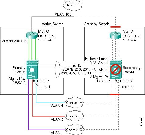
This configuration shows a transparent, multiple context mode FWSM in one switch, and another FWSM in a second switch acting as a backup (see Figure B-4). Each context (A, B, and C) monitors the inside interface and outside interface.
The secondary FWSM is also in transparent, multiple context mode, and has the same software version.
Figure B-6 Example 6
See the following sections for the configurations for this scenario:
•
•
•
Example 6: Primary FWSM Configuration
The following sections include the configuration for the primary FWSM:
•
•
•
•
Example 6: System Configuration (Primary)
You must first enable multiple context mode using the mode multiple command. Then enter the activation key to allow more than two contexts using the activation-key command. The mode and the activation key are not stored in the configuration file, even though they do endure reboots. If you view the configuration on the FWSM using the write terminal, show startup, or show running commands, the mode displays after the FWSM Version (blank means single mode, "<system>" means you are in multiple mode in the system configuration, and <context> means you are in multiple mode in a context).
firewall transparenthostname primaryenable password farscapepassword crichtonfailover lan interface faillink vlan 10failover link statelink vlan 11failover lan unit primaryfailover interface ip faillink 192.168.253.1 255.255.255.252 standby 192.168.253.2failover interface ip statelink 192.168.253.5 255.255.255.252 standby 192.168.253.6failover interface-policy 1failover replication httpfailoveradmin-context contextacontext contextaallocate-interface vlan200allocate-interface vlan4config-url disk://contexta.cfgcontext contextballocate-interface vlan201allocate-interface vlan5config-url ftp://admin:passw0rd@10.0.3.16/contextb.cfgcontext contextcallocate-interface vlan202allocate-interface vlan6config-url ftp://admin:passw0rd@10.0.3.16/contextc.cfgExample 6: Context A Configuration (Primary)
nameif vlan200 outside security0nameif vlan4 inside security100passwd secret1969enable password h1andl0ip address 10.0.3.1 255.255.255.0 standby 10.0.3.2monitor-interface insidemonitor-interface outsideroute outside 0 0 10.0.3.4 1telnet 10.0.3.75 255.255.255.255 insideaccess-list INTERNET extended permit ip any anyaccess-group INTERNET in interface inside [Allows all inside hosts to access the outside for any IP traffic]access-list BPDU ethertype permit bpduaccess-group BPDU in interface insideaccess-group BPDU in interface outsideExample 6: Context B Configuration (Primary)
nameif vlan201 outside security0nameif vlan5 inside security100passwd secret1978enable password 7samura1ip address inside 10.0.2.1 255.255.255.0 standby 10.0.2.2monitor-interface insidemonitor-interface outsideroute outside 0 0 10.0.2.4 1telnet 10.0.2.14 255.255.255.255 insideaccess-list INTERNET extended permit ip any anyaccess-group INTERNET in interface inside [Allows all inside hosts to access the outside for any IP traffic]access-list BPDU ethertype permit bpduaccess-group BPDU in interface insideaccess-group BPDU in interface outsideExample 6: Context C Configuration (Primary)
nameif vlan202 outside security0nameif vlan6 inside security100passwd secret0997enable password strayd0gip address inside 10.0.1.1 255.255.255.0 standby 10.0.1.2monitor-interface insidemonitor-interface outsideroute outside 0 0 10.0.1.4 1telnet 10.0.1.65 255.255.255.255 insideaccess-list INTERNET extended permit ip any anyaccess-group INTERNET in interface inside [Allows all inside hosts to access the outside for any IP traffic]access-list BPDU ethertype permit bpduaccess-group BPDU in interface insideaccess-group BPDU in interface outsideExample 6: Secondary FWSM System Configuration
You do not need to configure any contexts, just the following minimal configuration for the system.
You must first enable multiple context mode using the mode multiple command. Then enter the activation key to allow more than two contexts using the activation-key command. The mode and the activation key are not stored in the configuration file, even though they do endure reboots. If you view the configuration on the FWSM using the write terminal, show startup, or show running commands, the mode displays after the FWSM Version (blank means single mode, "<system>" means you are in multiple mode in the system configuration, and <context> means you are in multiple mode in a context).
firewall transparentfailover lan interface faillink vlan 10failover interface ip faillink 192.168.253.1 255.255.255.252 standby 192.168.253.2failover lan unit secondaryfailoverExample 6: Switch Configuration
The following lines in the Cisco IOS switch configuration on both switches relate to the FWSM. For information about configuring redundancy for the switch, see the switch documentation.
...firewall multiple-vlan-interfacesfirewall module 1 vlan-group 1firewall vlan-group 1 4-6,10,11,200-202interface vlan 200ip address 10.0.1.3 255.255.255.0standby 200 ip 10.0.1.4standby 200 priority 110standby 200 preemptstandby 200 timers 5 15standby 200 authentication Secretno shutinterface vlan 201ip address 10.0.2.3 255.255.255.0standby 200 ip 10.0.2.4standby 200 priority 110standby 200 preemptstandby 200 timers 5 15standby 200 authentication Secretno shutinterface vlan 202ip address 10.0.3.3 255.255.255.0standby 200 ip 10.0.3.4standby 200 priority 110standby 200 preemptstandby 200 timers 5 15standby 200 authentication Secretno shutinterface range gigabitethernet 2/1-3channel-group 2 mode onswitchport trunk encapsulation dot1qno shut...