Table Of Contents
Maintenance and Upgrade Procedures
Removing and Replacing the Chassis Cover
Working in an ESD Environment
Removing the Chassis Cover
Replacing the Chassis Cover
Replacing the Lithium Battery
Installing and Replacing the SSC
Installing an SSC
Replacing an SSC
Upgrading Memory
Removing the DIMM
Installing the DIMM
Verifying the Memory Upgrade
Maintenance and Upgrade Procedures
This chapter describes how to install the chassis on the wall or rack, remove and replace the chassis cover, the power supply, and the CompactFlash. This chapter includes the following sections:
•
Removing and Replacing the Chassis Cover
•
Replacing the Lithium Battery
•
Installing and Replacing the SSC
•
Upgrading Memory
Removing and Replacing the Chassis Cover
This section describes how to remove and replace the chassis cover. This section includes the following topics:
•
Working in an ESD Environment
•
Removing the Chassis Cover
•
Replacing the Chassis Cover
Working in an ESD Environment
Electrostatic discharge (ESD) can damage equipment and impair electrical circuitry. ESD damage occurs when electronic components are improperly handled and can result in complete or intermittent failures. Always follow ESD-prevention procedures when you remove and replace components. Ensure that the chassis is electrically connected to earth ground. Wear an ESD-preventive wrist strap, ensuring that it makes good skin contact. Connect the grounding clip to an unpainted surface of the chassis frame to safely ground unwanted ESD voltages. To guard against ESD damage and shocks, the wrist strap and cord must operate properly. If no wrist strap is available, ground yourself by touching the metal part of the chassis.s
Removing the Chassis Cover
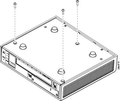
To remove the chassis cover, perform the following steps:
Note
Removing the chassis cover does not affect Cisco warranty. Upgrading the adaptive security appliance does not require any special tools and does not create any radio frequency leaks.
Step 1
Read the Regulatory Compliance and Safety Information for the Cisco ASA 5500 Series document.
Step 2
Power off the adaptive security appliance.
Warning
Before working on a system that has an On/Off switch, turn OFF the power and unplug the power cord. Statement 1
Step 3
Turn the chassis upside down so that the top of the chassis is resting on a flat surface, and the front of the chassis is facing toward you.
Step 4
Remove the three screws located on the bottom of the chassis as shown in Figure 4-1.
Figure 4-1 Removing the Screws
Step 5
Return the chassis to the upright position. Note that the chassis is comprised of two sections: top and bottom.
Step 6
Hold both sides of the top section, at the base of the appliance in the rear and pull outward while gently lifting upward.
Replacing the Chassis Cover
Caution 
Do not operate the adaptive security appliance without the chassis cover installed. The chassis cover protects the internal components, prevents electrical shorts, and provides proper air-flow for cooling the electronic components.
To replace the chassis cover on the adaptive security appliance, perform the following steps:
Step 1
Place the chassis on a secure surface with the front panel facing you.
Step 2
Hold the chassis cover so that the rear of the chassis cover are aligned with the chassis bottom.
Step 3
Lower the front of the cover onto the chassis, making sure that the side tabs of the cover fit under the side panels of the chassis.
Step 4
Slide the chassis cover toward the front, making sure that the cover tabs fit under the back panel, and the back panel tabs fit under the chassis cover.
Step 5
Secure the chassis cover with the screw you set aside earlier.
Step 6
Reconnect the network interface cables.
Step 7
Reconnect the power cord to the power outlet to power on the adaptive security appliance.
Replacing the Lithium Battery
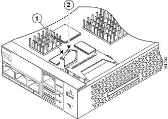
This section describes how to remove and replace the lithium battery in the adaptive security appliance. The lithium battery is a field-replaceable unit (FRU).
Warning
Danger of explosion exists if the lithium battery is incorrectly replaced. Replace only with the same or equivalent type recommended by the manufacturer. Dispose of used batteries according to the manufacturer's instructions. Statement 33
To remove and replace the battery in the adaptive security appliance, perform the following steps:
Step 1
Remove the chassis cover as described in the "Removing the Chassis Cover" section.
Step 2
Slide the metal clip back and pull the battery out.
Figure 4-2 Cisco ASA 5505 Lithium Battery Location
Step 3
Place the used battery aside.
Step 4
Replace the battery with a compactible Lithium CR-2032 battery (which is available at your local electronics or drug store), by sliding the metal clip back and sliding the battery into place.
Step 5
Replace the chassis cover as described in the "Replacing the Chassis Cover" section.
Installing and Replacing the SSC
This section describes how to install and replace the Security Services Card (SSC) . This section includes the following topics:
•
Installing an SSC
•
Replacing an SSC
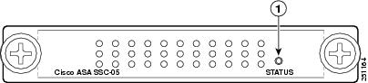
Figure 4-3 lists the SSC LEDs.
Figure 4-3 SSC LEDs
Table 4-1 describes the SSC LEDs.
Table 4-1 SSC LEDs
|
LED
|
Color
|
State
|
Description
|
1
|
STATUS
|
Green
|
Flashing
Solid
|
The system is booting.
The system has passed power-up diagnostics.
|
Installing an SSC
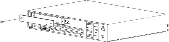
To install a new SSC for the first time, perform the following steps:
Step 1
Power off the adaptive security appliance.
Step 2
Locate the grounding strap from the accessory kit and fasten it to your wrist so that it contacts your bare skin. Attach the other end to the chassis.
Step 3
Remove the two screws (as shown in Figure 4-4) at the left rear end of the chassis, and remove the slot cover.
Figure 4-4 Removing the Screws from the Slot Cover
Step 4
Insert the SSC into the slot opening as shown in Figure 4-5.
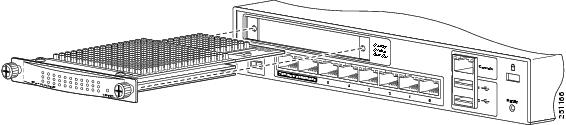
Figure 4-5 Inserting the SSC into the Slot
Step 5
Attach the screws to secure the SSC to the chassis.
Step 6
Power on the adaptive security appliance.
Step 7
Check the LEDs. If the SSC is installed properly the STATUS LED flashes green.
Step 8
Connect one end of the RJ-45 cable to the port and the other end of the cable to your network devices.
Replacing an SSC
To replace an existing SSC, perform the following steps:
Step 1
Enter the hw-mod mod 1 shut command in privileged EXEC mode. Verify if the module is down by checking the LEDs.
Step 2
Locate the grounding strap from the accessory kit and fasten it to your wrist so that it contacts your bare skin. Attach the other end to the chassis.
Step 3
Remove the two screws (as shown in Figure 4-4) at the left rear end of the chassis.
Step 4
Remove the SSC. Set it aside.
Step 5
Replace the existing card by inserting the new SSC through the slot opening as shown in Figure 4-5.
Step 6
Attach the screws to secure the SSC to the chassis.
Step 7
Enter the hw-mod mod 1 reset command in privileged EXEC mode to reset the SSC.
Step 8
Check the LEDs. If the SSC is installed properly, the STATUS LED flashes green.
Step 9
Connect one end of the RJ-45 cable to the port and the other end of the cable to your network devices.
Upgrading Memory
The memory upgrade kit, ASA5505-MEM-512=, allows you to upgrade the Cisco ASA 5505 to 512 MB of memory. To determine how much memory your adaptive security appliance has, use the show version command:
Cisco Adaptive Security Appliance Software Version 8.0(0)
Device Manager Version 6.0(0)
Compiled on Mon 16-April-07 03:29 by root
System image file is "disk0:/cdisk.bin"
Config file at boot was "disk0:/main_backup.cfg"
hostname up 2 days 10 hours
failover cluster up 2 days 11 hours
Hardware: ASA5505, 256 MB RAM, CPU Pentium 4 Celeron 2000 MHz
BIOS Flash M50FW016 @ 0xffe00000, 2048KB
Table 2 lists the memory for the Cisco ASA 5505.
Table 2 Memory Upgrade
Model
|
Current Memory
|
Upgrade to
|
Cisco ASA 5505
|
256 MB
|
512 MB
|
This section describes how to remove and install the memory module on the adaptive security appliance. This section includes the following topics:
•
Removing the DIMM
•
Installing the DIMM
Removing the DIMM
To remove the memory module, perform the following steps:
Step 1
Determine the location of the memory sockets, see Figure 6.
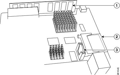
Figure 6 System Memory Location in the Cisco ASA 5505
1
|
DIMM
|
2
|
CompactFlash
|
3
|
Battery
|
Step 2
Locate the wrist grounding strap and connect one end to the adaptive security appliance, and securely attach the other to your wrist so it contacts your bare skin. See, "Working in an ESD Environment" for more information.
Note
Handle the edges of the DIMM only; avoid touching the memory modules, pins, or traces (the metal fingers along the connector edge of the DIMM), along the connector edge.
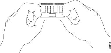
To prevent ESD damage, handle DIMMs as shown in Figure 7.
Figure 7 Handling a DIMM
Step 3
Pull the latches away from the DIMM at both ends. See Figure 8.
Step 4
When both ends of the DIMM are released from the socket, grasp the ends of the DIMM with your thumb and forefinger and pull the DIMM completely out of the socket.
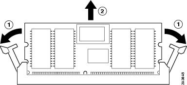
Figure 8 Releasing the DIMM Latches
Step 5
Place the DIMM in an antistatic container to protect it from ESD damage.
Installing the DIMM
To install the memory module, perform the following steps:
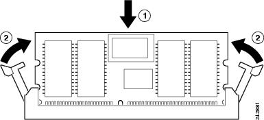
Step 1
Make sure that both latches on the DIMM connector are open.
Step 2
Remove a new DIMM from the antistatic container.
The DIMM is designed in such a way that the connector will fit only one way.
Step 3
Hold the DIMM component side up, with the connector edge away from you. Line up the notch in the connector traces with the notch in the socket on the board.
Step 4
Carefully insert the connector edge into the socket and firmly press the DIMM into the socket until both latches rotate to the close position against the DIMM. See Figure 9.
Figure 9 Inserting the DIMM
Caution 
When inserting DIMMs, use firm but not excessive pressure. You can cause damage to the socket.
When you finish installing new memory, replace the chassis cover.
Verifying the Memory Upgrade
You can verify that the memory upgrade has been completed successfully by entering the show version command:
Cisco Adaptive Security Appliance Software Version 8.0(0)
Device Manager Version 6.0(0)
Compiled on Mon 16-April-07 03:29 by root
System image file is "disk0:/cdisk.bin"
Config file at boot was "disk0:/main_backup.cfg"
hostname up 2 days 10 hours
failover cluster up 2 days 11 hours
Hardware: ASA5505, 512 MB RAM, CPU Pentium 4 Celeron 2000 MHz
BIOS Flash M50FW016 @ 0xffe00000, 2048KB