-
Cisco Security Appliance Command Line Configuration Guide, Version 7.0
-
About This Guide
-
Introduction to the Security Appliance
-
Getting Started
-
Enabling Multiple Context Mode
-
Configuring Ethernet Settings and Subinterfaces
-
Adding and Managing Security Contexts
-
Configuring Interface Parameters
-
Configuring Basic Settings
-
Configuring IP Routing and DHCP Services
-
Configuring IPv6
-
Configuring AAA Servers and the Local Database
-
Configuring Failover
-
Firewall Mode Overview
-
Identifying Traffic With Access Lists
-
Applying NAT
-
Permitting or Denying Network Access
-
Applying AAA for Network Access
-
Applying Filtering Services
-
Using Modular Policy Framework
-
Intercepting and Responding to Network Attacks
-
Applying QoS Policies
-
Applying Application Layer Protocol Inspection
-
Configuring ARP Inspection and Bridging Parameters
-
Configuring IPSec and ISAKMP
-
Setting General VPN Parameters
-
Configuring Tunnel Groups, Group Policies, and Users
-
Configuring IP Addresses for VPN
-
Configuring Remote Access VPNs
-
Configuring LAN-to-LAN VPNs
-
Configuring WebVPN
-
Configuring Certificates
-
Managing System Access
-
Managing Software, Licenses, and Configurations
-
Monitoring and Troubleshooting
-
Feature Licenses and Specifications
-
Sample Configurations
-
Using the Command-Line Interface
-
Addresses, Protocols, and Ports
-
Glossary
-
 Feedback
Table Of Contents
Applying Application Layer Protocol Inspection
Application Inspection Engines
Applying Application Inspection to Selected Traffic
Identifying Traffic with a Traffic Class Map
Using an Application Inspection Map
Defining Actions with a Policy Map
Applying a Security Policy to an Interface
Enabling and Configuring CTIQBE Inspection
Verifying and Monitoring CTIQBE Inspection
How DNS Application Inspection Works
Using the Alias Command for DNS Rewrite
Using the Static Command for DNS Rewrite
DNS Rewrite with Three NAT Zones
Configuring DNS Rewrite with Three NAT Zones
Verifying and Monitoring DNS Inspection
Verifying and Monitoring FTP Inspection
Enabling and Configuring GTP Inspection
Enabling and Configuring GSN Pooling
Verifying and Monitoring GTP Inspection
Enabling and Configuring H.323 Inspection
Configuring H.225 Timeout Values
Verifying and Monitoring H.323 Inspection
Enabling and Configuring Advanced HTTP Inspection
Managing IPSec Pass Through Inspection
IPSec Pass Through Inspection Overview
Enabling and Configuring IPSec Pass Through Inspection
Configuring MGCP Call Agents and Gateways
Configuring and Enabling MGCP Inspection
Configuring MGCP Timeout Values
Verifying and Monitoring MGCP Inspection
Enabling and Configuring SIP Inspection
Configuring SIP Timeout Values
Verifying and Monitoring SIP Inspection
Managing Skinny (SCCP) Inspection
Verifying and Monitoring SCCP Inspection
Managing SMTP and Extended SMTP Inspection
SMTP and Extended SMTP Inspection Overview
Enabling and Configuring SMTP and Extended SMTP Application Inspection
Enabling and Configuring SNMP Application Inspection
Enabling and Configuring Sun RPC Inspection
Verifying and Monitoring Sun RPC Inspection
Applying Application Layer Protocol Inspection
This chapter describes how to use and configure application inspection. This chapter includes the following sections:
•
Application Inspection Engines
•
•
•
•
Application Inspection Engines
This section describes how application inspection engines work. This section includes the following topics:
Overview
The Adaptive Security Algorithm, used by the security appliance for stateful application inspection, ensures the secure use of applications and services. Some applications require special handling by the security appliance and specific application inspection engines are provided for this purpose. Applications that require special application inspection engines are those that embed IP addressing information in the user data packet or open secondary channels on dynamically assigned ports.
Application inspection engines work with NAT to help identify the location of embedded addressing information. This allows NAT to translate these embedded addresses and to update any checksum or other fields that are affected by the translation.
Each application inspection engine also monitors sessions to determine the port numbers for secondary channels. Many protocols open secondary TCP or UDP ports to improve performance. The initial session on a well-known port is used to negotiate dynamically assigned port numbers. The application inspection engine monitors these sessions, identifies the dynamic port assignments, and permits data exchange on these ports for the duration of the specific session.
Note
How Inspection Engines Work
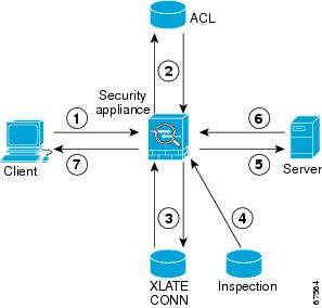
As illustrated in Figure 21-1, the security appliance uses three databases for its basic operation:
•
•
•
Figure 21-1 Basic Adaptive Security Algorithm Operations
In Figure 21-1, operations are numbered in the order they occur, and are described as follows:
1.
2.
3.
4.
5.
6.
7.
The default configuration of the security appliance includes a set of application inspection entries that associate supported protocols with specific TCP or UDP port numbers and that identify any special handling required. For certain applications some inspection engines do not support NAT or PAT because of the constraints imposed by the applications. You can change the port assignments for some applications, while other applications have fixed port assignments that you cannot change. Table 21-1 summarizes this information about the application inspection engines provided with the security appliance.
Supported Protocols
Table 21-1 summarizes the type of application inspections that is provided for each protocol supported by the security appliance. The following inspection engines are described in this chapter:
•
•
•
•
•
•
•
•
•
•
•
•
•
For more information about the inspection engines that are not discussed in this chapter, see the appropriate inspect command pages in the Cisco Security Appliance Command Reference.
Applying Application Inspection to Selected Traffic
This section describes how to identify traffic to which you want to apply an inspection engine, how to associate the inspection engine with a particular security policy, and how to apply the policy to one or more interfaces on the security appliance. This section includes the following topics:
•
•
•
•
Overview
Application inspection is enabled by default for many protocols, while it is disabled for other protocols. In most cases, you can change the port on which the application inspection listens for traffic. To change the default configuration for application inspection for any application inspection engine, use the Modular Policy Framework CLI.
Modular Policy Framework provides a consistent and flexible way to configure security appliance features in a manner to similar to Cisco IOS software Modular Quality of Server (QoS) CLI.
To use Modular Policy Framework to enable application inspection, perform the following steps:
Step 1
A traffic class is a set of traffic that is identifiable by its packet content. You only need to perform this step if you want to change the default port assignments for application inspection or identify traffic to be subjected to application inspection using other criteria, such as the IP address. For a list of default port assignments used for application inspection, see Table 21-1.
Step 2
An action is a security feature, such as application inspection, that helps protect information or resources on one or more protected network interfaces. Application inspection for a specific protocol is one type of action that can be applied using Modular Policy Framework.
Step 3
The application inspection map command enables the configuration mode for a specific application inspection engine, from where you can enter the commands required to change the configuration. The supported application inspection map commands include the following:
•
•
•
•
•
For detailed information about the syntax for each of these commands, see the Cisco Security Appliance Command Reference.
Step 4
A security policy associates a previously defined traffic class with a security-related action and applies it to a specific interface.
You can associate more than one traffic class with a single action and more than one action with a specific traffic class. You can associate all interfaces with a traffic class by entering the global option, or multiple interfaces by entering the service-policy command on separate interfaces.
Identifying Traffic with a Traffic Class Map
A traffic class map contains a name and one match command. The match command identifies the traffic included in the traffic class. The name can be any string of alphanumeric characters.
Match commands can include different criteria to define the traffic included in the class map. For example, you can use one or more access lists to identify specific types of traffic. The permit command in an access control entry causes the traffic to be included, while a deny command causes the traffic to be excluded from the traffic class map. For more information about configuring access lists, see Chapter 9, "Identifying Traffic with Access Control Lists," in the Cisco Security Appliance Command Line Configuration Guide.
After a traffic class is applied to an interface, packets received on that interface are compared to the criteria defined by the match commands in the class map.
If the packet matches the specified criteria, it is included in the traffic class and is subjected to any action, such as application inspection, that is associated with that traffic class. Packets that do not match any of the criteria in any traffic class are assigned to the default traffic class.
To define a traffic class map, perform the following steps:
Step 1
hostname(config)# access-list http_acl permit tcp any any eq 80The http_acl access list in this example includes traffic on port 80. To enable traffic on more than one non-contiguous port, enter the access-list command to create an access control entry for each port.
For the complete syntax of the access-list command see the access-list command page in the Cisco Security Appliance Command Reference.
Step 2
hostname(config)# class-map class_map_nameReplace class_map_name with the name of the traffic class, as in the following example:
hostname(config)# class-map http_portWhen you enter the class-map command, the CLI enters the class map configuration mode, and the prompt changes, as in the following example:
hostname(config-cmap)#Step 3
hostname(config-cmap)# match any | access-list acl_ID | {port tcp | udp {eq port_num |
range port_num port_num}}
Use the any option to include all traffic in the traffic class. Use the access-list option to match the criteria defined in a specific access list. Use the port option to identify a specific port number or a range of port numbers.
Note
The following example uses the port option to assign the default port to the current traffic class:
hostname(config-cmap)# match port tcp eq 80The following example uses the access-list option to assign traffic identified by the access control entries in the http_acl access list:
hostname(config-cmap)# match access-list http_aclYou can also enter the match command to identify traffic based on IP precedence, DSCP (QoS) value, RTP port, or tunnel group. For the complete syntax of the match command, see the Cisco Security Appliance Command Reference.
Step 4
hostname(config-cmap)# match default-inspection-trafficThis command overrides any other port assignments made by entering another match command. However, it can be used with another match command that specifies other criteria, such as destination or source IP address. Table 21-2 lists the default port assignments for different protocols.
Step 5
hostname(config-cmap)# exithostname(config)#
Using an Application Inspection Map
Some application inspection engines have configurable parameters that are used to control application inspection. The default value of these parameters may work without modification, but if you need to fine tune control of the application inspection engine, use an application inspection map. The following procedure provides the general steps required to create an application inspection map.
To use an application inspection map, perform the following steps:
Step 1
hostname(config)# application-map application_map_nameReplace application with the type of application inspection. Replace application_map_name with the name of the application inspection map, for example:
hostname(config)# http-map inbound_httpThis example causes the system to enter HTTP map configuration mode and the CLI prompt changes as follows:
hostname(config-http-map)#Step 2
hostname(config-http-map)# ?Http-map configuration commands:content-length Content length range inspectioncontent-type-verification Content type inspectionmax-header-length Maximum header size inspectionmax-uri-length Maximum URI size inspectionno Negate a command or set its defaultsport-misuse Application inspectionrequest-method Request method inspectionstrict-http Strict HTTP inspectiontransfer-encoding Transfer encoding inspectionhostname(config-http-map)# strict-httphostname(config-http-map)#Step 3
hostname(config-http-map)# exithostname(config)#
Defining Actions with a Policy Map
You use a policy map to associate a traffic class map with a specific action, such as application inspection for a particular protocol. To define a policy map, assign a name to the policy with the policy-map command and then list one or more traffic class maps and one or more actions that should be taken on packets that belong to the given traffic class.
Note
To create a policy map by associating an action with a traffic class, perform the following steps:
Step 1
hostname(config)# policy-map policy_map_nameFor example, the following command creates or modifies the sample_policy policy map:
(config)# policy-map sample_policyThe CLI enters the policy map configuration mode and the prompt changes accordingly, as follows:
hostname(config-pmap)#Step 2
hostname(config-pmap)# class class_map_nameFor example, the following command creates the http_port policy map:
hostname(config-pmap)# class http_portThe CLI enters the class map configuration mode and the prompt changes accordingly, as follows:
hostname(config-pmap-c)#Step 3
hostname(config-pmap-c)# inspect protocol application_inspection_mapUse application_inspection_map if you are enabling a protocol that uses an application map for setting configurable parameters. For example, the following command enables HTTP application inspection using the parameters defined using the http_traffic application inspection map.
hostname(config-pmap-c)# inspect http http_trafficStep 4
hostname(config-pmap-c)# exithostname(config-pmap)#Step 5
hostname(config-pmap-c)# exit
Applying a Security Policy to an Interface
After defining the policy map, apply the policy map to one or more interfaces on the security appliance by entering the service-policy command in global configuration mode. You can enter the service-policy command to activate a policy map globally on all the security appliance interfaces or on a specific interface.
For example, the following command enables the sample_policy service policy on the outside interface:
hostname(config)# service-policy sample_policy interface outsideTo enable the sample_policy service policy on all the security appliance interfaces, enter the following command:
hostname(config)# service-policy sample_policy globalManaging CTIQBE Inspection
This section describes how to enable CTIQBE application inspection and change the default port configuration. This section includes the following topics:
•
•
CTIQBE Inspection Overview
The inspect ctiqbe 2748 command enables CTIQBE protocol inspection, which supports NAT, PAT, and bidirectional NAT. This enables Cisco IP SoftPhone and other Cisco TAPI/JTAPI applications to work successfully with Cisco CallManager for call setup across the security appliance.
TAPI and JTAPI are used by many Cisco VoIP applications. CTIQBE is used by Cisco TSP to communicate with Cisco CallManager.
Limitations and Restrictions
The following summarizes limitations that apply when using CTIQBE application inspection:
•
•
•
The following summarizes special considerations when using CTIQBE application inspection in specific scenarios:
•
•
•
Enabling and Configuring CTIQBE Inspection
To enable CTIQBE inspection or change the default port used for receiving CTIQBE traffic, perform the following steps:
Step 1
hostname(config)# class-map class_map_nameReplace class_map_name with the name of the traffic class, For example:
hostname(config)# class-map ctiqbe_portWhen you enter the class-map command, the CLI enters the class map configuration mode, and the prompt changes, as in the following example:
hostname(config-cmap)#Step 2
hostname(config-cmap)# match port tcp eq 2748hostname(config-cmap)# exithostname(config)#To assign a range of continuous ports, enter the range keyword, as in the following example:
hostname(config-cmap)# match port tcp range 2748-2750To assign more than one non-contiguous port for CTIQBE inspection, enter the access-list command and define an access control entry to match each port. Then enter the match command to associate the access lists with the CTIQBE traffic class.
Step 3
hostname(config)# policy-map policy_map_nameReplace policy_map_name with the name of the policy map, as in the following example:
hostname(config)# policy-map sample_policyThe CLI enters the policy map configuration mode and the prompt changes accordingly, as follows:
hostname(config-pmap)#Step 4
hostname(config-pmap)# class class_map_nameFor example, the following command assigns the ctiqbe_port traffic class to the current policy map:
hostname(config-pmap)# class ctiqbe_portThe CLI enters the policy map class configuration mode and the prompt changes accordingly, as follows:
hostname(config-pmap-c)#Step 5
hostname(config-pmap-c)# inspect ctiqbeStep 6
hostname(config-pmap-c)# exithostname(config-pmap)#Step 7
hostname(config-pmap)# exithostname(config)#Step 8
hostname(config)# service-policy policy_map_name [global | interface interface_IDReplace policy_map_name with the policy map you configured in Step 3, and identify all the interfaces with the global option or a specific interface using the name assigned with the nameif command.
For example, the following command applies the sample_policy to the outside interface:
hostname(config)# service-policy sample_policy interface outsideThe following command applies the sample_policy to the all the security appliance interfaces:
hostname(config)# service-policy sample_policy globalExample 21-1 Enabling and Configuring CTIQBE Inspection
You enable the CTIQBE inspection engine as shown in the following example, which creates a class map to match CTIQBE traffic on the default port (2748). The service policy is then applied to the outside interface.
hostname(config)# class-map ctiqbe_porthostname(config-cmap)# match port tcp eq 2748hostname(config-cmap)# exithostname(config)# policy-map sample_policyhostname(config-pmap)# class ctiqbe_porthostname(config-pmap-c)# inspect ctiqbehostname(config-pmap-c)# exithostname(config)# service-policy sample_policy interface outsideTo enable CTIQBE inspection for all interfaces, enter the global parameter in place of interface outside.
Verifying and Monitoring CTIQBE Inspection
The show ctiqbe command displays information regarding the CTIQBE sessions established across the security appliance. It shows information about the media connections allocated by the CTIQBE inspection engine.
The following is sample output from the show ctiqbe command under the following conditions. There is only one active CTIQBE session setup across the security appliance. It is established between an internal CTI device (for example, a Cisco IP SoftPhone) at local address 10.0.0.99 and an external Cisco CallManager at 172.29.1.77, where TCP port 2748 is the Cisco CallManager. The heartbeat interval for the session is 120 seconds.
hostname# # show ctiqbeTotal: 1LOCAL FOREIGN STATE HEARTBEAT---------------------------------------------------------------1 10.0.0.99/1117 172.29.1.77/2748 1 120----------------------------------------------RTP/RTCP: PAT xlates: mapped to 172.29.1.99(1028 - 1029)----------------------------------------------MEDIA: Device ID 27 Call ID 0Foreign 172.29.1.99 (1028 - 1029)Local 172.29.1.88 (26822 - 26823)----------------------------------------------The CTI device has already registered with the CallManager. The device internal address and RTP listening port is PATed to 172.29.1.99 UDP port 1028. Its RTCP listening port is PATed to UDP 1029.
The line beginning with
RTP/RTCP: PAT xlates:appears only if an internal CTI device has registered with an external CallManager and the CTI device address and ports are PATed to that external interface. This line does not appear if the CallManager is located on an internal interface, or if the internal CTI device address and ports are NATed to the same external interface that is used by the CallManager.The output indicates a call has been established between this CTI device and another phone at 172.29.1.88. The RTP and RTCP listening ports of the other phone are UDP 26822 and 26823. The other phone locates on the same interface as the CallManager because the security appliance does not maintain a CTIQBE session record associated with the second phone and CallManager. The active call leg on the CTI device side can be identified with Device ID 27 and Call ID 0.
The following is sample output from the show xlate debug command for these CTIBQE connections:
hostname# show xlate debug3 in use, 3 most usedFlags: D - DNS, d - dump, I - identity, i - inside, n - no random,r - portmap, s - staticTCP PAT from inside:10.0.0.99/1117 to outside:172.29.1.99/1025 flags ri idle 0:00:22 timeout 0:00:30UDP PAT from inside:10.0.0.99/16908 to outside:172.29.1.99/1028 flags ri idle 0:00:00 timeout 0:04:10UDP PAT from inside:10.0.0.99/16909 to outside:172.29.1.99/1029 flags ri idle 0:00:23 timeout 0:04:10The show conn state ctiqbe command displays the status of CTIQBE connections. In the output, the media connections allocated by the CTIQBE inspection engine are denoted by a `C' flag. The following is sample output from the show conn state ctiqbe command:
hostname# show conn state ctiqbe1 in use, 10 most usedhostname# show conn state ctiqbe detail1 in use, 10 most usedFlags: A - awaiting inside ACK to SYN, a - awaiting outside ACK to SYN,B - initial SYN from outside, C - CTIQBE media, D - DNS, d - dump,E - outside back connection, F - outside FIN, f - inside FIN,G - group, g - MGCP, H - H.323, h - H.225.0, I - inbound data,i - incomplete, J - GTP, j - GTP data, k - Skinny media,M - SMTP data, m - SIP media, O - outbound data, P - inside back connection,q - SQL*Net data, R - outside acknowledged FIN,R - UDP RPC, r - inside acknowledged FIN, S - awaiting inside SYN,s - awaiting outside SYN, T - SIP, t - SIP transient, U - upManaging DNS Inspection
This section describes how to manage DNS application inspection. This section includes the following topics:
•
•
How DNS Application Inspection Works
DNS guard tears down the DNS session associated with a DNS query as soon as the DNS reply is forwarded by the security appliance. DNS guard also monitors the message exchange to ensure that the ID of the DNS reply matches the ID of the DNS query.
When DNS inspection is enabled, which it is the default, the security appliance performs the following additional tasks:
•
Note
•
Note
•
•
•
A single connection is created for multiple DNS sessions, as long as they are between the same two hosts, and the sessions have the same 5-tuple (source/destination IP address, source/destination port, and protocol). DNS identification is tracked by app_id, and the idle timer for each app_id runs independently.
Because the app_id expires independently, a legitimate DNS response can only pass through the security appliance within a limited period of time and there is no resource build-up. However, if you enter the show conn command, you will see the idle timer of a DNS connection being reset by a new DNS session. This is due to the nature of the shared DNS connection and is by design.
DNS port redirection can be enabled using the static command, as in the following example:
static (inside,outside) udp x.x.x.x 53 10.1.1.1 8053In this example, the DNS server listens on port 8053 and the security appliance redirects DNS queries on port 53 to port 8053. For this to work with DNS inspection, you must enable DNS inspection on port 8053. For configuration instructions, see the"Configuring DNS Inspection" section.
How DNS Rewrite Works
When DNS inspection is enabled, DNS rewrite provides full support for NAT of DNS messages originating from any interface.
If a client on an inside network requests DNS resolution of an inside address from a DNS server on an outside interface, the DNS A-record is translated correctly. If the DNS inspection engine is disabled, the A-record is not translated.
As long as DNS inspection remains enabled, you can configure DNS rewrite using the alias, static, or nat commands. For details about the configuration required see the "Configuring DNS Rewrite" section.
DNS rewrite performs two functions:
•
•
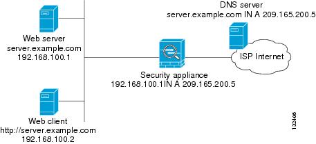
In Figure 21-2, the DNS server resides on the external (ISP) network The real address of the server (192.168.100.1) has been mapped using the static command to the ISP-assigned address (209.165.200.5). A client on any interface can issue an HTTP request to a server. For configuration instructions for this scenario, see the "Configuring DNS Rewrite" section.
Figure 21-2 Translating the Address in a DNS Reply (DNS Rewrite)
A client on any interface can issue a DNS request using "server.example.com." When the DNS request is sent to the external DNS server, the security appliance translates the non-routable source address in the IP header and forwards the request to the ISP network on its outside interface. When the DNS reply is returned, the security appliance applies address translation not only to the destination address, but also to the embedded IP address of the web server, which is contained in the A-record in the DNS reply. As a result, the web client on the inside network gets the correct address for connecting to the web server on the inside network.
DNS rewrite also works if the client making the DNS request is on a DMZ network and the DNS server is on an inside interface. For an illustration and configuration instructions for this scenario, see the "DNS Rewrite with Three NAT Zones" section.
Configuring DNS Rewrite
You configure DNS rewrite using the alias, static, or nat commands. The alias and static command can be used interchangeably. However, Cisco recommends using the static command for new deployments because it is more precise and unambiguous. Also, DNS rewrite is optional when using the static command.
This section describes how to use the alias and static commands to configure DNS rewrite. It provides configuration procedures for using the static command in a simple scenario and in a more complex scenario. Using the nat command is similar to using the static command except that DNS rewrite is based on dynamic translation instead of a static mapping.
This section includes the following topics:
•
•
•
•
For detailed syntax and additional functions for the alias, nat, and static command, see the appropriate command page in the Cisco Security Appliance Command Reference.
Using the Alias Command for DNS Rewrite
The alias command causes addresses on an IP network residing on any interface to be translated into addresses on another IP network connected through a different interface. The syntax for this command is as follows:
hostname(config)# alias (inside) mapped-address real-addressFor example:
hostname(config)# alias (inside) 209.165.200.5 192.168.100.10This command specifies that the real address (192.168.100.10) on any interface except the inside interface will be translated to the mapped address (209.165.200.5) on the inside interface. Note that the location of 192.168.100.10 is not precisely defined.
Note
Using the Static Command for DNS Rewrite
The static command causes addresses on an IP network residing on a specific interface to be translated into addresses on another IP network on a different interface. The syntax for this command is as follows:
hostname(config)# static (inside,outside) mapped-address real-address dnsFor example:
hostname(config)# static (inside,outside) 209.165.200.5 192.168.100.10 dnsThis command specifies that the address 192.168.100.10 on the inside interface is translated into 209.165.200.5 on the outside interface.
Note
Configuring DNS Rewrite
To implement the DNS rewrite scenario shown in Figure 21-2, perform the following steps:
Step 1
hostname(config)# static (inside,outside) 209.165.200.5 192.168.100.1 netmask
255.255.255.255 dns
This command creates a static translation between the web server real address of 192.168.100.1 to the global IP address 209.165.200.5.
Step 2
hostname(config)# access-list 101 permit tcp any host 209.165.200.5 eq wwwhostname(config)# access-group 101 in interface outsideThese commands permit any outside user to access the web server on port 80.
Step 3
DNS application inspection is enabled by default with a maximum DNS packet length of 512 bytes. For configuration instructions, see the "Limitations and Restrictions" section.
Step 4
server.example.com. IN A 209.165.200.5This DNS A-record binds the name server.example.com to the IP address 209.165.200.5.
DNS Rewrite with Three NAT Zones
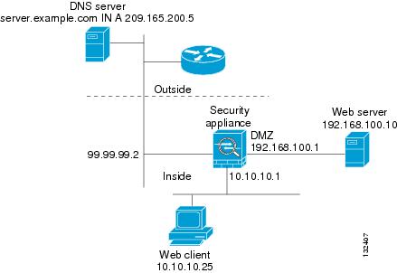
Figure 21-3 provides a more complex scenario to illustrate how DNS inspection allows NAT to operate transparently with a DNS server with minimal configuration. For configuration instructions for this scenario, see the "Configuring DNS Rewrite with Three NAT Zones" section.
Figure 21-3 Configuring DNS Rewrite with Three NAT Zones
In Figure 21-3, a web server, server.example.com, has the real address 192.168.100.10 on the dmz interface of the security appliance. A web client with the IP address 10.10.10.25 is on the inside interface and a public DNS server is on the outside interface. The site NAT policies are as follows:
•
•
•
When a host or client on any interface accesses the DMZ web server, it queries the public DNS server for the A-record of server.example.com. The DNS server returns the A-record showing that server.example.com binds to address 209.165.200.5.
When the request comes from the outside network, the sequence of events is as follows:
1.
2.
3.
When the request comes from the inside network, the sequence of events is as follows:
1.
2.
a.
static (dmz,outside) 209.165.200.5 192.168.100.10 dnsb.
[outside]:209.165.200.5 --> [dmz]:192.168.100.10If the dns option were not included with the static command, DNS rewrite would not be performed and other processing for the packet continues.
c.
No NAT rule is applicable, so application inspection completes.
If a NAT rule (nat or static) were applicable, the dns option must also be specified. If the dns option were not specified, the A-record rewrite in step (b) would be reverted and other processing for the packet continues.
Configuring DNS Rewrite with Three NAT Zones
To enable the NAT policies for the scenario in Figure 21-3, perform the following steps:
Step 1
hostname(config)# static (dmz,outside) 209.165.200.5 192.168.100.10 dnsThis configuration states that hosts on the outside network can access the web server dmz:192.168.100.10 using the address 209.165.200.5. Additionally, the dns option allows the static rule to be used by DNS application inspection to rewrite the DNS A-record.
Step 2
DNS application inspection is enabled by default with a maximum DNS packet length of 512 bytes. For configuration instructions, see the "Limitations and Restrictions" section.
Step 3
hostname(config)# access-list 101 permit tcp any host 209.165.200.5 eq wwwhostname(config)# access-group 101 in interface outsideThese commands permit any outside user to access the web server on port 80.
Step 4
server.example.com. IN A 209.165.200.5This DNS A-record binds the name server.example.com to the IP address 209.165.200.5.
Configuring DNS Inspection
To enable DNS inspection (if it has been previously disabled) or to change the default port used for receiving DNS traffic, perform the following steps:
Step 1
hostname(config)# class-map class_map_nameReplace class_map_name with the name of the traffic class, For example:
hostname(config)# class-map dns_portWhen you enter the class-map command, the CLI enters the class map configuration mode, and the prompt changes, as in the following example:
hostname(config-cmap)#Step 2
hostname(config-cmap)# match port udp eq 8053hostname(config-cmap)# exithostname(config)#Step 3
hostname(config)# policy-map policy_map_nameReplace policy_map_name with the name of the policy map, as in the following example:
hostname(config)# policy-map sample_policyThe CLI enters the policy map configuration mode and the prompt changes accordingly, as follows:
hostname(config-pmap)#Step 4
hostname(config-pmap)# class class_map_nameFor example, the following command assigns the dns_port traffic class to the current policy map:
hostname(config-pmap)# class dns_portThe CLI enters the policy map class configuration mode and the prompt changes accordingly, as follows:
hostname(config-pmap-c)#Step 5
hostname(config-pmap-c)# inspect dns maximum-length [max-pkt-length]To change the maximum DNS packet length from the default (512), replace max-pkt-length with a numeric value. Longer packets will be dropped. To disable checking the DNS packet length, enter the inspect dns command without the maximum-length option.
Step 6
hostname(config-pmap-c)# exithostname(config-pmap)#Step 7
hostname(config-pmap)# exithostname(config)#Step 8
hostname(config)# service-policy policy_map_name [global | interface interface_IDReplace policy_map_name with the policy map you configured in Step 3, and identify all the interfaces with the global option or a specific interface using the name assigned with the nameif command.
For example, the following command applies the sample_policy to the outside interface:
hostname(config)# service-policy sample_policy interface outsideThe following command applies the sample_policy to all the security appliance interfaces:
hostname(config)# service-policy sample_policy globalExample 21-2 Enabling and Configuring DNS Inspection
You enable the DNS inspection engine as shown in the following example, which creates a class map to match DNS traffic on port 8053. The service policy is then applied to the outside interface.
hostname(config)# class-map dns_porthostname(config-cmap)# match port udp eq 8053hostname(config-cmap)# exithostname(config)# policy-map sample_policyhostname(config-pmap)# class dns_porthostname(config-pmap-c)# inspect dns maximum-length 1500hostname(config-pmap-c)# exithostname(config)# service-policy sample_policy interface outsideTo configure DNS inspection for all interfaces, enter the global parameter in place of interface outside.
Verifying and Monitoring DNS Inspection
To view information about the current DNS connections, enter the following command:
hostname# show connFor connections using a DNS server, the source port of the connection may be replaced by the IP address of DNS server in the show conn command output.
A single connection is created for multiple DNS sessions, as long as they are between the same two hosts, and the sessions have the same 5-tuple (source/destination IP address, source/destination port, and protocol). DNS identification is tracked by app_id, and the idle timer for each app_id runs independently.
Because the app_id expires independently, a legitimate DNS response can only pass through the security appliance within a limited period of time and there is no resource build-up. However, when you enter the show conn command, you will see the idle timer of a DNS connection being reset by a new DNS session. This is due to the nature of the shared DNS connection and is by design.
To display the statistics for DNS application inspection, enter the show service-policy command. The following is sample output from the show service-policy command:
hostname# show service-policyInterface outside:Service-policy: sample_policyClass-map: dns_portInspect: dns maximum-length 1500, packet 0, drop 0, reset-drop 0Managing FTP Inspection
This section describes how the FTP inspection engine works and how you can change its configuration. This section includes the following topics:
•
FTP Inspection Overview
The FTP application inspection inspects the FTP sessions and performs four tasks:
•
•
•
•
FTP application inspection prepares secondary channels for FTP data transfer. The channels are allocated in response to a file upload, a file download, or a directory listing event and must be pre-negotiated. The port is negotiated through the PORT or PASV commands.
Note
Using the strict Option
The strict option increases the security of protected networks by preventing web browsers from sending embedded commands in FTP requests.
Note
After enabling the strict option on an interface, an ftp command must be acknowledged before a new command is allowed. Connections sending embedded commands are dropped. The strict option restricts an FTP server to generating the 227 command and restricts the FTP client to generating the PORT command. The 227 and PORT commands are further checked to ensure they do not appear in an error string.
Caution
If the strict option is enabled, each ftp command and response sequence is tracked for the following anomalous activity:
•
•
•
•
•
•
•
•
•
Configuring FTP Inspection
FTP application inspection is enabled default, so you only need to perform the procedures in this section if you want to change the default FTP configuration, in any of the following ways:
•
•
•
To change the default configuration for FTP inspection, perform the following steps:
Step 1
hostname(config)# class-map class_map_nameReplace class_map_name with the name of the traffic class, as in the following example:
hostname(config)# class-map ftp_portWhen you enter the class-map command, the CLI enters the class map configuration mode, and the prompt changes, as in the following example:
hostname(config-cmap)#Step 2
hostname(config-cmap)# match port tcp eq 23hostname(config-cmap)# exithostname(config)#To assign a range of continuous ports, enter the range keyword, as in the following example:
hostname(config-cmap)# match port tcp range 1023-1025To assign more than one non-contiguous port for FTP inspection, enter the access-list command and define an access control entry to match each port. Then enter the match command to associate the access lists with the FTP traffic class.
Step 3
hostname(config)# ftp-map ftp_map_nameReplace ftp_map_name with the name of the FTP map, for example:
hostname(config)# ftp-map inbound_ftpThe system enters FTP map configuration mode and the CLI prompt changes as in the following example:
hostname(config-ftp-map)#Step 4
hostname(config-ftp-map)# request-command deny ftp_commandhostname(config-ftp-map)# exithostname(config)#Replace ftp_command with one or more FTP commands that you want to restrict. See Table 21-3 for a list of the FTP commands that you can restrict. For example, the following command prevents storing or appending files:
hostname(config-inbound_ftp)# request-command deny put stou appe
Note
Step 5
hostname(config)# policy-map policy_map_nameReplace policy_map_name with the name of the policy map, as in the following example:
hostname(config)# policy-map sample_policyThe CLI enters the policy map configuration mode and the prompt changes accordingly, as follows:
hostname(config-pmap)#Step 6
hostname(config-pmap)# class class_map_nameFor example, the following command assigns the ftp_port traffic class to the current policy map.
hostname(config-pmap)# class ftp_portThe CLI enters the policy map class configuration mode and the prompt changes accordingly, as follows:
hostname(config-pmap-c)#Step 7
hostname(config-pmap-c)# inspect strict ftp ftp_map_nameReplace ftp_map_name with the FTP map that you want to use. For example, the following command causes the security appliance to use the FTP map created in the previous steps.
hostname(config-pmap-c)# inspect ftp strict inbound_ftpStep 8
hostname(config-pmap-c)# exithostname(config-pmap)#Step 9
hostname(config-pmap)# exithostname(config)#Step 10
hostname(config)# service-policy policy_map_name [global | interface interface_IDReplace policy_map_name with the policy map you configured in Step 5, and identify all the interfaces with the global option or a specific interface using the name assigned with the nameif command.
For example, the following command applies the sample_policy to the outside interface:
hostname(config)# service-policy sample_policy interface outsideThe following command applies the sample_policy to the all the security appliance interfaces:
hostname(config)# service-policy sample_policy global.
The following complete example shows how to identify FTP traffic, define a FTP map, define a policy, and apply the policy to the outside interface.
Example 21-3 Enabling and Configuring Strict FTP Inspection
hostname(config)# class-map ftp_porthostname(config-cmap)# match port tcp eq 21hostname(config-cmap)# exithostname(config)# ftp-map inbound_ftphostname(config-ftp-map)# request-command deny put stou appehostname(config-ftp-map)# exithostname(config)# policy-map sample_policyhostname(config-pmap)# class ftp_porthostname(config-pmap-c)# inspect ftp strict inbound_ftphostname(config-pmap-c)# exithostname(config-pmap)# exithostname(config)# service-policy sample_policy interface outsideTo enable FTP inspection for all interfaces, enter the global parameter in place of interface outside.
Verifying and Monitoring FTP Inspection
FTP application inspection generates the following log messages:
•
•
•
•
•
In conjunction with NAT, the FTP application inspection translates the IP address within the application payload. This is described in detail in RFC 959.
Managing GTP Inspection
This section describes how the GTP inspection engine works and how you can change its configuration. This section includes the following topics:
•
•
•
Note
GTP Inspection Overview
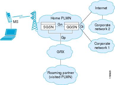
GPRS provides uninterrupted connectivity for mobile subscribers between GSM networks and corporate networks or the Internet. The GGSN is the interface between the GPRS wireless data network and other networks. The SGSN performs mobility, data session management, and data compression (See Figure 21-4).
Figure 21-4 GPRS Tunneling Protocol
The UMTS is the commercial convergence of fixed-line telephony, mobile, Internet and computer technology. UTRAN is the networking protocol used for implementing wireless networks in this system. GTP allows multi-protocol packets to be tunneled through a UMTS/GPRS backbone between a GGSN, an SGSN and the UTRAN.
GTP does not include any inherent security or encryption of user data, but using GTP with the security appliance helps protect your network against these risks.
The SGSN is logically connected to a GGSN using GTP. GTP allows multiprotocol packets to be tunneled through the GPRS backbone between GSNs. GTP provides a tunnel control and management protocol that allows the SGSN to provide GPRS network access for a mobile station by creating, modifying, and deleting tunnels. GTP uses a tunneling mechanism to provide a service for carrying user data packets.
Note
Enabling and Configuring GTP Inspection
GTP application inspection is disabled by default, so you need to complete the procedures described in this section to enable GTP inspection.
Note
To enable or change GTP configuration, perform the following steps:
Step 1
hostname(config)# access-list gtp_acl permit udp any any eq 3386hostname(config)# access-list gtp_acl permit udp any any eq 2123Step 2
hostname(config)# class-map class_map_nameReplace class_map_name with the name of the traffic class, for example:
hostname(config)# class-map gtp_portWhen you enter the class-map command, the CLI enters the class map configuration mode, and the prompt changes, as in the following example:
hostname(config-cmap)#Step 3
hostname(config-cmap)# match access-list gtp_aclhostname(config-cmap)# exithostname(config)#Step 4
hostname(config)# gtp-map gtp_map_nameReplace gtp_map_name with the name of the GTP map, for example:
hostname(config)# gtp-map inbound_gtpThis map is automatically enabled when you enable GTP without specifying a GTP map.
The system enters GTP map configuration mode and the CLI prompt changes as in the following example:
hostname(config-gtp)# gtp-map inbound_gtphostname(config-gtp-map)#Step 5
The default GTP map is used when you enable GTP without specifying a GTP map. This default GTP map is preconfigured with the following default values:
•
•
•
•
•
•
•
Step 6
hostname(config-gtp-map)# exithostname(config)# policy-map policy_map_nameReplace policy_map_name with the name of the policy map, as in the following example:
hostname(config)# policy-map sample_policyThe CLI enters the policy map configuration mode and the prompt changes accordingly, as follows:
hostname(config-pmap)#Step 7
hostname(config-pmap)# class class_map_nameFor example, the following command assigns the gtp_port traffic class to the current policy map:
hostname(config-pmap)# class gtp_portThe CLI enters the policy map class configuration mode and the prompt changes accordingly, as follows:
hostname(config-pmap-c)#Step 8
hostname(config-pmap-c)# inspect gtp [gtp_map_name]The default GTP map is used when you enable GTP without specifying a GTP map. To use a different GTP map, replace gtp_map_name with the GTP map that you want to use. For example, the following command causes the security appliance to use the GTP map created in the previous steps.
hostname(config-pmap-c)# inspect gtp inbound_gtpStep 9
hostname(config-pmap-c)# exithostname(config-pmap)#Step 10
hostname(config-pmap)# exithostname(config)#Step 11
hostname(config)# service-policy policy_map_name [global | interface interface_IDReplace policy_map_name with the policy map you configured in Step 6, and identify all the interfaces with the global option or a specific interface using the name assigned with the nameif command.
For example, the following command applies the sample_policy to the outside interface:
hostname(config)# service-policy sample_policy interface outsideThe following command applies the sample_policy to the all the security appliance interfaces:
hostname(config)# service-policy sample_policy globalThe following example shows how to use access lists to identify GTP traffic, define a GTP map, define a policy, and apply the policy to the outside interface.
Example 21-4 Enabling and Configuring GTP Inspection
hostname(config)# access-list gtp_acl permit udp any any eq 3386hostname(config)# access-list gtp_acl permit udp any any eq 2123hostname(config)# class-map gtp-traffichostname(config-cmap)# match access-list gtp_aclhostname(config-cmap)# exithostname(config)# gtp-map inbound_gtphostname(config-gtp-map)# request-queue 300hostname(config-gtp-map)# mcc 111 mnc 222hostname(config-gtp-map)# message-length min 20 max 300hostname(config-gtp-map)# drop message 20hostname(config-gtp-map)# tunnel-limit 10000hostname(config)# policy-map sample_policyhostname(config-pmap)# class gtp-traffichostname(config-pmap-c)# inspect gtp inbound_gtphostname(config)# service-policy sample_policy outsideTable 21-4 summarizes the configuration commands available in GTP map configuration mode. Refer to the command page in the Cisco Security Appliance Command Reference for the detailed syntax of each command.
Table 21-4 GTP Map Configuration Commands
description
Specifies the GTP configuration map description.
drop
Specifies the message ID, APN, or GTP version to drop.
help
Displays help for GTP map configuration commands.
mcc
Specifies the three-digit mobile country code (000 - 999) and the two or three-digit mobile network code. One or two- digit entries are prepended with 0s.
message-length
Specifies the message length min and max values.
permit errors
Permits packets with errors or different GTP versions.
permit response
Permits GSN load balancing. For more information, see Enabling and Configuring GSN Pooling.
request-queue
Specifies the maximum requests allowed in the queue.
timeout
Specifies the idle timeout for the GSN, PDP context, requests, signaling connections, and tunnels.
tunnel-limit
Specifies the maximum number of tunnels allowed.
Note
Enabling and Configuring GSN Pooling
If the security appliance performs GTP inspection, by default the security appliance drops GTP responses from GSNs that were not specified in the GTP request. This situation occurs when you use load-balancing among a pool of GSNs to provide efficiency and scalability of GPRS.
You can enable support for GSN pooling by using the permit response command. This command configures the security appliance to allow responses from any of a designated set of GSNs, regardless of the GSN to which a GTP request was sent. You identify the pool of load-balancing GSNs as a network object. Likewise, you identify the SGSN as a network object. If the GSN responding belongs to the same object group as the GSN that the GTP request was sent to and if the SGSN is in a object group that the responding GSN is permitted to send a GTP response to, the security appliance permits the response. You add the permit response command to a GTP map configuration, which in turn is specified by the inspect gtp command.
The following procedure provides steps for adding support for GSN pooling to an existing GTP inspection configuration. For more information about configuring GTP inspection, see "Enabling and Configuring GTP Inspection" section.
To enable GSN pooling for an existing GTP inspection configuration, perform the following steps:
Step 1
a.
hostname(config)# object-group network GSN-pool-namehostname(config-network)#For example, the following command creates an object group named gsnpool32:
hostname(config)# object-group network gsnpool32hostname(config-network)#b.
hostname(config-network)# network-object host IP-addressFor example, the following commands create three network objects representing individual hosts:
hostname(config-network)# network-object host 192.168.100.1hostname(config-network)# network-object host 192.168.100.2hostname(config-network)# network-object host 192.168.100.3hostname(config-network)#c.
hostname(config-network)# exithostname(config)#Step 2
a.
hostname(config)# object-group network SGSN-namehostname(config-network)#For example, the following command creates an object group named sgsn32:
hostname(config)# object-group network sgsn32hostname(config-network)#b.
hostname(config-network)# network-object host IP-addressFor example, the following command creates a network objects representing the SGSN:
hostname(config-network)# network-object host 192.168.50.100hostname(config-network)#c.
hostname(config-network)# exithostname(config)#Step 3
hostname(config)# gtp-map GTP-map-namehostname(config-gtp-map)#For example, the following command enters GTP map configuration mode for the GTP map named gtp-policy:
hostname(config)# gtp-map gtp-policyStep 4
hostname(config-gtp-map)# permit response to-object-group SGSN-name from-object-group
GSN-pool-name
For example, the following command permits GTP responses from any host in the object group named gsnpool32 to the host in the object group named sgsn32:
hostname(config-gtp-map)# permit response to-object-group sgsn32 from-object-group
gsnpool32
Example 21-5 shows how to support GSN pooling by defining network objects for the GSN pool and the SGSN. An entire Class C network is defined as the GSN pool but you can identify multiple individual IP addresses, one per network-object command, instead of identifying whole networks. The example then modifies a GTP map to permit responses from the GSN pool to the SGSN.
Example 21-5 Enabling GSN Pooling
hostname(config)# object-group network gsnpool32hostname(config-network)# network-object 192.168.100.0 255.255.255.0hostname(config)# object-group network sgsn32hostname(config-network)# network-object host 192.168.50.100hostname(config-network)# exithostname(config)# gtp-map gtp-policyhostname(config-gtp-map)# permit response to-object-group sgsn32 from-object-group gsnpool32Verifying and Monitoring GTP Inspection
To display GTP configuration, enter the show service-policy inspect gtp command in privileged EXEC mode. For the detailed syntax for this command, see the command page in the Cisco Security Appliance Command Reference.
Use the show service-policy inspect gtp statistics command to show the statistics for GTP inspection. The following is sample output from the show service-policy inspect gtp statistics command:
hostname# show service-policy inspect gtp statisticsGPRS GTP Statistics:version_not_support 0 msg_too_short 0unknown_msg 0 unexpected_sig_msg 0unexpected_data_msg 0 ie_duplicated 0mandatory_ie_missing 0 mandatory_ie_incorrect 0optional_ie_incorrect 0 ie_unknown 0ie_out_of_order 0 ie_unexpected 0total_forwarded 0 total_dropped 0signalling_msg_dropped 0 data_msg_dropped 0signalling_msg_forwarded 0 data_msg_forwarded 0total created_pdp 0 total deleted_pdp 0total created_pdpmcb 0 total deleted_pdpmcb 0pdp_non_existent 0You can use the vertical bar (|) to filter the display. Type ?| for more display filtering options.
Use the show service-policy inspect gtp pdp-context command to display PDP context-related information. The following is sample output from the show service-policy inspect gtp pdp-context command:
hostname# show service-policy inspect gtp pdp-context detail1 in use, 1 most used, timeout 0:00:00Version TID MS Addr SGSN Addr Idle APNv1 1234567890123425 10.0.1.1 10.0.0.2 0:00:13 gprs.cisco.comuser_name (IMSI): 214365870921435 MS address: 1.1.1.1primary pdp: Y nsapi: 2sgsn_addr_signal: 10.0.0.2 sgsn_addr_data: 10.0.0.2ggsn_addr_signal: 10.1.1.1 ggsn_addr_data: 10.1.1.1sgsn control teid: 0x000001d1 sgsn data teid: 0x000001d3ggsn control teid: 0x6306ffa0 ggsn data teid: 0x6305f9fcseq_tpdu_up: 0 seq_tpdu_down: 0signal_sequence: 0upstream_signal_flow: 0 upstream_data_flow: 0downstream_signal_flow: 0 downstream_data_flow: 0RAupdate_flow: 0The PDP context is identified by the tunnel ID, which is a combination of the values for IMSI and NSAPI. A GTP tunnel is defined by two associated PDP contexts in different GSN nodes and is identified with a Tunnel ID. A GTP tunnel is necessary to forward packets between an external packet data network and a MS user.
You can use the vertical bar (|) to filter the display, as in the following example:
hostname# show service-policy gtp statistics | grep gsnManaging H.323 Inspection
This section describes how to enable H.323 application inspection and change the default port configuration. This section includes the following topics:
•
•
•
H.323 Inspection Overview
The inspect h323 command provides support for H.323 compliant applications such as Cisco CallManager and VocalTec Gatekeeper. H.323 is a suite of protocols defined by the International Telecommunication Union for multimedia conferences over LANs. The security appliance supports H.323 through Version 4, including H.323 v3 feature Multiple Calls on One Call Signaling Channel.
With H323 inspection enabled, the security appliance supports multiple calls on the same call signaling channel, a feature introduced with H.323 Version 3. This feature reduces call setup time and reduces the use of ports on the security appliance.
The two major functions of H.323 inspection are as follows:
•
•
How H.323 Works
The H.323 collection of protocols collectively may use up to two TCP connection and four to six UDP connections. FastConnect uses only one TCP connection, and RAS uses a single UDP connection for registration, admissions, and status.
An H.323 client may initially establish a TCP connection to an H.323 server using TCP port 1720 to request Q.931 call setup. As part of the call setup process, the H.323 terminal supplies a port number to the client to use for an H.245 TCP connection. In environments where H.323 gatekeeper is in use, the initial packet is transmitted using UDP.
H.323 inspection monitors the Q.931 TCP connection to determine the H.245 port number. If the H.323 terminals are not using FastConnect, the security appliance dynamically allocates the H.245 connection based on the inspection of the H.225 messages.
Within each H.245 message, the H.323 endpoints exchange port numbers that are used for subsequent UDP data streams. H.323 inspection inspects the H.245 messages to identify these ports and dynamically creates connections for the media exchange. RTP uses the negotiated port number, while RTCP uses the next higher port number.
The H.323 control channel handles H.225 and H.245 and H.323 RAS. H.323 inspection uses the following ports.
•
•
•
You must open an access list for the well-known H.323 port 1720 for the H.225 call signaling. However, the H.245 signaling ports are negotiated between the endpoints in the H.225 signaling. When an H.323 gatekeeper is used, the security appliance opens an H.225 connection based on inspection of the ACF message.
The security appliance dynamically allocates the H.245 channel after inspecting the H.225 messages and then links to the H.245 channel to be fixed up as well. That means whatever H.245 messages pass through the security appliance pass through the H.245 application inspection, NATing embedded IP addresses and opening the negotiated media channels.
The H.323 ITU standard requires that a TPKT header, defining the length of the message, precede the H.225 and H.245, before being passed on to the reliable connection. Because the TPKT header does not necessarily need to be sent in the same TCP packet as the H.225/H.245 message, the security appliance must remember the TPKT length to process/decode the messages properly. The security appliance keeps a data structure for each connection and that data structure contains the TPKT length for the next expected message.
If the security appliance needs to NAT any IP addresses, then it changes the checksum, the UUIE length, and the TPKT, if included in the TCP packet with the H.225 message. If the TPKT is sent in a separate TCP packet, then the security appliance proxy ACKs that TPKT and append a new TPKT to the H.245 message with the new length.
Note
Each UDP connection with a packet going through H.323 inspection is marked as an H.323 connection and times out with the H.323 timeout as configured with the timeout command.
Limitations and Restrictions
The following are some of the known issues and limitations when using H.323 application inspection:
•
•
•
Enabling and Configuring H.323 Inspection
To enable H.323 inspection or change the default port used for receiving H.323 traffic, perform the following steps:
Step 1
hostname(config)# access-list h323_acl permit udp any any eq 1720hostname(config)# access-list h323_acl permit udp any any eq 1721Step 2
hostname(config)# class-map class_map_nameReplace class_map_name with the name of the traffic class, for example:
hostname(config)# class-map h323_portWhen you enter the class-map command, the CLI enters the class map configuration mode, and the prompt changes, as in the following example:
hostname(config-cmap)#In the class map configuration mode, define the match command, as in the following example:
hostname(config-cmap)# match access-list h323_aclhostname(config-cmap)# exithostname(config)#To assign a range of continuous ports, enter the range keyword, as in the following example:
hostname(config-cmap)# match port tcp range 1718-1720To assign more than one non-contiguous port for H323 inspection, enter the access-list command and define an access control entry to match each port. Then enter the match command to associate the access lists with the H323 traffic class.
Step 3
hostname(config)# policy-map policy_map_nameReplace policy_map_name with the name of the policy map, as in the following example:
hostname(config)# policy-map sample_policyThe CLI enters the policy map configuration mode and the prompt changes accordingly, as follows:
hostname(config-pmap)#Step 4
hostname(config-pmap)# class class_map_nameFor example, the following command assigns the h323_port traffic class to the current policy map.
hostname(config-pmap)# class h323_portThe CLI enters the policy map class configuration mode and the prompt changes accordingly, as follows:
hostname(config-pmap-c)#Step 5
hostname(config-pmap-c)# inspect h323 rashostname(config-pmap-c)# inspect h323 h225Return to policy map configuration mode by entering the following command:
hostname(config-pmap-c)# exithostname(config-pmap)#Step 6
hostname(config-pmap)# exithostname(config)#Step 7
hostname(config)# service-policy policy_map_name [global | interface interface_IDReplace policy_map_name with the policy map you configured in Step 3, and identify all the interfaces with the global option or a specific interface using the name assigned with the nameif command.
For example, the following command applies the sample_policy to the outside interface:
hostname(config)# service-policy sample_policy interface outsideThe following command applies the sample_policy to all the security appliance interfaces:
hostname(config)# service-policy sample_policy globalExample 21-6 Enabling and Configuring H.323 Inspection
You enable the H.323 inspection engine as shown in the following example, which creates a class map to match H.323 traffic on the default port (1720). The service policy is then applied to the outside interface.
hostname(config)# access-list h323_acl permit udp any any eq 1720hostname(config)# access-list h323_acl permit udp any any eq 1721hostname(config)# class-map h323-traffichostname(config-cmap)# match access-list h323_aclhostname(config-cmap)# exithostname(config)# policy-map sample_policyhostname(config-pmap)# class h323_porthostname(config-pmap-c)# inspect h323 rashostname(config-pmap-c)# inspect h323 h225hostname(config-pmap-c)# exithostname(config)# service-policy sample_policy interface outsideTo enable H.323 inspection for all interfaces, enter the global parameter in place of interface outside.
Configuring H.225 Timeout Values
To configure the idle time after which an H.225 signalling connection is closed, enter the following command:
hostname(config)# timeout h225The default is 1:00:00.
To configure the idle time after which an H.323 control connection is closed, enter the following command:
hostname(config)# timeout h323The default is 0:05:00.
Verifying and Monitoring H.323 Inspection
This section describes how to display information about H.323 sessions. This section includes the following topics:
•
Monitoring H.225 Sessions
The show h225 command displays information for H.225 sessions established across the security appliance. Along with the debug h323 h225 event, debug h323 h245 event, and show local-host commands, this command is used for troubleshooting H.323 inspection engine issues.
Before entering the show h225, show h245, or show h323-ras commands, we recommend that you configure the pager command. If there are a lot of session records and the pager command is not configured, it may take a while for the show command output to reach its end. If there is an abnormally large number of connections, check that the sessions are timing out based on the default timeout values or the values set by you. If they are not, then there is a problem that needs to be investigated.
The following is sample output from the show h225 command:
hostname# show h225Total H.323 Calls: 11 Concurrent Call(s) forLocal: 10.130.56.3/1040 Foreign: 172.30.254.203/17201. CRV 9861Local: 10.130.56.3/1040 Foreign: 172.30.254.203/17200 Concurrent Call(s) forLocal: 10.130.56.4/1050 Foreign: 172.30.254.205/1720This output indicates that there is currently 1 active H.323 call going through the security appliance between the local endpoint 10.130.56.3 and foreign host 172.30.254.203, and for these particular endpoints, there is 1 concurrent call between them, with a CRV for that call of 9861.
For the local endpoint 10.130.56.4 and foreign host 172.30.254.205, there are 0 concurrent calls. This means that there is no active call between the endpoints even though the H.225 session still exists. This could happen if, at the time of the show h225 command, the call has already ended but the H.225 session has not yet been deleted. Alternately, it could mean that the two endpoints still have a TCP connection opened between them because they set "maintainConnection" to TRUE, so the session is kept open until they set it to FALSE again, or until the session times out based on the H.225 timeout value in your configuration.
Monitoring H.245 Sessions
The show h245 command displays information for H.245 sessions established across the security appliance by endpoints using slow start. Slow start is when the two endpoints of a call open another TCP control channel for H.245. Fast start is where the H.245 messages are exchanged as part of the H.225 messages on the H.225 control channel.) Along with the debug h323 h245 event, debug h323 h225 event, and show local-host commands, this command is used for troubleshooting H.323 inspection engine issues.
The following is sample output from the show h245 command:
hostname# show h245Total: 1LOCAL TPKT FOREIGN TPKT1 10.130.56.3/1041 0 172.30.254.203/1245 0MEDIA: LCN 258 Foreign 172.30.254.203 RTP 49608 RTCP 49609Local 10.130.56.3 RTP 49608 RTCP 49609MEDIA: LCN 259 Foreign 172.30.254.203 RTP 49606 RTCP 49607Local 10.130.56.3 RTP 49606 RTCP 49607There is currently one H.245 control session active across the security appliance. The local endpoint is 10.130.56.3, and we are expecting the next packet from this endpoint to have a TPKT header because the TPKT value is 0. The TKTP header is a 4-byte header preceding each H.225/H.245 message. It gives the length of the message, including the 4-byte header. The foreign host endpoint is 172.30.254.203, and we are expecting the next packet from this endpoint to have a TPKT header because the TPKT value is 0.
The media negotiated between these endpoints have an LCN of 258 with the foreign RTP IP address/port pair of 172.30.254.203/49608 and an RTCP IP address/port of 172.30.254.203/49609 with a local RTP IP address/port pair of 10.130.56.3/49608 and an RTCP port of 49609.
The second LCN of 259 has a foreign RTP IP address/port pair of 172.30.254.203/49606 and an RTCP IP address/port pair of 172.30.254.203/49607 with a local RTP IP address/port pair of 10.130.56.3/49606 and RTCP port of 49607.
Monitoring H.323 RAS Sessions
The show h323-ras command displays information for H.323 RAS sessions established across the security appliance between a gatekeeper and its H.323 endpoint. Along with the debug h323 ras event and show local-host commands, this command is used for troubleshooting H.323 RAS inspection engine issues.
The show h323-ras command displays connection information for troubleshooting H.323 inspection engine issues. The following is sample output from the show h323-ras command:
hostname# show h323-rasTotal: 1GK Caller172.30.254.214 10.130.56.14This output shows that there is one active registration between the gatekeeper 172.30.254.214 and its client 10.130.56.14.
Managing HTTP Inspection
This section describes how the HTTP inspection engine works and how you can change its configuration. This section includes the following topics:
•
HTTP Inspection Overview
Use the inspect http command to protect against specific attacks and other threats that may be associated with HTTP traffic. HTTP inspection performs several functions:
•
•
•
The latter two features are configured in conjunction with the filter command. See the "Applying Filtering" chapter.
Note
The enhanced HTTP inspection feature, which is also known as an application firewall, verifies that HTTP messages conform to RFC 2616, use RFC-defined methods, and comply with various other criteria. This can help prevent attackers from using HTTP messages for circumventing network security policy. In many cases, you can configure these criteria and the way the system responds when these criteria are not met. The actions that you can specify for messages that fail the criteria set using the different configuration commands include allow, reset, or drop. In addition to these actions, you can specify to log the event or not.
The criteria that you can apply to HTTP messages include the following:
•
•
•
•
•
•
•
•
•
•
To enable enhanced HTTP inspection, enter the inspect http http-map command. The rules that this applies to HTTP traffic are defined by the specific HTTP map, which you configure by entering the http-map command and HTTP map configuration mode commands.
Note
Enabling and Configuring Advanced HTTP Inspection
Use the procedures in this section to change the default HTTP configuration, in any of the following ways:
•
•
•
To enable or configure enhanced HTTP inspection, perform the following steps:
Step 1
hostname(config)# class-map class_map_nameReplace class_map_name with the name of the traffic class, for example:
hostname(config)# class-map http_portWhen you enter the class-map command, the CLI enters the class map configuration mode, and the prompt changes, as in the following example:
hostname(config-cmap)#Step 2
hostname(config-cmap)# match port tcp eq 80hostname(config-cmap)# exithostname(config)#To assign a range of continuous ports, enter the range keyword, as in the following example:
hostname(config-cmap)# match port tcp range 1080-1090To assign more than one non-contiguous port for HTTP inspection, enter the access-list command and define an access control entry to match each port. Then enter the match command to associate the access lists with the HTTP traffic class.
Step 3
hostname(config)# http-map http_map_nameReplace http_map_name with the name of the HTTP map, for example:
hostname(config)# http-map inbound_httpThe system enters HTTP map configuration mode and the CLI prompt changes as in the following example:
hostname(config-http-map)#Step 4
Step 5
hostname(config-http-map)# exithostname(config)#Step 6
hostname(config)# policy-map policy_map_nameReplace policy_map_name with the name of the policy map, as in the following example:
hostname(config)# policy-map sample_policyThe CLI enters the policy map configuration mode and the prompt changes accordingly, as follows:
hostname(config-pmap)#Step 7
hostname(config-pmap)# class class_map_nameFor example, the following command assigns the http_port traffic class to the current policy map.
hostname(config-pmap)# class http_portThe CLI enters the policy map class configuration mode and the prompt changes accordingly, as follows:
hostname(config-pmap-c)#Step 8
hostname(config-pmap-c)# inspect http inbound_httpStep 9
hostname(config-pmap-c)# exithostname(config-pmap)#Step 10
hostname(config-pmap)# exithostname(config)#Step 11
hostname(config)# service-policy policy_map_name [global | interface interface_IDReplace policy_map_name with the policy map you configured in Step 6, and identify all the interfaces with the global option or a specific interface using the name assigned with the nameif command.
For example, the following command applies the sample_policy to the outside interface:
hostname(config)# service-policy sample_policy interface outsideThe following command applies the sample_policy to the all the security appliance interfaces:
hostname(config)# service-policy sample_policy globalExample 21-7 Enabling and Configuring Enhanced HTTP Inspection
The following example shows how to use access lists to identify HTTP traffic, define an HTTP map, define a policy, and apply the policy to the outside interface:
hostname(config)# class-map http_porthostname(config-cmap)# match port tcp eq 80hostname(config-cmap)# exithostname(config)# http-map inbound_httphostname(config-http-map)# content-length min 100 max 2000 action reset loghostname(config-http-map)# content-type-verification match-req-rsp reset loghostname(config-http-map)# max-header-length request bytes 100 action log resethostname(config-http-map)# max-uri-length 100 action reset loghostname(config-http-map)# exithostname(config)# policy-map sample_policyhostname(config-pmap)# class http_porthostname(config-pmap-c)# inspect http inbound_httphostname(config-pmap-c)# exithostname(config-pmap)# exithostname(config)# service-policy sample_policy interface outsideTable 21-5 summarizes the configuration commands available in HTTP map configuration mode. Refer to the command page in the Cisco Security Appliance Command Reference for the detailed syntax of each command.
Note
Managing IPSec Pass Through Inspection
This section describes how the HTTP inspection engine works and how you can change its configuration. This section includes the following topics:
•
•
IPSec Pass Through Inspection Overview
The IPSec Pass Through inspection engine lets the security appliance pass ESP (IP protocol 50) traffic that is formed between two hosts because of successful IKE (UDP port 500) negotiation without the requirement of specific ESP access lists.
The inspection engine works on IKE UDP port 500 to create the control flow. The inspect ipsec-pass-thru command is attached to an UDP flow as defined in the MPF framework. When an ESP packet between the two peers arrives at the device, or an UDP packet with either source or destination port equal to 500, the packet is sent to the inspect module.
The ESP traffic is permitted by the inspection engine with the configured idle timeout if there is an existing control flow and it is within the connection limit defined in the MPF framework. A new control flow is created for IKE UDP port 500 traffic with the configured UDP idle timeout if there isn't one, or it uses the existing flow.
To ensure that the packet arrives into the inspection engine, a hole is punched for all such traffic (ESP). This inspect is attached to the control flow. The control flow is present as long as there is at least one data flow (ESP) established, but the traffic always flows on the same connection. Since this IKE connection is kept open as long as data flows, a rekey would always succeed. The flows are created irrespective of NAT or no NAT.
Note
Enabling and Configuring IPSec Pass Through Inspection
Inspect IPSec Pass Through is disabled by default. When enabled without using a parameter map, the inspection uses the default IPSec Pass Through parameter map, which allows only ESP traffic with unlimited connections and the default idle timeout of 10 minutes for the ESP connection.
The following example shows how to define an IPSec Pass Through map:
hostname(config)# access-list test-udp-acl extended permit udp any any eq 500hostname(config)# class-map test-udp-classhostname(config-cmap)# match access-list test-udp-aclhostname(config)# policy-map test-udp-policyhostname(config-pmap)# class test-udp-classhostname(config-pmap-c)# inspect IPSec-pass-thru IPSec-mapThis policy is applied on the interface that has the policy to permit UDP 500 traffic through initially. In this example it is the outside interface.
To verify that the inspection engine opens the ESP data flows for IPSec Pass Through based on the IKE control flow, use the show conn command:
hostname(config)# show connESP out 192.168.51.25 in 192.168.52.50 idle 0:00:00 bytes 864ESP out 192.168.51.25 in 192.168.52.50 idle 0:00:10 bytes 0UDP out 192.168.51.25:500 in 192.168.52.50:500 idle 0:00:00 flags -ESP out 192.168.51.25 in 192.168.52.50 idle 0:00:00 bytes 864ESP out 0.0.0.0 in 0.0.0.0 idle 0:00:10 bytes 0Managing MGCP Inspection
This section describes how to enable and configure MGCP application inspection and change the default port configuration. This section includes the following topics:
•
•
•
•
MGCP Inspection Overview
MGCP is a master/slave protocol used to control media gateways from external call control elements called media gateway controllers or call agents. A media gateway is typically a network element that provides conversion between the audio signals carried on telephone circuits and data packets carried over the Internet or over other packet networks. Using NAT and PAT with MGCP lets you support a large number of devices on an internal network with a limited set of external (global) addresses. Examples of media gateways are:
•
•
•
MGCP messages are transmitted over UDP. A response is sent back to the source address (IP address and UDP port number) of the command, but the response may not arrive from the same address as the command was sent to. This can happen when multiple call agents are being used in a failover configuration and the call agent that received the command has passed control to a backup call agent, which then sends the response. Figure 21-5 illustrates how NAT can be used with MGCP.
Figure 21-5 Using NAT with MGCP
MGCP endpoints are physical or virtual sources and destinations for data. Media gateways contain endpoints on which the call agent can create, modify and delete connections to establish and control media sessions with other multimedia endpoints. Also, the call agent can instruct the endpoints to detect certain events and generate signals. The endpoints automatically communicate changes in service state to the call agent.
MGCP transactions are composed of a command and a mandatory response. There are eight types of commands:
•
•
•
•
•
•
•
•
The first four commands are sent by the call agent to the gateway. The Notify command is sent by the gateway to the call agent. The gateway may also send a DeleteConnection. The registration of the MGCP gateway with the call agent is achieved by the RestartInProgress command. The AuditEndpoint and the AuditConnection commands are sent by the call agent to the gateway.
All commands are composed of a Command header, optionally followed by a session description. All responses are composed of a Response header, optionally followed by a session description.
To use MGCP, you usually need to configure at least two inspect commands: one for the port on which the gateway receives commands, and one for the port on which the call agent receives commands. Normally, a call agent sends commands to the default MGCP port for gateways (2427) while a gateway sends commands to the default MGCP port for call agents (2727).
Configuring MGCP Call Agents and Gateways
Use the call-agent command to specify a group of call agents that can manage one or more gateways. The call agent group information is used to open connections for the call agents in the group (other than the one a gateway sends a command to) so that any of the call agents can send the response. call agents with the same group_id belong to the same group. A call agent may belong to more than one group. The group_id option is a number from 0 to 4294967295. The ip_address option specifies the IP address of the call agent.
To specify a group of call agents, enter the call-agent command in MGCP map configuration mode, which is accessible by entering the mgcp-map command. To remove the configuration, enter the no form of the command.
Use the gateway command to specify which group of call agents are managing a particular gateway. The IP address of the gateway is specified with the ip_address option. The group_id option is a number from 0 to 4294967295 that must correspond with the group_id of the call agents that are managing the gateway. A gateway may only belong to one group.
Note
Configuring and Enabling MGCP Inspection
Use the mgcp-map command to identify a specific map for defining the parameters for MGCP inspection. When you enter this command, the system enters a configuration mode that lets you enter the different commands used for defining the specific map. After defining the MGCP map, you enter the inspect mgcp command to enable the map. You use Modular Policy Framework to apply the inspect command to a defined class of traffic and to apply the policy to a specific interface.
To enable and configure MGCP application inspection, perform the following steps:
Step 1
hostname(config)# access-list mgcp_acl permit udp any any eq 2427hostname(config)# access-list mgcp_acl permit udp any any eq 2727hostname(config)# class-map mgcp-traffichostname(config-cmap)# match access-list mgcp_aclName the traffic class by entering the following command in global configuration mode:
hostname(config)# class-map class_map_nameReplace class_map_name with the name of the traffic class, for example:
hostname(config)# class-map mgcp_portWhen you enter the class-map command, the CLI enters the class map configuration mode, and the prompt changes, as in the following example:
hostname(config-cmap)#Step 2
hostname(config-cmap)# match port udp eq 2427hostname(config-cmap)# exithostname(config)#Step 3
hostname(config)# mgcp-map policy_map_name
Note
Replace mgcp_map_name with the name of the MGCP map, for example:
hostname(config)# mgcp-map inbound_mgcpThe system enters MGCP map configuration mode and the CLI prompt changes as in the following example:
hostname(config-mgcp-map)#Step 4
hostname(config-mgcp-map)# call-agent 10.10.11.5 101hostname(config-mgcp-map)# call-agent 10.10.11.6 101hostname(config-mgcp-map)# call-agent 10.10.11.7 102hostname(config-mgcp-map)# call-agent 10.10.11.8 102Step 5
hostname(config-mgcp-map)# gateway 10.10.10.115 101hostname(config-mgcp-map)# gateway 10.10.10.116 102hostname(config-mgcp-map)# gateway 10.10.10.117 102Step 6
hostname(config-mgcp-map)# command-queue command_limithostname(config-mgcp-map)# exithostname(config)#Step 7
hostname(config)# policy-map policy_map_nameReplace policy_map_name with the name of the policy map, as in the following example:
hostname(config)# policy-map sample_policyThe CLI enters the policy map configuration mode and the prompt changes accordingly, as follows:
hostname(config-pmap)#Step 8
hostname(config-pmap)# class class_map_nameFor example, the following command assigns the mgcp_port traffic class to the current policy map.
hostname(config-pmap)# class mgcp_portThe CLI enters the policy map class configuration mode and the prompt changes accordingly, as follows:
hostname(config-pmap-c)#Step 9
hostname(config-pmap-c)# inspect mgcp inbound_mgcpIf you are not using an MGCP map, enter the following command:
hostname(config-pmap-c)# inspect mgcpStep 10
hostname(config-pmap-c)# exithostname(config-pmap)#Step 11
hostname(config-pmap)# exithostname(config)#Step 12
hostname(config)# service-policy policy_map_name [global | interface interface_IDReplace policy_map_name with the policy map you configured in Step 7, and identify all the interfaces with the global option or a specific interface using the name assigned with the nameif command.
For example, the following command applies the sample_policy to the outside interface:
hostname(config)# service-policy sample_policy interface outsideThe following command applies the sample_policy to the all the security appliance interfaces:
hostname(config)# service-policy sample_policy globalExample 21-6 shows how to identify MGCP traffic, define a MGCP map, define a policy, and apply the policy to the outside interface. This creates a class map to match MGCP traffic on the default ports (2427 and 2727). The service policy is then applied to the outside interface.
Example 21-8 Enabling and Configuring MGCP Inspection
hostname(config)# access-list mgcp_acl permit udp any any eq 2427hostname(config)# access-list mgcp_acl permit udp any any eq 2727hostname(config)# class-map mgcp-traffichostname(config-cmap)# match access-list mgcp_aclhostname(config-cmap)# exithostname(config)# mgcp-map inbound_mgcphostname(config-mgcp-map)# call-agent 10.10.11.5 101hostname(config-mgcp-map)# call-agent 10.10.11.6 101hostname(config-mgcp-map)# call-agent 10.10.11.7 102hostname(config-mgcp-map)# call-agent 10.10.11.8 102hostname(config-mgcp-map)# gateway 10.10.10.115 101hostname(config-mgcp-map)# gateway 10.10.10.116 102hostname(config-mgcp-map)# gateway 10.10.10.117 102hostname(config-mgcp-map)# command-queue 150hostname(config-mgcp-map)# exithostname(config)# policy-map sample_policyhostname(config-pmap)# class mgcp_porthostname(config-pmap-c)# inspect mgcp inbound_mgcphostname(config-pmap-c)# exithostname(config)# service-policy sample_policy interface outsideThis configuration allows call agents 10.10.11.5 and 10.10.11.6 to control gateway 10.10.10.115, and allows call agents 10.10.11.7 and 10.10.11.8 to control both gateways 10.10.10.116 and 10.10.10.117. The maximum number of MGCP commands that can be queued is 150.
To enable MGCP inspection for all interfaces, enter the global parameter in place of interface outside.
Configuring MGCP Timeout Values
The timeout mgcp command lets you set the interval for inactivity after which an MGCP media connection is closed. The default is 5 minutes.
The timeout mgcp-pat command lets you set the timeout for PAT xlates. Because MGCP does not have a keepalive mechanism, if you use non-Cisco MGCP gateways (call agents), the PAT xlates are torn down after the default timeout interval, which is 30 seconds.
Verifying and Monitoring MGCP Inspection
The show mgcp commands command lists the number of MGCP commands in the command queue. The show mgcp sessions command lists the number of existing MGCP sessions. The detail option includes additional information about each command (or session) in the output. The following is sample output from the show mgcp commands command:
hostname# show mgcp commands1 in use, 1 most used, 200 maximum allowedCRCX, gateway IP: host-pc-2, transaction ID: 2052, idle: 0:00:07The following is sample output from the show mgcp detail command.
hostname# show mgcp commands detail1 in use, 1 most used, 200 maximum allowedCRCX, idle: 0:00:10Gateway IP host-pc-2Transaction ID 2052Endpoint name aaln/1Call ID 9876543210abcdefConnection IDMedia IP 192.168.5.7Media port 6058The following is sample output from the show mgcp sessions command.
hostname# show mgcp sessions1 in use, 1 most usedGateway IP host-pc-2, connection ID 6789af54c9, active 0:00:11The following is sample output from the show mgcp sessions detail command.
hostname# show mgcp sessions detail1 in use, 1 most usedSession active 0:00:14Gateway IP host-pc-2Call ID 9876543210abcdefConnection ID 6789af54c9Endpoint name aaln/1Media lcl port 6166Media rmt IP 192.168.5.7Media rmt port 6058Managing RTSP Inspection
This section describes how to enable RTSP application inspection and change the default port configuration. This section includes the following topics:
RTSP Inspection Overview
To configure RTSP application inspection or to change the ports to which the security appliance listens, enter the inspect rtsp command in policy map class configuration mode, which is accessible by entering the class command within policy map configuration mode. To remove the configuration, enter the no form of the command. This command is enabled by default.
The inspect rtsp command lets the security appliance pass RTSP packets. RTSP is used by RealAudio, RealNetworks, Apple QuickTime 4, RealPlayer, and Cisco IP/TV connections.
Note
RTSP applications use the well-known port 554 with TCP (rarely UDP) as a control channel. The security appliance only supports TCP, in conformity with RFC 2326. This TCP control channel is used to negotiate the data channels that is used to transmit audio/video traffic, depending on the transport mode that is configured on the client.
The supported RDT transports are: rtp/avp, rtp/avp/udp, x-real-rdt, x-real-rdt/udp, and x-pn-tng/udp.
The security appliance parses Setup response messages with a status code of 200. If the response message is travelling inbound, the server is outside relative to the security appliance and dynamic channels need to be opened for connections coming inbound from the server. If the response message is outbound, then the security appliance does not need to open dynamic channels.
Because RFC 2326 does not require that the client and server ports must be in the SETUP response message, the security appliance keeps state and remembers the client ports in the SETUP message. QuickTime places the client ports in the SETUP message and then the server responds with only the server ports.
RTSP inspection does not support PAT or dual-NAT. Also, the security appliance cannot recognize HTTP cloaking where RTSP messages are hidden in the HTTP messages.
Using RealPlayer
When using RealPlayer, it is important to properly configure transport mode. For the security appliance, add an access-list command from the server to the client or vice versa. For RealPlayer, change transport mode by clicking Options>Preferences>Transport>RTSP Settings.
If using TCP mode on the RealPlayer, select the Use TCP to Connect to Server and Attempt to use TCP for all content check boxes. On the security appliance, there is no need to configure the inspection engine.
If using UDP mode on the RealPlayer, select the Use TCP to Connect to Server and Attempt to use UDP for static content check boxes, and for live content not available via Multicast. On the security appliance, add an inspect rtsp port command.
Restrictions and Limitations
The following restrictions apply to the inspect rtsp command. The security appliance does not support multicast RTSP or RTSP messages over UDP.
•
•
•
•
•
Configuring RTSP Inspection
To configure RTSP application inspection, perform the following steps:
Step 1
hostname(config)# access-list rtsp_acl permit tcp any any eq 554hostname(config)# access-list rtsp_acl permit tcp any any eq 8554Step 2
hostname(config)# class-map class_map_nameReplace class_map_name with the name of the traffic class, for example:
hostname(config)# class-map rtsp_portWhen you enter the class-map command, the CLI enters the class map configuration mode, and the prompt changes, as in the following example:
hostname(config-cmap)#Step 3
hostname(config-cmap)# match access-list rtsp_aclhostname(config-cmap)# exithostname(config)#Step 4
hostname(config)# policy-map policy_map_nameReplace policy_map_name with the name of the policy map, as in the following example:
hostname(config)# policy-map sample_policyThe CLI enters the policy map configuration mode and the prompt changes accordingly, as follows:
hostname(config-pmap)#Step 5
hostname(config-pmap)# class class_map_nameFor example, the following command assigns the rtsp_port traffic class to the current policy map.
hostname(config-pmap)# class rtsp_portThe CLI enters the policy map class configuration mode and the prompt changes accordingly, as follows:
hostname(config-pmap-c)#Step 6
hostname(config-pmap-c)# inspect rtspStep 7
hostname(config-pmap-c)# exithostname(config-pmap)#Step 8
hostname(config-pmap)# exithostname(config)#Step 9
hostname(config)# service-policy policy_map_name [global | interface interface_IDReplace policy_map_name with the policy map you configured in Step 4, and identify all the interfaces with the global option or a specific interface using the name assigned with the nameif command.
For example, the following command applies the sample_policy to the outside interface:
hostname(config)# service-policy sample_policy interface outsideThe following command applies the sample_policy to all the security appliance interfaces:
hostname(config)# service-policy sample_policy globalExample 21-9 Enabling and Configuring RTSP Inspection
You enable the RTSP inspection engine as shown in the following example, which creates a class map to match RTSP traffic on the default ports (554 and 8554). The service policy is then applied to the outside interface.
hostname(config)# access-list rtsp_acl permit tcp any any eq 554hostname(config)# access-list rtsp_acl permit tcp any any eq 8554hostname(config)# class-map rtsp-traffichostname(config-cmap)# match access-list rtsp_aclhostname(config-cmap)# exithostname(config)# policy-map sample_policyhostname(config-pmap)# class rtsp_porthostname(config-pmap-c)# inspect rtsp 554hostname(config-pmap-c)# inspect rtsp 8554hostname(config-pmap-c)# exithostname(config)# service-policy sample_policy interface outsideTo enable RTSP inspection for all interfaces, enter the global parameter in place of interface outside.
Managing SIP Inspection
This section describes how to enable SIP application inspection and change the default port configuration. This section includes the following topics:
•
•
•
SIP Inspection Overview
SIP, as defined by the IETF, enables call handling sessions, particularly two-party audio conferences, or "calls." SIP works with SDP for call signalling. SDP specifies the ports for the media stream. Using SIP, the security appliance can support any SIP VoIP gateways and VoIP proxy servers. SIP and SDP are defined in the following RFCs:
•
•
To support SIP calls through the security appliance, signaling messages for the media connection addresses, media ports, and embryonic connections for the media must be inspected, because while the signaling is sent over a well-known destination port (UDP/TCP 5060), the media streams are dynamically allocated. Also, SIP embeds IP addresses in the user-data portion of the IP packet. SIP inspection applies NAT for these embedded IP addresses.
The following limitations and restrictions apply when using PAT with SIP:
•
•
•
SIP Instant Messaging
Instant Messaging refers to the transfer of messages between users in near real-time. SIP supports the Chat feature on Windows XP using Windows Messenger RTC Client version 4.7.0105 only. The MESSAGE/INFO methods and 202 Accept response are used to support IM as defined in the following RFCs:
•
•
MESSAGE/INFO requests can come in at any time after registration/subscription. For example, two users can be online at any time, but not chat for hours. Therefore, the SIP inspection engine opens pinholes that time out according to the configured SIP timeout value. This value must be configured at least five minutes longer than the subscription duration. The subscription duration is defined in the Contact Expires value and is typically 30 minutes.
Because MESSAGE/INFO requests are typically sent using a dynamically allocated port other than port 5060, they are required to go through the SIP inspection engine.
Note
SIP inspection NATs the SIP text-based messages, recalculates the content length for the SDP portion of the message, and recalculates the packet length and checksum. It dynamically opens media connections for ports specified in the SDP portion of the SIP message as address/ports on which the endpoint should listen.
SIP inspection has a database with indices CALL_ID/FROM/TO from the SIP payload that identifies the call, as well as the source and destination. Contained within this database are the media addresses and media ports that were contained in the SDP media information fields and the media type. There can be multiple media addresses and ports for a session. RTP/RTCP connections are opened between the two endpoints using these media addresses/ports.
The well-known port 5060 must be used on the initial call setup (INVITE) message. However, subsequent messages may not have this port number. The SIP inspection engine opens signaling connection pinholes, and marks these connections as SIP connections. This is done for the messages to reach the SIP application and be NATed.
As a call is set up, the SIP session is considered in the "transient" state until the media address and media port is received in a Response message from the called endpoint indicating the RTP port the called endpoint listen on. If there is a failure to receive the response messages within one minute, the signaling connection is torn down.
Once the final handshake is made, the call state is moved to active and the signaling connection remains until a BYE message is received.
If an inside endpoint initiates a call to an outside endpoint, a media hole is opened to the outside interface to allow RTP/RTCP UDP packets to flow to the inside endpoint media address and media port specified in the INVITE message from the inside endpoint. Unsolicited RTP/RTCP UDP packets to an inside interface does not traverse the security appliance, unless the security appliance configuration specifically allows it.
Enabling and Configuring SIP Inspection
To enable SIP inspection or change the default port used for receiving SIP traffic, perform the following steps:
Step 1
hostname(config)# class-map class_map_nameReplace class_map_name with the name of the traffic class, for example:
hostname(config)# class-map sip_portWhen you enter the class-map command, the CLI enters the class map configuration mode, and the prompt changes, as in the following example:
hostname(config-cmap)#Step 2
hostname(config-cmap)# match port tcp eq 5060hostname(config-cmap)# exithostname(config)#To assign a range of continuous ports, enter the range keyword, as in the following example:
hostname(config-cmap)# match port tcp range 5060-5070To assign more than one non-contiguous port for SIP inspection, enter the access-list command and define an access control entry to match each port. Then enter the match command to associate the access lists with the SIP traffic class.
Step 3
hostname(config)# policy-map policy_map_nameReplace policy_map_name with the name of the policy map, as in the following example:
hostname(config)# policy-map sample_policyThe CLI enters the policy map configuration mode and the prompt changes accordingly, as follows:
hostname(config-pmap)#Step 4
hostname(config-pmap)# class class_map_nameFor example, the following command assigns the sip_port traffic class to the current policy map.
hostname(config-pmap)# class sip_portThe CLI enters the policy map class configuration mode and the prompt changes accordingly, as follows:
hostname(config-pmap-c)#Step 5
hostname(config-pmap-c)# inspect sipStep 6
hostname(config-pmap-c)# exithostname(config-pmap)#Step 7
hostname(config-pmap)# exithostname(config)#Step 8
hostname(config)# service-policy policy_map_name [global | interface interface_IDReplace policy_map_name with the policy map you configured in Step 3, and identify all the interfaces with the global option or a specific interface using the name assigned with the nameif command.
For example, the following command applies the sample_policy to the outside interface:
hostname(config)# service-policy sample_policy interface outsideThe following command applies the sample_policy to the all the security appliance interfaces:
hostname(config)# service-policy sample_policy globalYou enable the SIP inspection engine as shown in Example 21-8, which creates a class map to match SIP traffic on the default port (5060). The service policy is then applied to the outside interface.
Example 21-10 Enabling SIP Application Inspection
hostname(config)# class-map sip_porthostname(config-cmap)# match port tcp eq 5060hostname(config-cmap)# exithostname(config)# policy-map sample_policyhostname(config-pmap)# class sip_porthostname(config-pmap-c)# inspect sip 5060hostname(config-pmap-c)# exithostname(config)# service-policy sample_policy interface outsideTo enable SIP inspection for all interfaces, enter the global parameter in place of interface outside.
Configuring SIP Timeout Values
The media connections are torn down within two minutes after the connection becomes idle. This is, however, a configurable timeout and can be set for a shorter or longer period of time. To configure the timeout for the SIP control connection, enter the following command:
timeout sipThis command configures the idle timeout after which a SIP control connection is closed.
To configure the timeout for the SIP media connection, enter the following command:
timeout sip_mediaThis command configures the idle timeout after which a SIP media connection is closed.
Verifying and Monitoring SIP Inspection
The show sip command assists in troubleshooting SIP inspection engine issues and is described with the inspect protocol sip udp 5060 command. The show timeout sip command displays the timeout value of the designated protocol.
The show sip command displays information for SIP sessions established across the security appliance. Along with the debug sip and show local-host commands, this command is used for troubleshooting SIP inspection engine issues.
Note
The following is sample output from the show sip command:
hostname# show sipTotal: 2call-id c3943000-960ca-2e43-228f@10.130.56.44state Call init, idle 0:00:01call-id c3943000-860ca-7e1f-11f7@10.130.56.45state Active, idle 0:00:06This sample shows two active SIP sessions on the security appliance (as shown in the Total field). Each call-id
represents a call.The first session, with the call-id c3943000-960ca-2e43-228f@10.130.56.44, is in the state Call Init, which means the session is still in call setup. Call setup is not complete until a final response to the call has been received. For instance, the caller has already sent the INVITE, and maybe received a 100 Response, but has not yet seen the 200 OK, so the call setup is not complete yet. Any non-1xx response message is considered a final response. This session has been idle for 1 second.
The second session is in the state Active, in which call setup is complete and the endpoints are exchanging media. This session has been idle for 6 seconds.
Managing Skinny (SCCP) Inspection
This section describes how to enable SCCP application inspection and change the default port configuration. This section includes the following topics:
•
SCCP Inspection Overview
Skinny (SCCP) is a simplified protocol used in VoIP networks. Cisco IP Phones using SCCP can coexist in an H.323 environment. When used with Cisco CallManager, the SCCP client can interoperate with H.323 compliant terminals. Application layer functions in the security appliance recognize SCCP Version 3.3. The functionality of the application layer software ensures that all SCCP signaling and media packets can traverse the security appliance by providing NAT of the SCCP signaling packets.
There are five versions of the SCCP protocol: 2.4, 3.0.4, 3.1.1, 3.2, and 3.3.2. The security appliance supports all versions through Version 3.3.2. The security appliance provides both PAT and NAT support for SCCP. PAT is necessary if you have limited numbers of global IP addresses for use by IP phones.
Normal traffic between the Cisco CallManager and Cisco IP Phones uses SCCP and is handled by SCCP inspection without any special configuration.The security appliance also supports DHCP options 150 and 66, which allow the security appliance to send the location of a TFTP server to Cisco IP Phones and other DHCP clients. Cisco IP Phones might also include DHCP option 3 in their requests, which sets the default route. For more information, see the "Using Cisco IP Phones with a DHCP Server" section in Chapter 8, "Configuring IP Networking."
Supporting Cisco IP Phones
In topologies where Cisco CallManager is located on the higher security interface with respect to the Cisco IP Phones, if NAT is required for the Cisco CallManager IP address, the mapping must be static because a Cisco IP Phone requires the Cisco CallManager IP address to be specified explicitly in its configuration. An identity static entry allows the Cisco CallManager on the higher security interface to accept registrations from the Cisco IP Phones.
Cisco IP Phones require access to a TFTP server to download the configuration information they need to connect to the Cisco CallManager server.
When the Cisco IP Phones are on a lower security interface compared to the TFTP server, you must use an access list to connect to the protected TFTP server on UDP port 69. While you do need a static entry for the TFTP server, this does not have to be an identity static entry. When using NAT, an identity static entry maps to the same IP address. When using PAT, it maps to the same IP address and port.
When the Cisco IP Phones are on a higher security interface compared to the TFTP server and Cisco CallManager, no access list or static entry is required to allow the Cisco IP Phones to initiate the connection.
Restrictions and Limitations
The following are limitations that apply to the current version of PAT and NAT support for SCCP:
•
•
Note
If the address of an internal Cisco CallManager is configured for NAT or PAT to a different IP address or port, registrations for external Cisco IP Phones fail because the security appliance currently does not support NAT or PAT for the file content transferred over TFTP. Although the security appliance does support NAT of TFTP messages, and opens a pinhole for the TFTP file to traverse the security appliance, the security appliance cannot translate the Cisco CallManager IP address and port embedded in the Cisco IP Phone configuration files that are being transferred using TFTP during phone registration.
To enable SCCP inspection or change the default port used for receiving SCCP traffic, perform the following steps:
Step 1
hostname(config)# class-map class_map_nameReplace class_map_name with the name of the traffic class, for example:
hostname(config)# class-map sccp_portWhen you enter the class-map command, the CLI enters the class map configuration mode, and the prompt changes, as in the following example:
hostname(config-cmap)#Step 2
hostname(config-cmap)# match port tcp eq 2000hostname(config-cmap)# exithostname(config)#To assign a range of continuous ports, enter the range keyword, as in the following example:
hostname(config-cmap)# match port tcp range 2000-2010To assign more than one non-contiguous port for SCCP inspection, enter the access-list command and define an access control entry to match each port. Then enter the match command to associate the access lists with the SCCP traffic class.
Step 3
hostname(config)# policy-map policy_map_nameReplace policy_map_name with the name of the policy map, as in the following example:
hostname(config)# policy-map sample_policyThe CLI enters the policy map configuration mode and the prompt changes accordingly, as follows:
hostname(config-pmap)#Step 4
hostname(config-pmap)# class class_map_nameFor example, the following command assigns the sccp_port traffic class to the current policy map:
hostname(config-pmap)# class sccp_portThe CLI enters the policy map class configuration mode and the prompt changes accordingly, as follows:
hostname(config-pmap-c)#Step 5
hostname(config-pmap-c)# inspect skinnyStep 6
hostname(config-pmap-c)# exithostname(config-pmap)#Step 7
hostname(config-pmap)# exithostname(config)#Step 8
hostname(config)# service-policy policy_map_name [global | interface interface_IDReplace policy_map_name with the policy map you configured in Step 3, and identify all the interfaces with the global option or a specific interface using the name assigned with the nameif command.
For example, the following command applies the sample_policy to the outside interface:
hostname(config)# service-policy sample_policy interface outsideThe following command applies the sample_policy to the all the security appliance interfaces:
hostname(config)# service-policy sample_policy globalYou enable the SCCP inspection engine as shown in Example 21-9, which creates a class map to match SCCP traffic on the default port (2000). The service policy is then applied to the outside interface.
Example 21-11 Enabling SCCP Application Inspection
hostname(config)# class-map sccp_porthostname(config-cmap)# match port tcp eq 2000hostname(config-cmap)# exithostname(config)# policy-map sample_policyhostname(config-pmap)# class sccp_porthostname(config-pmap-c)# inspect skinnyhostname(config-pmap-c)# exithostname(config)# service-policy sample_policy interface outsideVerifying and Monitoring SCCP Inspection
The show skinny command assists in troubleshooting SCCP (Skinny) inspection engine issues. The following is sample output from the show skinny command under the following conditions. There are two active Skinny sessions set up across the security appliance. The first one is established between an internal Cisco IP Phone at local address 10.0.0.11 and an external Cisco CallManager at 172.18.1.33. TCP port 2000 is the CallManager. The second one is established between another internal Cisco IP Phone at local address 10.0.0.22 and the same Cisco CallManager.
hostname# show skinnyLOCAL FOREIGN STATE---------------------------------------------------------------1 10.0.0.11/52238 172.18.1.33/2000 1MEDIA 10.0.0.11/22948 172.18.1.22/207982 10.0.0.22/52232 172.18.1.33/2000 1MEDIA 10.0.0.22/20798 172.18.1.11/22948The output indicates that a call has been established between two internal Cisco IP Phones. The RTP listening ports of the first and second phones are UDP 22948 and 20798 respectively.
The following is sample output from the show xlate debug command for these Skinny connections:
hostname# show xlate debug2 in use, 2 most usedFlags: D - DNS, d - dump, I - identity, i - inside, n - no random,r - portmap, s - staticNAT from inside:10.0.0.11 to outside:172.18.1.11 flags si idle 0:00:16 timeout 0:05:00NAT from inside:10.0.0.22 to outside:172.18.1.22 flags si idle 0:00:14 timeout 0:05:00Managing SMTP and Extended SMTP Inspection
This section describes how to enable SMTP and ESMTP application inspection and change the default port configuration. This section includes the following topics:
•
•
SMTP and Extended SMTP Inspection Overview
ESMTP application inspection provides improved protection against SMTP-based attacks by restricting the types of SMTP commands that can pass through the security appliance and by adding monitoring capabilities.
ESMTP is an enhancement to the SMTP protocol and is similar is most respects to SMTP. For convenience, the term SMTP is used in this document to refer to both SMTP and ESMTP. The application inspection process for extended SMTP is similar to SMTP application inspection and includes support for SMTP sessions. Most commands used in an extended SMTP session are the same as those used in an SMTP session but an ESMTP session is considerably faster and offers more options related to reliability and security, such as delivery status notification.
The inspect esmtp command includes the functionality previously provided by the inspect smtp command, and provides additional support for some extended SMTP commands. Extended SMTP application inspection adds support for eight extended SMTP commands, including AUTH, EHLO, ETRN, HELP, SAML, SEND, SOML and VRFY. Along with the support for seven RFC 821 commands (DATA, HELO, MAIL, NOOP, QUIT, RCPT, RSET), the security appliance supports a total of fifteen SMTP commands.
Other extended SMTP commands, such as ATRN, STARTLS, ONEX, VERB, CHUNKING, and private extensions and are not supported. Unsupported commands are translated into Xs, which are rejected by the internal server. This results in a message such as "500 Command unknown: 'XXX'." Incomplete commands are discarded.
If you enter the inspect smtp command, the security appliance automatically converts the command into the inspect esmtp command, which is the configuration that is shown if you enter the show running-config command.
The inspect esmtp command changes the characters in the server SMTP banner to asterisks except for the "2", "0", "0" characters. Carriage return (CR) and linefeed (LF) characters are ignored.
With SMTP inspection enabled, a Telnet session used for interactive SMTP may hang if the following rules are not observed: SMTP commands must be at least four characters in length; must be terminated with carriage return and line feed; and must wait for a response before issuing the next reply.
An SMTP server responds to client requests with numeric reply codes and optional human-readable strings. SMTP application inspection controls and reduces the commands that the user can use as well as the messages that the server returns. SMTP inspection performs three primary tasks:
•
•
•
SMTP inspection monitors the command and response sequence for the following anomalous signatures:
•
•
•
•
•
•
•
Enabling and Configuring SMTP and Extended SMTP Application Inspection
To enable SMTP and extended SMTP inspection or change the default port used for receiving SMTP traffic, perform the following steps:
Step 1
hostname(config)# class-map class_map_nameReplace class_map_name with the name of the traffic class, for example:
hostname(config)# class-map smtp_portWhen you enter the class-map command, the CLI enters the class map configuration mode, and the prompt changes, as in the following example:
hostname(config-cmap)#Step 2
hostname(config-cmap)# match port tcp eq 25hostname(config-cmap)# exithostname(config)#To assign a range of continuous ports, enter the range keyword, as in the following example:
hostname(config-cmap)# match port tcp range 2025-2030To assign more than one non-contiguous port for SMTP inspection, enter the access-list command and define an access control entry to match each port. Then enter the match command to associate the access lists with the SMTP traffic class.
Step 3
hostname(config)# policy-map policy_map_nameReplace policy_map_name with the name of the policy map, as in the following example:
hostname(config)# policy-map sample_policyThe CLI enters the policy map configuration mode and the prompt changes accordingly, as follows:
hostname(config-pmap)#Step 4
hostname(config-pmap)# class class_map_nameFor example, the following command assigns the smtp_port traffic class to the current policy map.
hostname(config-pmap)# class smtp_portThe CLI enters the policy map class configuration mode and the prompt changes accordingly, as follows:
hostname(config-pmap-c)#Step 5
hostname(config-pmap-c)# inspect esmtpStep 6
hostname(config-pmap-c)# exithostname(config-pmap)#Step 7
hostname(config-pmap)# exithostname(config)#Step 8
hostname(config)# service-policy policy_map_name [global | interface interface_IDReplace policy_map_name with the policy map you configured in Step 3. Identify all the security appliance interfaces with the global option or identify a specific interface using the name assigned with the nameif command.
For example, the following command applies the sample_policy policy map to the outside interface:
hostname(config)# service-policy sample_policy interface outsideThe following command applies the sample_policy policy map to the all the security appliance interfaces:
hostname(config)# service-policy sample_policy globalYou enable the SMTP inspection engine as shown in Example 21-10, which enables SMTP traffic on the default port (25). The service policy is then applied to the outside interface.
Example 21-12 Enabling and Configuring SMTP and ESMTP Inspection
hostname(config)# class-map smtp_porthostname(config-cmap)# match port tcp eq 25hostname(config-cmap)# exithostname(config)# policy-map sample_policyhostname(config-pmap)# class smtp_porthostname(config-pmap-c)# inspect esmtp 25hostname(config-pmap-c)# exithostname(config)# service-policy sample_policy interface outsideTo enable SMTP inspection for all interfaces, enter the global parameter in place of interface outside.
Managing SNMP Inspection
This section describes how to enable SNMP application inspection and change the default port configuration. This section includes the following topics:
•
SNMP Inspection Overview
Use the inspect snmp command to enable SNMP inspection, using the settings configured with an SNMP map, which you create by entering the snmp-map command. Enter the deny version command in SNMP map configuration mode to restrict SNMP traffic to a specific version of SNMP.
Earlier versions of SNMP are less secure, so denying SNMP Version 1 traffic may be required by your security policy. To deny a specific version of SNMP, enter the deny version command within an SNMP map, which you create by entering the snmp-map command. After configuring the SNMP map, you enable the map by entering the inspect snmp command and then apply it to one or more interfaces by entering the service-policy command.
Enabling and Configuring SNMP Application Inspection
To change the default configuration for SNMP inspection, perform the following steps:
Step 1
hostname(config)# access-list snmp_acl permit snmp any any eq 161hostname(config)# access-list snmp_acl permit snmp any any eq 162Step 2
hostname(config)# class-map class_map_nameReplace class_map_name with the name of the traffic class, for example:
hostname(config)# class-map snmp_portWhen you enter the class-map command, the CLI enters the class map configuration mode, and the prompt changes, as in the following example:
hostname(config-cmap)#Step 3
hostname(config-cmap)# match access-list snmp_aclhostname(config-cmap)# exithostname(config)#To assign a range of continuous ports, you can also enter the range keyword, as in the following example:
hostname(config-cmap)# match port snmp range 161-162In this case, you do not need to create access lists for defining the ports on which to enable SNMP application inspection.
Step 4
hostname(config)# snmp-map snmp_map_nameReplace snmp_map_name with the name of the SNMP map, for example:
hostname(config)# snmp-map sample_policyThe system enters SNMP map configuration mode and the CLI prompt changes as in the following example:
hostname(config-snmp-map)#Step 5
hostname(config-snmp-map)# deny version versionReplace version with one or more SNMP versions that you want to restrict, for example:
hostname(config-inbound_ftp)# deny version 1Step 6
hostname(config)# policy-map policy_map_nameReplace policy_map_name with the name of the policy map, as in the following example:
hostname(config)# policy-map sample_policyThe CLI enters the policy map configuration mode and the prompt changes accordingly, as follows:
hostname(config-pmap)#Step 7
hostname(config-pmap)# class class_map_nameFor example, the following command assigns the snmp_port traffic class to the current policy map.
hostname(config-pmap)# class snmp_portThe CLI enters the policy map class configuration mode and the prompt changes accordingly, as follows:
hostname(config-pmap-c)#Step 8
hostname(config-pmap-c)# inspect snmp snmp_map_nameReplace snmp_map_name with the SNMP map that you want to use. For example, the following command causes the security appliance to use the SNMP map created in the previous steps:
hostname(config-pmap-c)# inspect snmp sample_policyStep 9
hostname(config-pmap-c)# exithostname(config-pmap)#Step 10
hostname(config-pmap)# exithostname(config)#Step 11
hostname(config)# service-policy policy_map_name [global | interface interface_IDReplace policy_map_name with the policy map you configured in Step 6, and identify all the interfaces with the global option or a specific interface using the name assigned with the nameif command.
For example, the following command applies the sample_policy to the outside interface:
hostname(config)# service-policy sample_policy interface outsideTo enable strict SNMP application inspection for all interfaces, enter the global parameter in place of interface outside.
The following command applies the sample_policy to the all the security appliance interfaces:
hostname(config)# service-policy sample_policy globalThe following example identifies SNMP traffic, defines an SNMP map, defines a policy, enables SNMP inspection, and applies the policy to the outside interface:
Example 21-13 Configuring SNMP Application Inspection
hostname(config)# access-list snmp_acl permit snmp eq 161hostname(config)# access-list snmp_acl permit snmp eq 162hostname(config)# class-map snmp_porthostname(config-cmap)# match access-list snmp_aclhostname(config-cmap)# exithostname(config)# snmp-map sample_policyhostname(config-snmp-map)# deny version 1hostname(config-snmp-map)# exithostname(config)# policy-map sample_policyhostname(config-pmap)# class snmp_porthostname(config-pmap-c)# inspect snmp sample_policyhostname(config-pmap-c)# exitManaging Sun RPC Inspection
This section describes how to enable Sun RPC application inspection, change the default port configuration, and manage the Sun RPC service table. This section includes the following topics:
•
•
Sun RPC Inspection Overview
To enable Sun RPC application inspection or to change the ports to which the security appliance listens, use the inspect sunrpc command in policy map class configuration mode, which is accessible by using the class command within policy map configuration mode. To remove the configuration, use the no form of this command.
The inspect sunrpc command enables or disables application inspection for the Sun RPC protocol. Sun RPC is used by NFS and NIS. Sun RPC services can run on any port on the system. When a client attempts to access an Sun RPC service on a server, it must find out which port that service is running on. It does this by querying the portmapper process on the well-known port of 111.
The client sends the Sun RPC program number of the service, and gets back the port number. From this point on, the client program sends its Sun RPC queries to that new port. When a server sends out a reply, the security appliance intercepts this packet and opens both embryonic TCP and UDP connections on that port.
Note
Enabling and Configuring Sun RPC Inspection
Note
To enable Sun RPC inspection or change the default port used for receiving Sun RPC traffic using TCP, perform the following steps:
Step 1
hostname(config)# class-map class_map_nameReplace class_map_name with the name of the traffic class, as in the following example:
hostname(config)# class-map sunrpc_portWhen you enter the class-map command, the CLI enters the class map configuration mode, and the prompt changes, as in the following example:
hostname(config-cmap)#Step 2
hostname(config-cmap)# match port tcp eq 111hostname(config-cmap)# exithostname(config)#To assign a range of continuous ports, enter the range keyword, as in the following example:
hostname(config-cmap)# match port tcp range 111-112To assign more than one non-contiguous port for Sun RPC inspection, enter the access-list command and define an access control entry to match each port. Then enter the match command to associate the access lists with the Sun RPC traffic class.
Step 3
hostname(config)# policy-map policy_map_nameReplace policy_map_name with the name of the policy map, as in the following example:
hostname(config)# policy-map sample_policyThe CLI enters the policy map configuration mode and the prompt changes accordingly, as follows:
hostname(config-pmap)#Step 4
hostname(config-pmap)# class class_map_nameFor example, the following command assigns the sunrpc_port traffic class to the current policy map:
hostname(config-pmap)# class sunrpc_portThe CLI enters the policy map class configuration mode and the prompt changes accordingly, as follows:
hostname(config-pmap-c)#Step 5
hostname(config-pmap-c)# inspect sunrpcStep 6
hostname(config-pmap-c)# exithostname(config-pmap)#Step 7
hostname(config-pmap)# exithostname(config)#Step 8
hostname(config)# service-policy policy_map_name [global | interface interface_IDReplace policy_map_name with the policy map you configured in Step 5, and identify all the interfaces with the global option or a specific interface using the name assigned with the nameif command.
For example, the following command applies the sample_policy to the outside interface:
hostname(config)# service-policy sample_policy interface outsideThe following command applies the sample_policy to all the security appliance interfaces:
hostname(config)# service-policy sample_policy globalExample 21-14 Enabling and Configuring Sun RPC Inspection (TCP)
You enable the Sun RPC inspection engine as shown in the following example, which creates a class map to match Sun RPC traffic on TCP port 111. The service policy is then applied to the outside interface.
hostname(config)# class-map sunrpc_porthostname(config-cmap)# match port tcp eq 111hostname(config-cmap)# exithostname(config)# policy-map sample_policyhostname(config-pmap)# class sunrpc_porthostname(config-pmap-c)# inspect sunrpchostname(config-pmap-c)# exithostname(config)# service-policy sample_policy interface outsideTo enable Sun RPC inspection for all interfaces, use the global parameter in place of interface outside.
Example 21-15 Enabling and Configuring Sun RPC Inspection (TCP)
To enable Sun RPC over UDP, simply add the inspect sunrpc command to a policy map whose traffic class is defined by the default traffic class, as shown in the following example:
hostname(config)# policy-map asa_global_fw_policyhostname(config-pmap)# class inspection_defaulthostname(config-pmap-c)# inspect sunrpcManaging Sun RPC Services
Use the Sun RPC services table to control Sun RPC traffic through the security appliance based on established Sun RPC sessions. To create entries in the Sun RPC services table, use the sunrpc-server command in global configuration mode. To remove Sun RPC services table entries from the configuration, use the no form of this command.
You can use this command to specify the timeout after which the pinhole that was opened by Sun RPC application inspection will be closed. For example, to create a timeout of 30 minutes to the Sun RPC server with the IP address 192.168.100.2, enter the following command:
hostname(config)# sunrpc-server inside 192.168.100.2 255.255.255.255 service 100003
protocol tcp 111 timeout 00:30:00
This command specifies that the pinhole that was opened by Sun RPC application inspection will be closed after 30 minutes. In this example, the Sun RPC server is on the inside interface using TCP port 111. You can also specify UDP, a different port number, or a range of ports. To specify a range of ports, separate the starting and ending port numbers in the range with a hyphen (for example, 111-113).
The service type identifies the mapping between a specific service type and the port number used for the service. To determine the service type, which in this example is 100003, use the sunrpcinfo command at the UNIX or Linux command line on the Sun RPC server machine.
To clear the Sun RPC configuration, enter the following command.
hostname(config)# clear configure sunrpc-serverThis removes the configuration performed using the sunrpc-server command. The sunrpc-server command allows pinholes to be created with a specified timeout.
To clear the active Sun RPC services, enter the following command:
hostname(config)# clear sunrpc-server activeThis clears the pinholes that are opened by Sun RPC application inspection for specific services, such as NFS or NIS.
Verifying and Monitoring Sun RPC Inspection
The sample output in this section is for a Sun RPC server with an IP address of 192.168.100.2 on the inside interface and a Sun RPC client with an IP address of 209.168.200.5 on the outside interface.
To view information about the current Sun RPC connections, enter the show conn command. The following is sample output from the show conn command:
hostname# show conn15 in use, 21 most usedUDP out 209.165.200.5:800 in 192.168.100.2:2049 idle 0:00:04 flags -UDP out 209.165.200.5:714 in 192.168.100.2:111 idle 0:00:04 flags -UDP out 209.165.200.5:712 in 192.168.100.2:647 idle 0:00:05 flags -UDP out 192.168.100.2:0 in 209.165.200.5:714 idle 0:00:05 flags ihostname(config)#To display the information about the Sun RPC service table configuration, enter the show running-config sunrpc-server command. The following is sample output from the show running-config sunrpc-server command:
hostname(config)# show running-config sunrpc-serversunrpc-server inside 192.168.100.2 255.255.255.255 service 100003 protocol UDP port 111 timeout 0:30:00sunrpc-server inside 192.168.100.2 255.255.255.255 service 100005 protocol UDP port 111 timeout 0:30:00This output shows that a timeout interval of 30 minutes is configured on UDP port 111 for the Sun RPC server with the IP address 192.168.100.2 on the inside interface.
To display the pinholes open for Sun RPC services, enter the show sunrpc-server active command. The following is sample output from show sunrpc-server active command:
hostname# show sunrpc-server activeLOCAL FOREIGN SERVICE TIMEOUT-----------------------------------------------1 209.165.200.5/0 192.168.100.2/2049 100003 0:30:002 209.165.200.5/0 192.168.100.2/2049 100003 0:30:003 209.165.200.5/0 192.168.100.2/647 100005 0:30:004 209.165.200.5/0 192.168.100.2/650 100005 0:30:00The entry in the LOCAL column shows the IP address of the client or server on the inside interface, while the value in the FOREIGN column shows the IP address of the client or server on the outside interface.
To view information about the Sun RPC services running on a Sun RPC server, enter the rpcinfo -p command from the Linux or UNIX server command line. The following is sample output from the rpcinfo -p command:
sunrpcserver:~ # rpcinfo -pprogram vers proto port100000 2 tcp 111 portmapper100000 2 udp 111 portmapper100024 1 udp 632 status100024 1 tcp 635 status100003 2 udp 2049 nfs100003 3 udp 2049 nfs100003 2 tcp 2049 nfs100003 3 tcp 2049 nfs100021 1 udp 32771 nlockmgr100021 3 udp 32771 nlockmgr100021 4 udp 32771 nlockmgr100021 1 tcp 32852 nlockmgr100021 3 tcp 32852 nlockmgr100021 4 tcp 32852 nlockmgr100005 1 udp 647 mountd100005 1 tcp 650 mountd100005 2 udp 647 mountd100005 2 tcp 650 mountd100005 3 udp 647 mountd100005 3 tcp 650 mountdIn this output, port 647 corresponds to the mountd daemon running over UDP. The mountd process would more commonly be using port 32780. The mountd process running over TCP uses port 650 in this example.