Feedback
Table Of Contents
Cisco Unique Device Identifier Support
Nonstop Forwarding/Stateful Switchover
Verifying the Cisco ASR 9000 Series Router Redundancy
Performing Inventory Management
Determining the ifIndex Value for a Physical Port
Monitoring and Configuring FRU Status
Identifying Hosts to Receive Notifications
Cisco ASR 9000 Series Router QoS Basics
CISCO-CLASS-BASED-QOS-MIB Overview
CISCO-CLASS-BASED-QOS-MIB Object Relationship
QoS Hardware Configuration and Statistic Support
Viewing QoS Configuration Settings Using the CISCO-CLASS-BASED-QOS-MIB
Monitoring QoS Using the CISCO-CLASS-BASED-QOS-MIB
Considerations for Processing QoS Statistics
Checking Customer Interfaces for Service Policies
Retrieving QoS Billing Information
Check the Operational and Administrative Status of Interface
Monitor linkDown and linkUp Notifications
Enabling Interface linkUp and linkDown Notifications
Input and Output Interface Counts
Determining the Amount of Traffic to Bill to a Customer
Scenario for Demonstrating QoS Traffic Policing
Packet Counts Before the Service Policy Is Applied
Packet Counts After the Service Policy Is Applied
Using MIBs
This chapter describes how to work with MIBs on the Cisco ASR 9000 Series router. This appendix contains the following sections:
•
Cisco Unique Device Identifier Support
•
•
Cisco Unique Device Identifier Support
The ENTITY-MIB supports the Cisco compliance effort for a unique device identifier (UDI) standard stored in Identification Programmable Read-Only Memory (IDPROM).
The Cisco UDI provides a unique identity for every Cisco product. The UDI is composed of three separate data elements that must be stored in the entPhysicalTable:
•
•
•
https://tools.cisco.com/emco/inbiz/inbiz/Home
Serial number format is defined in four fields:
–
–
–
–
The SN label is represented as: LLLYYWWSSS.
Note
Cisco Redundancy Features
Redundancy creates a duplication of data elements and software functions to provide an alternative in case of failure. The goal of Cisco redundancy features is to cut over without affecting the link and protocol states associated with each interface and continue packet forwarding. The state of the interfaces and subinterfaces is maintained, along with the state of line cards and various packet processing hardware.
This section describes Cisco redundancy feature:
•
Levels of Redundancy
This section describes the levels of redundancy supported on the Cisco ASR 9000 Series router and how to verify that this feature is available. The Cisco ASR 9000 Series routers supports fault resistance by allowing a Cisco redundant Route Switch Processor (RSP) to take over if the active RSP fails. Redundancy prevents equipment failures from causing service outages, and supports hitless maintenance and upgrade activities. The state of the interfaces and subinterfaces is maintained along with the state of line cards and various packet processing hardware.
Redundant systems support two RSP. One acts as the active RSPs while the other acts as the standby RSPs.
The redundancy feature provides high availability for the Cisco routers by switching when one of the following conditions occur:
•
•
•
The Cisco ASR 9000 Series routers operates in Nonstop Forwarding/Stateful Switchover (NSF/SSO) mode.
Nonstop Forwarding/Stateful Switchover
This section describes the Nonstop Forwarding/Stateful Switchover mode. With NSF/SSO, the Cisco ASR 9000 Series routers can change from the active to the standby RSPs almost immediately while continuing to forward packets. Cisco IOS XR Software NSF/SSO support on this platform enables immediate failover.
In networking devices running NSF/SSO, both RSPs must be running the same configuration so that the standby RSP is always ready to assume control following a fault on the active RSP. The configuration information is synchronized from the active RSP to the standby RSP at startup and each timechanges to the active RSP configuration occur.
Following an initial synchronization between the two RSPs, NFS/SSO maintains RSP state information between them, including forwarding information.
The Cisco Nonstop Forwarding (NSF) works with Stateful Switchover (SSO) to minimize the amount of time a network is unavailable to its users following a Route Switching Processor (RSP) fail-over in a router with dual RSPs. NSF/SSO capability allows routers to detect a switchover and take the necessary actions to continue forwarding network traffic and to recover route information from peer devices.
The Cisco NSF works with the Stateful Switchover (SSO) feature in Cisco IOS XR Software to minimize the amount of time a network is unavailable to its users following a switchover. The main objective of the Cisco NSF/SSO is to continue forwarding data packets along known routes while the routing protocol information is restored following a route switchover.
Verifying the Cisco ASR 9000 Series Router Redundancy
To display information about the active and standby RSP engines installed in the Cisco ASR 9000 Series router, use the show redundancy command and show redundancy states command.
ExampleRSP/0/RSP0/CPU0:aus-ASR-9010-18#show redundancyFri Feb 20 01:15:10.213 PST PSTRedundancy information for node 0/RSP0/CPU0:==========================================Node 0/RSP0/CPU0 is in ACTIVE rolePartner node (0/RSP1/CPU0) is in STANDBY roleStandby node in 0/RSP1/CPU0 is readyStandby node in 0/RSP1/CPU0 is NSR-readyReload and boot info----------------------A9K-RSP-4G reloaded Thu Feb 19 09:29:24 2009: 15 hours, 45 minutes agoActive node booted Thu Feb 19 10:40:02 2009: 14 hours, 35 minutes agoLast switch-over Thu Feb 19 21:45:59 2009: 3 hours, 29 minutes agoStandby node boot Thu Feb 19 21:46:57 2009: 3 hours, 28 minutes agoStandby node last went not ready Thu Feb 19 21:49:06 2009: 3 hours, 26 minutes agoStandby node last went ready Thu Feb 19 21:49:06 2009: 3 hours, 26 minutes agoStandby node last went not NSR-ready Thu Feb 19 21:49:27 2009: 3 hours, 25 minutes agoStandby node last went NSR-ready Thu Feb 19 21:49:27 2009: 3 hours, 25 minutes agoThere have been 2 switch-overs since reloadManaging Physical Entities
This section describes how to use SNMP to manage the physical entities (components) in the router by:
•
•
•
Purpose and Benefits
The physical entity management feature of the Cisco ASR 9000 Series router SNMP implementation does the following:
•
•
•
•
MIBs Used for Physical Entity Management
•
•
•
•
–
Each entity is identified by a unique index (entPhysicalIndex) that is used to access information about the entity in this and other MIBs.
–
–
Performing Inventory Management
To obtain information about entities in the router, perform a MIB walk on the ENTITY-MIB entPhysicalTable.
As you examine sample entries in the ENTITY-MIB entPhysicalTable, consider the following objects:
•
•
•
Note
Sample of ENTITY-MIB entPhysicalTable Entries
The samples in this section show how information is stored in the entPhysicalTable. You can perform asset inventory by examining entPhysicalTable entries.
Note
The following display shows the ENTITY-MIB entPhysicalTable sample entries:
entPhysicalDescr.186 = 4-Port 10GE Extended Line Card, Requires XFPsentPhysicalDescr.187 = Ten GigabitEthernet PortentPhysicalDescr.188 = GigeEthernet XFP containerentPhysicalDescr.189 =entPhysicalDescr.190 = Transceiver Temperature SensorentPhysicalDescr.191 = Transceiver Tx Power SensorentPhysicalDescr.192 = Transceiver Rx Power SensorentPhysicalDescr.193 = Transceiver Transmit Bias Current SensorentPhysicalDescr.194 = Line Card hostentPhysicalDescr.195 = Inlet Temperature SensorentPhysicalDescr.196 = Hot Temperature SensorentPhysicalDescr.197 = Voltage Sensor - IBVentPhysicalDescr.198 = Voltage Sensor - 5.0VentPhysicalDescr.199 = Voltage Sensor - VP3P3_CANentPhysicalDescr.200 = Voltage Sensor - 3.3VWhere entPhysicalDescr identifies the manufacturer name for the physical entity.
entPhysicalVendorType.186 = cevModuleA9K4x10GEEentPhysicalVendorType.187 = cevPortGEXFPentPhysicalVendorType.188 = cevContainerXFPentPhysicalVendorType.189 = cevXFPUnknownentPhysicalVendorType.190 = cevSensorTransceiverTempentPhysicalVendorType.191 = cevSensorTransceiverTxPwrentPhysicalVendorType.192 = cevSensorTransceiverRxPwrentPhysicalVendorType.193 = cevSensorTransceiverCurrententPhysicalVendorType.194 = cevModuleASR9KHostentPhysicalVendorType.195 = cevSensorModuleInletTempentPhysicalVendorType.196 = cevSensorHotTemperatureentPhysicalVendorType.197 = cevSensorModuleDeviceVoltageentPhysicalVendorType.198 = cevSensorModuleDeviceVoltageentPhysicalVendorType.199 = cevSensorModuleDeviceVoltageentPhysicalVendorType.200 = cevSensorModuleDeviceVoltageWhere entPhysicalVendorType identifies the unique vendor-specific hardware type of the physical entity.
entPhysicalContainedIn.186 = 92entPhysicalContainedIn.187 = 186entPhysicalContainedIn.188 = 187entPhysicalContainedIn.189 = 188entPhysicalContainedIn.190 = 189entPhysicalContainedIn.191 = 189entPhysicalContainedIn.192 = 189entPhysicalContainedIn.193 = 189entPhysicalContainedIn.194 = 186entPhysicalContainedIn.195 = 194entPhysicalContainedIn.196 = 194entPhysicalContainedIn.197 = 194entPhysicalContainedIn.198 = 194entPhysicalContainedIn.199 = 194entPhysicalContainedIn.200 = 194Where entPhysicalContainedIn indicates the entPhysicalIndex of a parent entity (component).
entPhysicalClass.186 = module(9)entPhysicalClass.187 = port(10)entPhysicalClass.188 = container(5)entPhysicalClass.189 = module(9)entPhysicalClass.190 = sensor(8)entPhysicalClass.191 = sensor(8)entPhysicalClass.192 = sensor(8)entPhysicalClass.193 = sensor(8)entPhysicalClass.194 = module(9)entPhysicalClass.195 = sensor(8)entPhysicalClass.196 = sensor(8)entPhysicalClass.197 = sensor(8)entPhysicalClass.198 = sensor(8)entPhysicalClass.199 = sensor(8)entPhysicalClass.200 = sensor(8)Where entPhysicalClass indicates the general type of hardware device.
entPhysicalParentRelPos.186 = 0entPhysicalParentRelPos.187 = 1entPhysicalParentRelPos.188 = 0entPhysicalParentRelPos.189 = 0entPhysicalParentRelPos.190 = 0entPhysicalParentRelPos.191 = 1entPhysicalParentRelPos.192 = 2entPhysicalParentRelPos.193 = 3entPhysicalParentRelPos.194 = 0entPhysicalParentRelPos.195 = 0entPhysicalParentRelPos.196 = 1entPhysicalParentRelPos.197 = 2entPhysicalParentRelPos.198 = 3entPhysicalParentRelPos.199 = 4entPhysicalParentRelPos.200 = 5Where entPhysicalParentRelPos indicates the relative position of this child among the other entities.
entPhysicalName.186 = module 0/5/CPU0entPhysicalName.187 = TenGigE0/5/0/1entPhysicalName.188 = slot mau 0/5/CPU0/1entPhysicalName.189 = module mau 0/5/CPU0/1entPhysicalName.190 = temperature 0/5/CPU0/1entPhysicalName.191 = power Tx 0/5/CPU0/1entPhysicalName.192 = power Rx 0/5/CPU0/1entPhysicalName.193 = current 0/5/CPU0/1entPhysicalName.194 = module 0/5/CPU0entPhysicalName.195 = temperature 0/5/CPU0entPhysicalName.196 = temperature 0/5/CPU0entPhysicalName.197 = voltage 0/5/CPU0entPhysicalName.198 = voltage 0/5/CPU0entPhysicalName.199 = voltage 0/5/CPU0entPhysicalName.200 = voltage 0/5/CPU0Where entPhysicalName provides the textual name of the physical entity.
entPhysicalHardwareRev.186 =entPhysicalHardwareRev.187 =entPhysicalHardwareRev.188 =entPhysicalHardwareRev.189 =entPhysicalHardwareRev.190 =entPhysicalHardwareRev.191 =entPhysicalHardwareRev.192 =entPhysicalHardwareRev.193 =entPhysicalHardwareRev.194 =entPhysicalHardwareRev.195 =entPhysicalHardwareRev.196 =entPhysicalHardwareRev.197 =entPhysicalHardwareRev.198 =entPhysicalHardwareRev.199 =entPhysicalHardwareRev.200 =Where entPhysicalHardwareRev provides the vendor-specific hardware revision number (string) for the physical entity.
entPhysicalFirmwareRev.186 = Version 0.63(20081010:215422)entPhysicalFirmwareRev.187 =entPhysicalFirmwareRev.188 =entPhysicalFirmwareRev.189 =entPhysicalFirmwareRev.190 =entPhysicalFirmwareRev.191 =entPhysicalFirmwareRev.192 =entPhysicalFirmwareRev.193 =entPhysicalFirmwareRev.194 =entPhysicalFirmwareRev.195 =entPhysicalFirmwareRev.196 =entPhysicalFirmwareRev.197 =entPhysicalFirmwareRev.198 =entPhysicalFirmwareRev.199 =entPhysicalFirmwareRev.200 =Where entPhysicalFirmwareRev provides the vendor-specific firmware revision number (string) for the physical entity.
entPhysicalSoftwareRev.186 = 3.7.2.24IentPhysicalSoftwareRev.187 =entPhysicalSoftwareRev.188 =entPhysicalSoftwareRev.189 = 3.7.2.24IentPhysicalSoftwareRev.190 =entPhysicalSoftwareRev.191 =entPhysicalSoftwareRev.192 =entPhysicalSoftwareRev.193 =entPhysicalSoftwareRev.194 = 3.7.2.24IentPhysicalSoftwareRev.195 =entPhysicalSoftwareRev.196 =entPhysicalSoftwareRev.197 =entPhysicalSoftwareRev.198 =entPhysicalSoftwareRev.199 =entPhysicalSoftwareRev.200 =Where entPhysicalSoftwareRev provides the software revision number for the physical entity.
entPhysicalSerialNum.186 = FHH1213002AentPhysicalSerialNum.187 =entPhysicalSerialNum.188 =entPhysicalSerialNum.189 = ECL114704JDentPhysicalSerialNum.190 =entPhysicalSerialNum.191 =entPhysicalSerialNum.192 =entPhysicalSerialNum.193 =entPhysicalSerialNum.194 =entPhysicalSerialNum.195 =entPhysicalSerialNum.196 =entPhysicalSerialNum.197 =entPhysicalSerialNum.198 =entPhysicalSerialNum.199 =entPhysicalSerialNum.200 =Where entPhysicalSerialNum provides the vendor-specific serial number (string) for the physical entity.
entPhysicalMfgName.186 = Cisco Systems Inc.entPhysicalMfgName.187 =entPhysicalMfgName.188 =entPhysicalMfgName.189 =entPhysicalMfgName.190 =entPhysicalMfgName.191 =entPhysicalMfgName.192 =entPhysicalMfgName.193 =entPhysicalMfgName.194 =entPhysicalMfgName.195 =entPhysicalMfgName.196 =entPhysicalMfgName.197 =entPhysicalMfgName.198 =entPhysicalMfgName.199 =entPhysicalMfgName.200 =Where entPhysicalMfgName provides the manufacturer name for the physical component.
entPhysicalModelName.186 = A9K-4T-EentPhysicalModelName.187 =entPhysicalModelName.188 =entPhysicalModelName.189 = ONS-XC-10G-S1entPhysicalModelName.190 =entPhysicalModelName.191 =entPhysicalModelName.192 =entPhysicalModelName.193 =entPhysicalModelName.194 =entPhysicalModelName.195 =entPhysicalModelName.196 =entPhysicalModelName.197 =entPhysicalModelName.198 =entPhysicalModelName.199 =entPhysicalModelName.200 =Where entPhysicalModelName provides the vendor-specific model name string for the physical component.
entPhysicalAlias.186 =entPhysicalAlias.187 =entPhysicalAlias.188 =entPhysicalAlias.189 =entPhysicalAlias.190 =entPhysicalAlias.191 =entPhysicalAlias.192 =entPhysicalAlias.193 =entPhysicalAlias.194 = hostentPhysicalAlias.195 =entPhysicalAlias.196 =entPhysicalAlias.197 =entPhysicalAlias.198 =entPhysicalAlias.199 =entPhysicalAlias.200 =Where entPhysicalAlias provides the alias name for the physical component.
entPhysicalAssetID.186 =entPhysicalAssetID.187 =entPhysicalAssetID.188 =entPhysicalAssetID.189 =entPhysicalAssetID.190 =entPhysicalAssetID.191 =entPhysicalAssetID.192 =entPhysicalAssetID.193 =entPhysicalAssetID.194 =entPhysicalAssetID.195 =entPhysicalAssetID.196 =entPhysicalAssetID.197 =entPhysicalAssetID.198 =entPhysicalAssetID.199 =entPhysicalAssetID.200 =Where entPhysicalAssetID provides the vendor-specific asset ID for the physical component.
entPhysicalIsFRU.186 = true(1)entPhysicalIsFRU.187 = false(2)entPhysicalIsFRU.188 = false(2)entPhysicalIsFRU.189 = true(1)entPhysicalIsFRU.190 = false(2)entPhysicalIsFRU.191 = false(2)entPhysicalIsFRU.192 = false(2)entPhysicalIsFRU.193 = false(2)entPhysicalIsFRU.194 = false(2)entPhysicalIsFRU.195 = false(2)entPhysicalIsFRU.196 = false(2)entPhysicalIsFRU.197 = false(2)entPhysicalIsFRU.198 = false(2)entPhysicalIsFRU.199 = false(2)entPhysicalIsFRU.200 = false(2)Where entPhysicalIsFRU indicates whether or not this physical entity is considered a field-replaceable unit (FRU).
Note the following about the sample configuration:
•
–
–
•
Determining the ifIndex Value for a Physical Port
The ENTITY-MIB entAliasMappingIdentifier maps a physical port to an interface by mapping the port's entPhysicalIndex to its corresponding ifIndex value in the IF-MIB ifTable. The following sample shows that the physical port with a entPhysicalIndex value of 35 is associated with the interface with the ifIndex value of four:
entAliasMappingIdentifer.35.0 = ifIndex.4
Note
Monitoring and Configuring FRU Status
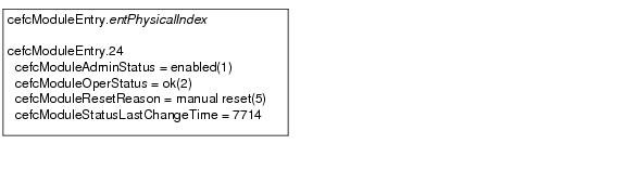
View objects in the CISCO-ENTITY-FRU-CONTROL-MIB cefcModuleTable to determine the administrative and operational status of FRUs, such as power supplies and line cards:
•
•
Figure 5-1 shows a cefcModuleTable entry for a line card with the entPhysicalIndex value of 24.
Figure 5-1 Sample cefcModuleTable Entry
See the "FRU Status Changes" section for information about how the router generates notifications to indicate changes in FRU status.
Generating SNMP Notifications
This section provides information about the SNMP notifications generated in response to events and conditions on the router, and describes how to identify which hosts are to receive notifications.
•
Identifying Hosts to Receive Notifications
You can use the CLI or SNMP to identify hosts to receive SNMP notifications and to specify the types of notifications they are to receive (notifications). For CLI instructions, see the "Enabling Notifications" section. To use SNMP to configure this information:
Use SNMP-NOTIFICATION-MIB objects, including the following, to select target hosts and specify the types of notifications to generate for those hosts:
•
–
–
•
Use SNMP-TARGET-MIB objects to configure information about the hosts to receive notifications:
•
–
•
Use the notification enable objects in appropriate MIBs to enable and disable specific SNMP notifications.
Configuration Changes
If entity notifications are enabled, the router generates an entConfigChange notification (ENTITY-MIB) when the information in any of the following tables changes (which indicates a change to the router configuration):
•
•
•
Note
Enabling Notifications for Configuration Changes
To configure the router to generate an entConfigChange notification each time its configuration changes, enter the snmp-sever trap entity command from the CLI. Use the no form of the command to disable the notifications.
Router(config)# snmp-server traps entityRouter(config)# no snmp-server traps entityFRU Status Changes
If FRU notifications are enabled, the router generates the following notifications in response to changes in the status of a FRU:
•
•
•
Note
Enabling FRU Notifications
To configure the router to generate notifications for FRU events, enter the snmp-server traps fru-ctrl command from the CLI. Use the no form of the command to disable the notifications.
Router(config)# snmp-server traps fru-ctrlRouter(config)# no snmp-server traps fru-ctrlTo enable FRU notifications through SNMP, set cefcMIBEnableStatusNotification to true(1). Disable the notifications by setting cefcMIBEnableStatusNotification to false(2).
Monitoring Quality of Service
This section provides the following information about using Quality of Service (QoS) in your configuration:
•
•
•
•
•
Cisco ASR 9000 Series Router QoS Basics
The Cisco ASR 9000 Series router distributes QoS features across the line cards. Line cards are designed to provide QoS features on packets that flow through the line cards.
CISCO-CLASS-BASED-QOS-MIB Overview
The CISCO-CLASS-BASED-QOS-MIB provides read-only access to Quality of Service (QoS) configuration information and statistics for Cisco platforms that support the modular Quality of Service command-line interface (modular QoS CLI).
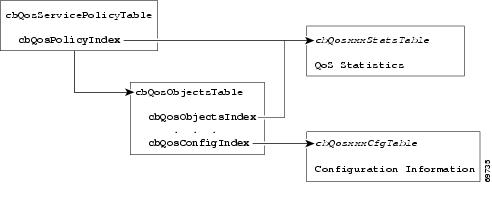
CISCO-CLASS-BASED-QOS-MIB Object Relationship
To understand how to navigate the CISCO-CLASS-BASED-QOS-MIB tables, it is important to understand the relationship among different QoS objects. QoS objects consists of:
•
•
•
•
•
The MIB uses the following indices to identify QoS features and distinguish among instances of those features:
•
•
•
QoS MIB Information Storage
CISCO-CLASS-BASED-QOS-MIB information is stored as:
•
•
QoS Hardware Configuration and Statistic Support
The CISCO-CLASS-BASED-QOS-MIB does not cover all the Cisco ASR 9000 Series router QoS hardware configuration and statistics.
The Cisco ASR 9000 Series router supports the concept of `shared policy instance' where, based on the configuration, the resources for individual service policies are shared among multiple interfaces. The cbQosMIB attribute does not indicate whether the service-policies are shared-policy instances or non-shared policy instances.
The interfaces associated with the shared policy instance have a separate entry in the cbQosServicePolicyTable. The MIB entries, associated with each interface that is a part of the same shared-policy-instance, have the same data values, for example, everything except for the cbQosServicePolicyTable is identical for the rows associated with the values of cbQosPolicyIndex for such interfaces.
Figure 5-2 shows how the indexes provide access to QoS configuration information and statistics.
Figure 5-2 The Cisco ASR 9000 Series Router QoS Indexes
Accessing QoS Configuration Information
To access QoS configuration information and statistics for a particular QoS feature:
Step 1
Step 2
a.
b.
Viewing QoS Configuration Settings Using the CISCO-CLASS-BASED-QOS-MIB
This section contains an example that shows how QoS configuration settings are stored in CISCO-CLASS-BASED-QOS-MIB tables. The sample shows information grouped by QoS object; however, the actual output of an SNMP query might show QoS information similar to the following.
Note
ASR 9000#getmany -v3 10.86.0.94 test-user ciscoCBQosMIB CbQosServicePolicyTablecbQosIfType.1047 = subInterface(2)cbQosIfType.1052 = subInterface(2)cbQosPolicyDirection.1047 = input(1)cbQosPolicyDirection.1052 = output(2)cbQosIfIndex.1047 = 36cbQosIfIndex.1052 = 36cbQosFrDLCI.1047 = 0cbQosFrDLCI.1052 = 0cbQosAtmVPI.1047 = 0cbQosAtmVPI.1052 = 0cbQosAtmVCI.1047 = 0cbQosAtmVCI.1052 = 0cbQosConfigIndex.1047.1047 = 1045cbQosConfigIndex.1047.1048 = 1025cbQosConfigIndex.1047.1050 = 1027cbQosConfigIndex.1047.1051 = 1046cbQosConfigIndex.1052.1052 = 1045cbQosConfigIndex.1052.1053 = 1025cbQosConfigIndex.1052.1055 = 1027cbQosConfigIndex.1052.1056 = 1046cbQosObjectsType.1047.1047 = policymap(1)cbQosObjectsType.1047.1048 = classmap(2)cbQosObjectsType.1047.1050 = matchStatement(3)cbQosObjectsType.1047.1051 = police(7)cbQosObjectsType.1052.1052 = policymap(1)cbQosObjectsType.1052.1053 = classmap(2)cbQosObjectsType.1052.1055 = matchStatement(3)cbQosObjectsType.1052.1056 = police(7)cbQosParentObjectsIndex.1047.1047 = 0cbQosParentObjectsIndex.1047.1048 = 1047cbQosParentObjectsIndex.1047.1050 = 1048cbQosParentObjectsIndex.1047.1051 = 1048cbQosParentObjectsIndex.1052.1052 = 0cbQosParentObjectsIndex.1052.1053 = 1052cbQosParentObjectsIndex.1052.1055 = 1053cbQosParentObjectsIndex.1052.1056 = 1053cbQosPolicyMapName.1045 = pm-1MegcbQosPolicyMapDesc.1045 =cbQosCMName.1025 = class-defaultcbQosCMDesc.1025 =cbQosCMInfo.1025 = matchAny(3). . .Monitoring QoS Using the CISCO-CLASS-BASED-QOS-MIB
This section describes how to monitor QoS on the router by checking the QoS statistics in the CISCO-CLASS-BASED-QOS-MIB tables.
Note
Table 5-1 lists the types of QoS statistics tables.
Considerations for Processing QoS Statistics
The router maintains 64-bit counters for most QoS statistics. However, some QoS counters are implemented as a 32-bit counter with a 1-bit overflow flag. In the following samples, the counters are shown as 33-bit counters.
When accessing QoS counter statistics, consider the following:
•
•
–
–
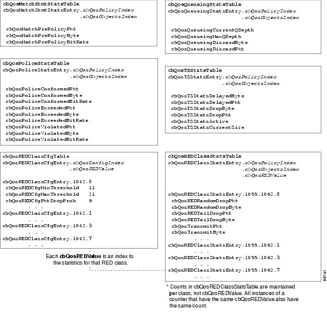
Sample QoS Statistics Tables
The samples in this section show the counters in CISCO-CLASS-BASED-QOS-MIB statistics tables:
•
•
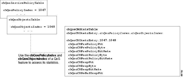
For ease-of-use, the following figures show some counters as a single object even though the counter is implemented as three objects. For example, cbQosCMPrePolicyByte is implemented as:
•
•
•
Figure 5-3 QoS Class Map Statistics and Indexes
Figure 5-4 QoS Statistics Tables
Sample QoS Applications
This section presents examples of code showing how to retrieve information from the CISCO-CLASS-BASED-QOS-MIB to use for QoS billing operations. You can use the examples to help you develop billing applications. The topics include:
•
•
Checking Customer Interfaces for Service Policies
This section describes a sample algorithm that checks the CISCO-CLASS-BASED-QOS-MIB for customer interfaces with service policies, and marks those interfaces for further application processing (such as billing for QoS services).
The algorithm uses two SNMP get-next requests for each customer interface. For example, if the router has 2000 customer interfaces, 4000 SNMP get-next requests are required to determine if those interfaces have transmit and receive service policies associated with them.
Note
Check the MIB to see which interfaces are associated with a customer. Create a pair of flags to show if a service policy has been associated with the transmit and receive directions of a customer interface. Mark noncustomer interfaces TRUE (so no more processing is required for them).
FOR each ifEntry DOIF (ifEntry represents a customer interface) THENservicePolicyAssociated[ifIndex].transmit = FALSE;servicePolicyAssociated[ifIndex].receive = FALSE;ELSEservicePolicyAssociated[ifIndex].transmit = TRUE;servicePolicyAssociated[ifIndex].receive = TRUE;END-IFEND-FORExamine the cbQosServicePolicyTable and mark each customer interface that has a service policy attached to it. Also note the direction of the interface.
x = 0;done = FALSE;WHILE (!done)status = snmp-getnext (ifIndex = cbQosIfIndex.x,direction = cbQosPolicyDirection.x);IF (status != `noError') THENdone = TRUEELSEx = extract cbQosPolicyIndex from response;IF (direction == `output') THENservicePolicyAssociated[ifIndex].transmit = TRUE;ELSEservicePolicyAssociated[ifIndex].receive = TRUE;END-IFEND-IFEND-WHILEManage cases in which a customer interface does not have a service policy attached to it.
FOR each ifEntry DOIF (!servicePolicyAssociated[ifIndex].transmit) THENPerform processing for customer interface without a transmit service policy.END-IFIF (!servicePolicyAssociated[ifIndex].receive) THENPerform processing for customer interface without a receive service policy.END-IFEND-FORRetrieving QoS Billing Information
This section describes a sample algorithm that uses the CISCO-CLASS-BASED-QOS-MIB for QoS billing operations. The algorithm periodically retrieves post-policy input and output statistics, combines them, and sends the result to a billing database.
The algorithm uses the following:
•
•
•
Note
Set up customer billing information.
FOR each ifEntry DOIF (ifEntry represents a customer interface) THENstatus = snmp-getnext (id = ifAlias.ifIndex);IF (status != `noError') THENPerform error processing.ELSEbilling[ifIndex].isCustomerInterface = TRUE;billing[ifIndex].customerID = id;billing[ifIndex].transmit = 0;billing[ifIndex].receive = 0;END-IFELSEbilling[ifIndex].isCustomerInterface = FALSE;END-IFEND-FORRetrieve billing information.
x = 0;done = FALSE;WHILE (!done)response = snmp-getnext (ifIndex = cbQosIfIndex.x,direction = cbQosPolicyDirection.x);IF (response.status != `noError') THENdone = TRUEELSEx = extract cbQosPolicyIndex from response;IF (direction == `output') THENbilling[ifIndex].transmit = GetPostPolicyBytes (x);ELSEbilling[ifIndex].receive = GetPostPolicyBytes (x);END-IFEND-IFEND-WHILEDetermine the number of post-policy bytes for billing purposes.
GetPostPolicyBytes (policy)x = policy;y = 0;total = 0;WHILE (x == policy)response = snmp-getnext (type = cbQosObjectsType.x.y);IF (response.status == `noError')x = extract cbQosPolicyIndex from response;y = extract cbQosObjectsIndex from response;IF (x == policy AND type == `classmap')status = snmp-get (bytes = cbQosCMPostPolicyByte64.x.y);IF (status == `noError')total += bytes;END-IFEND-IFEND-IFEND-WHILERETURN total;Monitoring Router Interfaces
This section provides information about how to monitor the status of router interfaces to see if there is a problem or a condition that might affect service on the interface. To determine if an interface is Down or experiencing problems, you can:
•
•
Check the Operational and Administrative Status of Interface
To check the status of an interface, view the following IF-MIB objects for the interface:
•
•
Monitor linkDown and linkUp Notifications
To determine if an interface has failed, you can monitor linkDown and linkUp notifications for the interface. See the "Enabling Interface linkUp and linkDown Notifications" section for instructions on how to enable the following notifications:
•
•
Enabling Interface linkUp and linkDown Notifications
To configure SNMP to send a notification when a router interface changes state to up (ready) or down (not ready), perform the following steps to enable linkUp and linkDown notifications:
Step 1
Router(config)# snmp-server interface <Interface Type> <Interface Number> notification
linkupdown
Step 2
Step 3
Step 4
Router(config)# snmp-server trap link ietfStep 5
Billing Customers for Traffic
This section describes how to use SNMP interface counters and QoS data information to determine the amount to bill customers for traffic. It also includes a scenario for demonstrating that a QoS service policy attached to an interface is policing traffic on that interface.
This section contains the following topics:
•
•
•
Input and Output Interface Counts
The router maintains information about the number of packets and bytes that are received on an input interface and transmitted on an output interface.
For detailed constraints about IF-MIB counter support, see the "IF-MIB (RFC 2863)" section.
Consider the following important information about IF-MIB counter support:
•
•
–
–
–
•
The following CISCO-CLASS-BASED-QOS-MIB objects provide interface counts:
•
•
Determining the Amount of Traffic to Bill to a Customer
Perform the following steps to determine how much traffic on an interface is billable to a particular customer:
Step 1
Step 2
Step 3
Step 4
Scenario for Demonstrating QoS Traffic Policing
This section describes a scenario that demonstrates the use of SNMP QoS statistics to determine how much traffic on an interface is billable to a particular customer. It also shows how packet counts are affected when a service policy is applied to traffic on the interface.
To create the scenario, perform the following steps (each step described in the section below):
1.
2.
3.
4.
•
•
Note
Service Policy Configuration
The following example uses policy map configuration.
policy-map police-outclass BGPclasspolice 8000 1000 2000 conform-action transmit exceed-action dropinterface GigabitEthernet0/1/0/0.10description VLAN voor klantencapsulation dot1Q 10ip address 10.0.0.17 255.255.255.248service-policy output police-outPacket Counts Before the Service Policy Is Applied
The following CLI and SNMP output shows the output traffic for interface before the service policy is applied:
CLI Command Output
RSP/0/RSP0/CPU0:ios-xr#show policy-map interface GigabitEthernet0/7/0/0.1GigabitEthernet0/7/0/0.1 input: policy-policeClass class-outClassification statistics (packets/bytes) (rate - kbps)Matched : 0/0 0Transmitted : Un-determinedTotal Dropped : Un-determinedPolicing statistics (packets/bytes) (rate - kbps)Policed(conform) : 0/0 0Policed(exceed) : 0/0 0Policed(violate) : 0/0 0Policed and dropped : 0/0Class class-defaultClassification statistics (packets/bytes) (rate - kbps)Matched : 0/0 0Transmitted : Un-determinedTotal Dropped : Un-determinedSNMP Output
ASR 9000# getone -v2c 10.86.0.63 public ifDescr.65ifDescr.65 = GigabitEthernet0/6/0/0.10Generating Traffic
The following set of ping commands generates traffic:
ASR 9000#pingProtocol [ip]:Target IP address: 10.0.0.18Repeat count [5]: 99Datagram size [100]: 1400Timeout in seconds [2]: 1Extended commands [n]:Sweep range of sizes [n]:Type escape sequence to abort.Sending 100, 1400-byte ICMP Echos to 10.0.0.18, timeout is 1 seconds:..!!..!..!..!..!.!.!..!.!..!.!..!.!.!..!.!..!.!..!.!.!..!.!..!.!..!.!.!..!.!..!.!..!.!.!..!.!..!.!..!.!Success rate is 42 percent (42/100), round-trip min/avg/max = 1/1/1 msPacket Counts After the Service Policy Is Applied
After you generate traffic using the ping command, look at the number of packets that exceeded and conformed to the committed access rate (CAR) set by the police command:
•
•
The following CLI and SNMP output show the counts on the interface after the service policy is applied. (In the output, conformed and exceeded packet counts are shown in boldface.)
CLI Command Output
ASR 9000# show policy-map interface g6/0/0.10GigabitEthernet6/0/0.10Service-policy output: police-outClass-map: BGPclass (match-all)198 packets, 281556 bytes30 second offered rate 31000 bps, drop rate 11000 bpsMatch: access-group 101Police:8000 bps, 1000 limit, 2000 extended limitconformed 42 packets, 59892 bytes; action: transmitexceeded 57 packets, 81282 bytes; action: dropClass-map: class-default (match-any)15 packets, 1086 bytes30 second offered rate 0 bps, drop rate 0 bpsMatch: anyOutput queue: 0/8192; 48/59940 packets/bytes output, 0 dropsSNMP Output
ASR 9000# getmany -v2c 10.86.0.63 public ciscoCBQosMIB. . .cbQosCMDropPkt.1143.1145 = 57. . .cbQosPoliceConformedPkt.1143.1151 = 42. . .Using IF-MIB Counters
This section describes the IF-MIB counters and how you can use them on various interfaces and subinterfaces. The subinterface counters are specific to the protocols. This section addresses the IF-MIB counters for ATM interfaces.
The IF-MIB counters are defined with respect to lower and upper layers:
•
•
•
•
•
The logical flow for counters works as follows:
1.
a.
b.
c.
d.
2.
a.
b.
c.
This following output is an example of IF-MIB entries:
IfXEntry ::=
SEQUENCE {ifName DisplayString,ifInMulticastPkts Counter32,ifInBroadcastPkts Counter32,ifOutMulticastPkts Counter32,ifOutBroadcastPkts Counter32,ifHCInOctets Counter64,ifHCInUcastPkts Counter64,ifHCInMulticastPkts Counter64,ifHCInBroadcastPkts Counter64,ifHCOutOctets Counter64,ifHCOutUcastPkts Counter64,ifHCOutMulticastPkts Counter64,ifHCOutBroadcastPkts Counter64,ifLinkUpDownTrapEnable INTEGER,ifHighSpeed Gauge32,ifPromiscuousMode TruthValue,ifAlias DisplayString,ifCounterDiscontinuityTime TimeStampSample Counters
The high capacity counters are 64-bit versions of the basic ifTable counters. They have the same basic semantics as their 32-bit counterparts; their syntax is extended to 64 bits.
Table 5-2 lists capacity counters object identifiers (OIDs).