Feedback Feedback
|
Table Of Contents
Installing a Cisco 2691 Redundant Power Supply Interface Module in the Cisco 2691 Router
Working Safely with Electricity
Preventing Electrostatic Discharge Damage
Overview of the Cisco 2691 RPS Interface Module
Power Requirements for the Cisco 2691 RPS Interface Module
How to Remove the Power Supply from the Cisco 2691 Router
Removing the Cover from the Cisco 2691 Router
Removing the Power Supply from the Cisco 2691 Router
How to Install the Cisco 2691 RPS Interface Module in the Cisco 2691 Router
Attaching the Adapter Panel and Interface Module to the Cisco 2691 Chassis Rear Panel
Connecting the Redundant Power Supply Interface Module Cables to the Cisco 2691 Router
Replacing the Flash Memory Card in the Cisco 2691 Chassis
Replacing the Cover on the Cisco 2691 Router
Attaching the Voltage Label to the Cisco 2691 Chassis
How to Reconnect the Cisco 2691 Router
Connecting the Cisco 2691 Router to Building Ground
Reinstalling the Cables and Connecting to the Cisco 600W RPS System Module
About Troubleshooting the Cisco 2691 RPS Interface Module
Obtaining Technical Assistance
Installing a Cisco 2691 Redundant Power Supply Interface Module in the Cisco 2691 Router
Product Number: ACS-2691RPS=
Document Number: 78-14829-01
November, 2002Purpose
This document provides instructions for removing the power supply from the Cisco 2691 router, installing the Cisco 2691 redundant power supply (RPS) interface module, and connecting to the Cisco 600W redundant power supply (RPS) system module.
Audience
This document is intended for the power supply installer, who should be familiar with electronic circuitry and wiring practices and have experience as an electronic or electromechanical technician.
Warning
Only trained and qualified personnel should be allowed to install, replace, or service this equipment. To see translations of the warnings that appear in this publication, refer to the Regulatory Compliance and Safety Information document that accompanied this device.
Scope
This document covers the following areas:
•
•
•
Use this document with the Cisco 2600 Series Hardware Installation Guide and the Regulatory Compliance and Safety Information document for your router. If you have questions or need help, refer to the "Obtaining Technical Assistance" section.
Contents
This document contains the following sections:
•
•
•
•
•
•
•
Safety Information
Follow these guidelines to ensure general safety:
•
•
•
•
•
•
Warning
Warning
Warning
Warning
Warning
Warning
Also read the following information before proceeding:
•
•
Working Safely with Electricity
Follow these guidelines when working on equipment powered by electricity:
•
•
•
–
–
–
•
•
•
•
–
–
–
–
Preventing Electrostatic Discharge Damage
Electrostatic discharge (ESD) can damage equipment and impair electrical circuitry. It occurs when electronic printed circuit cards are improperly handled and can result in complete or intermittent failures. Always follow ESD prevention procedures when removing and replacing cards. Ensure that the router chassis is electrically connected to earth ground. Wear an ESD-preventive wrist strap, ensuring that it makes good skin contact. Connect the clip to an unpainted surface of the chassis frame to safely channel unwanted ESD voltages to ground. To properly guard against ESD damage and shocks, the wrist strap and cord must operate effectively. If no wrist strap is available, ground yourself by touching the metal part of the chassis.
Caution
Warning Definition
Overview of the Cisco 2691 RPS Interface Module
The Cisco 2691 RPS interface module replaces the power supply installed in the router. The interface module connects to the Cisco 600W RPS system module using a one-to-one or two-to-one cable.
The interface module is used to convert and distribute incoming DC power from the Cisco 600W RPS system module to the DC voltage used by the router. The interface module has four regulated DC outputs:
•
•
•
•
Two cables connect the interface module to the Cisco 2691 router motherboard:
•
•
For cable pinout information see the "About Troubleshooting the Cisco 2691 RPS Interface Module" section.
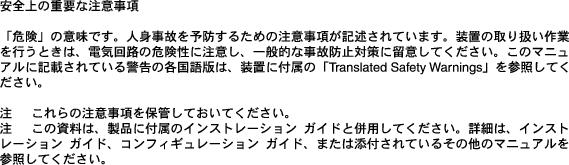
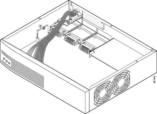
Figure 1 shows the redundant power supply interface module for the Cisco 2691 router.
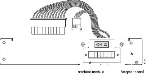
Figure 2 shows the location of the interface module in the Cisco 2691 router.
Figure 1 Cisco 2691 Redundant Power Supply Interface Module
Figure 2 Redundant Power Supply Interface Module Location in the Cisco 2691 Router
Power Requirements for the Cisco 2691 RPS Interface Module
Table 2 lists the VDC output from the Cisco 2691 router redundant power supply interface module to the motherboard and the input voltage from the Cisco 600 external power supply to the Cisco 2691 redundant power supply interface module
Table 1 Input from Redundant Power Supply Cisco 600W RPS
Output voltage from the interface module
+3, +5, +12, -12 VDC
Input voltage from Cisco RPS600
+5, +12, and -12 VAC
How to Remove the Power Supply from the Cisco 2691 Router
The power supply for the Cisco 2691 router is located inside the chassis. To remove the power supply, complete these procedures:
•
•
•
Safety
Before opening the Cisco 2691 router and removing the power supply, please read these warnings:
Warning
Warning
Warning
Warning
Warning
Removing the Cover from the Cisco 2691 Router
Tools
•
•
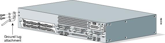
To remove the cover, follow these steps:
Step 1
Step 2
Step 3
Step 4
Figure 3 Locating the Chassis Ground Lugs
Step 5
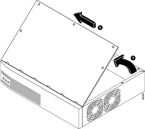
Step 6
Step 7
Step 8
Figure 4 Removing the Cisco 2691 Cover
Step 9
Removing the Power Supply from the Cisco 2691 Router
Tools
•
•
After you remove the cover from the chassis, follow these steps to remove the power supply:
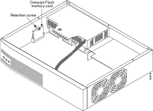
Step 1
Figure 5 Cisco 2691 Compact Flash Location
Step 2
Step 3
Step 4
Note
Figure 6 Disconnecting the Cisco 2691 Power Connector
Step 5
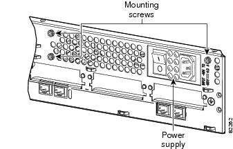
Figure 7 Cisco 2691 Power Supply Mounting Screws
Step 6
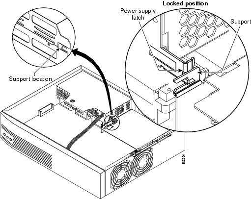
Figure 8 Cisco 2691 Power Supply Mounting Support (Right)
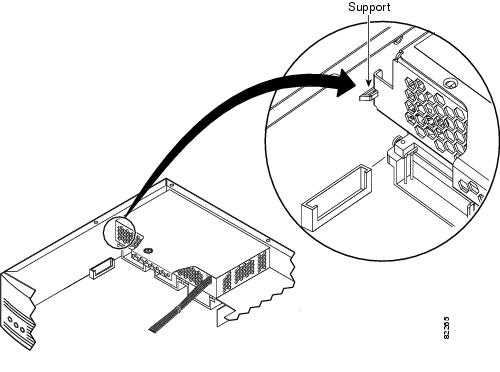
Figure 9 Cisco 2691 Power Supply Mounting Support (Left)
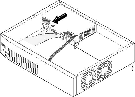
Step 7
Figure 10 Removing the Cisco 2691 Power Supply
How to Install the Cisco 2691 RPS Interface Module in the Cisco 2691 Router
The Cisco 2691 RPS interface module comes attached to an adapter panel. The adapter panel with the interface module is installed in the Cisco 2691 router as a unit.
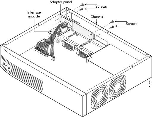
Attaching the Adapter Panel and Interface Module to the Cisco 2691 Chassis Rear Panel
The adapter panel with the interface module attached, is installed behind the rear panel of the chassis.
Tools
•
•
•
•
Step 1
Step 2
Figure 11 Aligning the Adapter Panel with the Chassis Rear Panel
Step 3
Note
Step 4
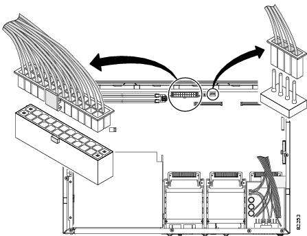
Connecting the Redundant Power Supply Interface Module Cables to the Cisco 2691 Router
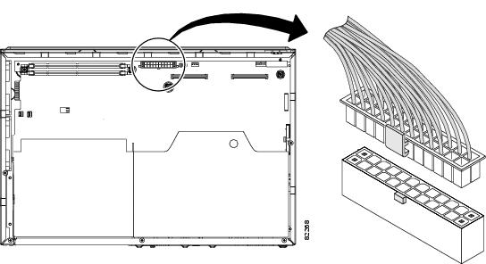
The two cables coming from the back of the interface module are attached to connectors on the back of the motherboard in the Cisco 2691 router chassis.
Step 1
Figure 12 Connecting the Power Cables to the Motherboard
Replacing the Flash Memory Card in the Cisco 2691 Chassis
Tools
•
•
Before you replace the cover on the chassis, follow these steps to replace the compact Flash memory card:
Step 1
Step 2
Step 3
Figure 13 Replacing the Compact Flash Memory Card in the Chassis
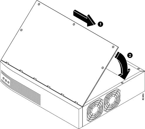
Replacing the Cover on the Cisco 2691 Router
After you finish installing the Cisco redundant power supply interface module, follow these steps to replace the cover:
Step 1
Step 2
Step 3
Step 4
Step 5
Figure 14 Replacing the Cisco 2691 Router Cover
Step 6
Attaching the Voltage Label to the Cisco 2691 Chassis
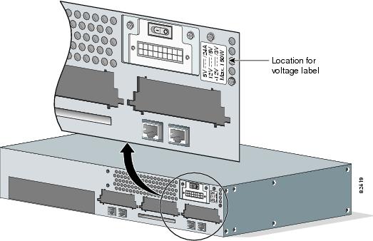
The Cisco 2691 RPS interface module kit comes with a self-adhesive label that must be placed on the rear of the chassis after the interface module is installed. This label shows the available voltages and maximum wattage when the interface module is installed in the chassis.
Step 1
Step 2
Figure 15 Placing the Voltage Label on the Chassis
How to Reconnect the Cisco 2691 Router
After the router cover has been installed, return the Cisco 2691 router to the telco rack or installation location.
Warning
Caution
Connecting the Cisco 2691 Router to Building Ground
To connect the building ground wire to the Cisco 2691 router, follow these steps:
Note
Warning
Step 1
Step 2
Figure 16 NEBS-Compliant Ground Connection on the Cisco 2691 Router
Step 3
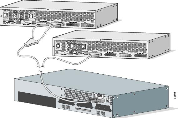
Reinstalling the Cables and Connecting to the Cisco 600W RPS System Module
Step 1
Step 2
Step 3
Figure 17 Connecting the Cisco 2691 Router to the Cisco 600W RPS Module
Step 4
Note
For information about the Cisco 600W redundant power supply system, refer to the Cisco Redundant Power Supply System Hardware Installation Guide at the following URL:|
http://www.cisco.com/univercd/cc/td/doc/product/access/rpsbk/rpshim/index.htm
Powering On the Router
Warning
Caution
Warning
To power on the router, perform the following steps:
Step 1
Step 2
If you encounter problems when you power on the router, see the "About Troubleshooting the Cisco 2691 RPS Interface Module" section.
About Troubleshooting the Cisco 2691 RPS Interface Module
Check the following items to help isolate problems with the Cisco 2691 RPS interface module installation:
•
–
–
–
•
–
–
–
–
•
Table 2 lists the VDC output from the Cisco 2691 RPS interface module to the motherboard.
Table 1 shows the output voltage from the Cisco 600W RPS module to the Cisco 2691 RPS interface module.
Table 3 Cisco 600W RPS System Module Output Voltage
Cisco 600W RPS system module output to the Cisco 2691 RPS interface module
+5, +12, and -12 VDC
Table 4 shows the cable pinouts for the cables from the interface module to the Cisco 2691 router motherboard.
Table 5 AC Interface Module Cable Pin Assignments (RPS Signals)
1
GND
3
FAIL_0
2
RPS_FAIL
4
FAIL_1
Related Documentation
Check the following websites for more information about the Cisco 2691 router:
•
http://www.cisco.com/univercd/cc/td/doc/product/access/acs_mod/cis2600/2600_qsg.htm
•
http://www.cisco.com/univercd/cc/td/doc/product/access/acs_mod/cis2600/hw_inst/index.htm
•
•
http://www.cisco.com/univercd/cc/td/doc/product/access/acs_mod/cis2600/sw_conf/index.htm
•
http://www.cisco.com/univercd/cc/td/doc/product/access/acs_mod/cis2600/2600indx.htm
•
http://www.cisco.com/univercd/cc/td/doc/product/access/acs_mod/cis2600/rn2600/index.htm
http://www.cisco.com/univercd/cc/td/doc/product/access/acs_mod/cis2600/rcsi/index.htm
•
http://www.cisco.com/univercd/cc/td/doc/product/access/acs_mod/cis2600/secure/index.htm
•
http://www.cisco.com/pcgi-bin/Support/PSP/psp_view.pl?p=Hardware:2600
Obtaining Documentation
These sections explain how to obtain documentation from Cisco Systems.
World Wide Web
You can access the most current Cisco documentation on the World Wide Web at this URL:
Translated documentation is available at this URL:
http://www.cisco.com/public/countries_languages.shtml
Documentation CD-ROM
Cisco documentation and additional literature are available in a Cisco Documentation CD-ROM package, which is shipped with your product. The Documentation CD-ROM is updated monthly and may be more current than printed documentation. The CD-ROM package is available as a single unit or through an annual subscription.
Ordering Documentation
You can order Cisco documentation in these ways:
•
http://www.cisco.com/cgi-bin/order/order_root.pl
•
http://www.cisco.com/go/subscription
•
Documentation Feedback
You can submit comments electronically on Cisco.com. In the Cisco Documentation home page, click the Fax or Email option in the "Leave Feedback" section at the bottom of the page.
You can e-mail your comments to bug-doc@cisco.com.
You can submit your comments by mail by using the response card behind the front cover of your document or by writing to the following address:
Cisco Systems
Attn: Document Resource Connection
170 West Tasman Drive
San Jose, CA 95134-9883We appreciate your comments.
Obtaining Technical Assistance
Cisco provides Cisco.com as a starting point for all technical assistance. Customers and partners can obtain online documentation, troubleshooting tips, and sample configurations from online tools by using the Cisco Technical Assistance Center (TAC) Web Site. Cisco.com registered users have complete access to the technical support resources on the Cisco TAC Web Site.
Cisco.com
Cisco.com is the foundation of a suite of interactive, networked services that provides immediate, open access to Cisco information, networking solutions, services, programs, and resources at any time, from anywhere in the world.
Cisco.com is a highly integrated Internet application and a powerful, easy-to-use tool that provides a broad range of features and services to help you with these tasks:
•
•
•
•
•
If you want to obtain customized information and service, you can self-register on Cisco.com. To access Cisco.com, go to this URL:
Technical Assistance Center
The Cisco Technical Assistance Center (TAC) is available to all customers who need technical assistance with a Cisco product, technology, or solution. Two levels of support are available: the Cisco TAC Web Site and the Cisco TAC Escalation Center.
Cisco TAC inquiries are categorized according to the urgency of the issue:
•
•
•
•
The Cisco TAC resource that you choose is based on the priority of the problem and the conditions of service contracts, when applicable.
Cisco TAC Web Site
You can use the Cisco TAC Web Site to resolve P3 and P4 issues yourself, saving both cost and time. The site provides around-the-clock access to online tools, knowledge bases, and software. To access the Cisco TAC Web Site, go to this URL:
All customers, partners, and resellers who have a valid Cisco service contract have complete access to the technical support resources on the Cisco TAC Web Site. The Cisco TAC Web Site requires a Cisco.com login ID and password. If you have a valid service contract but do not have a login ID or password, go to this URL to register:
http://www.cisco.com/register/
If you are a Cisco.com registered user, and you cannot resolve your technical issues by using the Cisco TAC Web Site, you can open a case online by using the TAC Case Open tool at this URL:
http://www.cisco.com/tac/caseopen
If you have Internet access, we recommend that you open P3 and P4 cases through the Cisco TAC Web Site.
Cisco TAC Escalation Center
The Cisco TAC Escalation Center addresses priority level 1 or priority level 2 issues. These classifications are assigned when severe network degradation significantly impacts business operations. When you contact the TAC Escalation Center with a P1 or P2 problem, a Cisco TAC engineer automatically opens a case.
To obtain a directory of toll-free Cisco TAC telephone numbers for your country, go to this URL:
http://www.cisco.com/warp/public/687/Directory/DirTAC.shtml
Before calling, please check with your network operations center to determine the level of Cisco support services to which your company is entitled: for example, SMARTnet, SMARTnet Onsite, or Network Supported Accounts (NSA). When you call the center, please have available your service agreement number and your product serial number.
This document is to be used in conjunction with the documents listed in the "Related Documentation" section.
CCIP, the Cisco Arrow logo, the Cisco Powered Network mark, the Cisco Systems Verified logo, Cisco Unity, Follow Me Browsing, FormShare, iQ Breakthrough, iQ Expertise, iQ FastTrack, the iQ Logo, iQ Net Readiness Scorecard, Networking Academy, ScriptShare, SMARTnet, TransPath, and Voice LAN are trademarks of Cisco Systems, Inc.; Changing the Way We Work, Live, Play, and Learn, Discover All That's Possible, The Fastest Way to Increase Your Internet Quotient, and iQuick Study are service marks of Cisco Systems, Inc.; and Aironet, ASIST, BPX, Catalyst, CCDA, CCDP, CCIE, CCNA, CCNP, Cisco, the Cisco Certified Internetwork Expert logo, Cisco IOS, the Cisco IOS logo, Cisco Press, Cisco Systems, Cisco Systems Capital, the Cisco Systems logo, Empowering the Internet Generation, Enterprise/Solver, EtherChannel, EtherSwitch, Fast Step, GigaStack, Internet Quotient, IOS, IP/TV, LightStream, MGX, MICA, the Networkers logo, Network Registrar, Packet, PIX, Post-Routing, Pre-Routing, RateMUX, Registrar, SlideCast, StrataView Plus, Stratm, SwitchProbe, TeleRouter, and VCO are registered trademarks of Cisco Systems, Inc. and/or its affiliates in the U.S. and certain other countries.
All other trademarks mentioned in this document or Web site are the property of their respective owners. The use of the word partner does not imply a partnership relationship between Cisco and any other company. (0208R)
Copyright © 2002, Cisco Systems, Inc.
All rights reserved.