-
Cisco 1800 Series Hardware Installation (Modular)
-
Introduction to Cisco 1800 Series Routers (Modular) Hardware Documentation
-
Overview of Cisco 1800 Series Routers (Modular)
-
Preinstallation Requirements and Planning for Cisco 1800 Series Routers (Modular)
-
Chassis Installation Procedures for Cisco 1800 Series Routers (Modular)
-
Cable Information and Specifications for Cisco 1800 Series Routers (Modular)
-
Cable Connection Procedures for Cisco 1800 Series Routers (Modular)
-
Power-Up Procedures for Cisco 1800 Series Routers (Modular)
-
Troubleshooting Cisco 1800 Series Routers (Modular)
-
Installing Interface Cards in Cisco 1800 Series Routers (Modular)
-
Installing and Replacing CompactFlash Memory Cards on Cisco 1800 Series Routers (Modular)
-
Installing and Upgrading Internal Modules in Cisco 1800 Series Routers (Modular)
-
 Feedback
Table Of Contents
Overview of Cisco 1800 Series Routers (Modular)
Product Serial Number Location
Cisco Product Identification Tool
Removable and Interchangeable Modules
Overview of Cisco 1800 Series Routers (Modular)
Cisco 1800 series integrated services routers (modular) are modular routers with LAN and WAN connections that can be configured by means of interchangeable interface cards and advanced integration modules (AIMs). The modular design of the routers provides flexibility, allowing you to configure or reconfigure your router according to your needs.
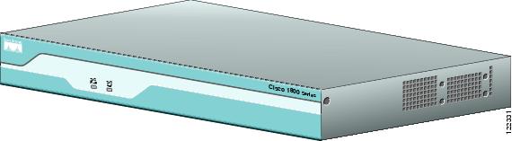
There is one router in the Cisco 1800 series (modular). The Cisco 1841 router is a data-only device for desktop use.
Figure 1 shows the Cisco 1841 router.
Figure 1 The Cisco 1841 Router
This chapter describes the features and specifications of the router and includes the following sections:
Hardware Features
This section describes the basic features of Cisco 1800 series routers. It contains the following:
•
Product Serial Number Location
•
Product Serial Number Location
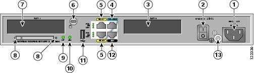
The serial number label for Cisco 1841 router is located on the rear of the chassis, underneath interface card slot 0. (See Figure 2.)
Figure 2 Serial Number Location
Note
Cisco Product Identification Tool
The Cisco Product Identification (CPI) tool provides detailed illustrations and descriptions showing where to locate serial number labels on Cisco products. It includes the following features:
•
•
•
The tool streamlines the process of locating serial number labels and identifying products. Serial number information expedites the entitlement process and is important for access to support services.
The Cisco Product Identification tool can be accessed at the following URL:
http://tools.cisco.com/Support/CPI/index.do
Built-In Interfaces
This section summarizes the interfaces available on the Cisco 1800 series routers:
•
•
•
Removable and Interchangeable Modules
Various optional modules can be installed in the router to provide specific capabilities. These modules can be installed either by inserting them into slots on the chassis, or by opening the chassis and plugging them into connectors inside.
•
There are three types of interface cards for the 1800 series modular routers:
–
–
–
•
–
–
Table 1 summarizes the optional modules:
Table 1 Summary of Cisco 1800 Series Removable and Interchangeable Modules
Cisco 1841
1
2 single-wide cards
1
1
Memory
Cisco 1800 series routers contain the following types of memory:
•
•
•
Table 2 lists the memory specifications for Cisco 1800 series routers.
Table 2 Router Memory Specifications
SDRAM
128 MB, expandable to 384 MB; default is 128 MB
Flash memory
32, 64, or 128 MB; default is 32MB
Boot/NVRAM
2/4 MB flash memory
Note
LED Indicators
Table 3 summarizes the LED indicators that are located in the router bezel or chassis, but not in the interface cards.
For descriptions of the LEDs in the interface cards, refer to the Cisco Interface Card Installation Guide.
Chassis Ventilation
An internal three-speed fan provides chassis cooling. An onboard temperature sensor controls the fan speed. The fan is always on when power is applied to the router. Under most conditions, the fan operates at the slowest speed to conserve power and reduce fan noise. It operates at the higher speeds when necessary under conditions of higher ambient temperature.
Real-Time Clock
An internal real-time clock with battery backup provides the system software with time of day on system power up. This allows the system to verify the validity of a certification authority (CA) certificate. The backup battery is a socketed lithium battery. This battery lasts the life of the router under the operating environmental conditions specified for the router, and is not field replaceable.
Note
Warning
Chassis Security
The chassis of the Cisco 1841 router is constructed with a KensingtonTM security slot on the back panel. It can be secured to a desktop or other surface by using KensingtonTM lockdown equipment.
Chassis Views
This section contains views of the front and rear panels of Cisco 1800 series routers, showing the locations of the power and signal interfaces, the interface card slots, and the status indicators.
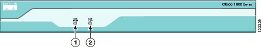
Figure 3 shows the front panel of a Cisco 1841 router. Figure 4 shows the back panel.
Figure 3 Front Panel of the Cisco 1841 Router
Figure 4 Back Panel of the Cisco 1841 Router
Interface Numbering
Each individual interface (port) on a Cisco 1841 router is identified by a number. A Cisco 1841 router contains the following wide-area network (WAN) and local-area network (LAN) interface types:
•
•
The numbering format for the slots is interface-type 0/slot-number/interface-number. Table 4 summarizes the interface numbering.
Table 4 Interface Numbering
Onboard Ports
Fast Ethernet
0/0 and 0/1
interface fastethernet 0/0
Slot 0
HWIC/WIC/VWIC2
0/0/0 to 0/0/3
interface serial 0/0/0
line async 0/0/0
Slot 1
HWIC/WIC/VWIC2
0/1/0 to 0/1/3
interface serial 0/1/0
line async 0/1/0
1 The interfaces listed are examples only; other possible interface types are not listed.
2 VWICs are data-only in a Cisco 1841 router.
Note
Specifications
Table 5 lists the specifications for Cisco 1800 series routers.
Table 5 1841 Router Specifications
Dimensions without rubber feet
(H x W x D)1.73 x 13.5 x 10.8 in. (4.4 x 34.3 x 27.4 cm)
With rubber feet, height is 1.87 in. (4.75 cm)Weight (no modules installed)
6.1 lb. (2.77 kg)
Input voltage, AC power supply
Frequency100 to 240 VAC, autoranging
47 to 63 HzPower consumption
20 W maximum for an unloaded unit.
With two WICs and an AIM installed, power consumption will be
less than 50 W.Console and auxiliary ports
RJ-45 connectors
Operating humidity
5 to 95%, noncondensing
Operating temperature
32 to 104°F (0 to 40°C)
Nonoperating temperature shock
-13 to 158°F (-25 to 70°C) at 9° F (5° C)/minute minimum
Noise level
Normal operating temperature (< 78° F or 26° C): 34 dBa
From (78° F or 26° C) through (104° F or 40° C): 37 dBa
>104° F or 40° C: 42 dBaRegulatory compliance
For detailed regulatory compliance information, refer to the
Regulatory Compliance and Safety Information for Cisco 1840
Routers document that accompanies the router.Electromagnetic compatibility
FCC Part 15 Class A.
Safety compliance
UL 60950; CSA 60950; IEC 60950; EN 60950; AS/NZS 3260; NOM-019-SCFI-1998.
Regulatory Compliance
For compliance information, refer to the Regulatory Compliance and Safety Information for Cisco 1840 Routers document that accompanies the router.
Copyright © 2004 Cisco Systems, Inc. All rights reserved.