Table Of Contents
Chassis Installation Procedures
Setting Up the Chassis
Setting a Cisco 1800 Series Fixed-Configuration Router on a Desktop
Chassis Grounding
Mounting a Cisco 1800 Series Fixed-Configuration Router on a Wall
Installing the Chassis Ground Connection
Chassis Installation Procedures
This chapter describes how to install your Cisco 1800 series fixed-configuration router on a desktop or on a wall. It includes the following sections:
•
Setting Up the Chassis
•
Installing the Chassis Ground Connection
Note
To see translations of the warnings that appear in this publication, see the Regulatory Compliance and Safety Information for Cisco 1800 Integrated Services Routers (Fixed) document that accompanied this device.
Warning
Only trained and qualified personnel should be allowed to install, replace, or service this equipment. Statement 1030
Warning
This unit is intended for installation in restricted access areas. A restricted access area can be accessed only through the use of a special tool, lock and key, or other means of security. Statement 1017
Setting Up the Chassis
Warning
Before working on a system that has an on/off switch, turn OFF the power and unplug the power cord. Statement 1
You can set a Cisco 1800 series fixed-configuration router on a desktop or mount it on a wall. See the applicable instructions in the following sections.
•
Setting a Cisco 1800 Series Fixed-Configuration Router on a Desktop
•
Chassis Grounding
•
Mounting a Cisco 1800 Series Fixed-Configuration Router on a Wall
Caution 
To prevent damage to the chassis, never attempt to lift or tilt the chassis by holding the plastic panel on the front. Always hold the chassis by the metal body.
Setting a Cisco 1800 Series Fixed-Configuration Router on a Desktop
You can place Cisco 1800 series fixed-configuration routers on a desktop or shelf. Do not place anything on top of the router that weighs more than 10 pounds (4.5 kilograms), and do not stack routers on a desktop. Excessive weight on top of the router could damage the chassis.
Caution 
Your chassis installation must allow unrestricted airflow for chassis cooling. When placing the router on a desktop, keep at least 1 inch (2.5 cm) of clear space beside the cooling inlet and exhaust vents.
After the router is installed, you must connect the chassis to a reliable earth ground. For the chassis ground connection procedures, see the "Installing the Chassis Ground Connection" section.
Chassis Grounding
After you install the router, you must connect the chassis to a reliable earth ground. For the chassis ground connection procedures, see the "Installing the Chassis Ground Connection" section.
Mounting a Cisco 1800 Series Fixed-Configuration Router on a Wall
The Cisco 1800 series fixed-configuration routers have slots on the bottom of the chassis for mounting the unit on a wall or other vertical surface.
Warning
This unit is intended to be mounted on a wall. Please read the wall mounting instructions carefully before beginning installation. Failure to use the correct hardware or to follow the correct procedures could result in a hazardous situation to people and damage to the system. Statement 248
Tip
When choosing a location for wall-mounting the router, consider cable limitations and wall structure.
Tip
If your router has the optional wireless LAN feature, before you mount the router on a wall, connect the antennas to the back panel. It is difficult to attach the antennas after the router has been mounted to a wall.
To attach the router to a wall, use the following hardware:
•
For attaching to a wall stud, use two number-10 wood screws (round- or pan-head) with number-10 washers, or two number-10 washer-head screws. The screws must be long enough to penetrate at least 3/4 inch (20 millimeters) into the supporting wood or metal wall stud.
•
For hollow-wall mounting, use two number-10 wall anchors with washers.
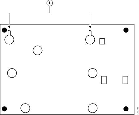
Figure 3-1 shows the underside of a Cisco 1800 series fixed-configuration router and the locations of the wall-mount holes.
Figure 3-1 Mount Holes on Underside of Cisco 1800 Series Fixed-Configuration Router Chassis
1
|
Holes for wall-mounting
|
After you install the router, you must connect the chassis to a reliable earth ground. For the chassis ground connection procedures, see the "Installing the Chassis Ground Connection" section.
Installing the Chassis Ground Connection
Warning
This equipment must be grounded. Never defeat the ground conductor or operate the equipment in the absence of a suitably installed ground conductor. Contact the appropriate electrical inspection authority or an electrician if you are uncertain that suitable grounding is available. Statement 1024
You must connect the chassis to a reliable earth ground; the ground wire must be installed in accordance with local electrical safety standards.
•
For NEC-compliant grounding, use size 14 AWG (2 mm2) or larger copper wire and an appropriate user-supplied ring terminal with an inner diameter of 1/4 inch (5 to 7 millimeters).
•
For EN/IEC 60950-compliant grounding, use size 18 AWG (1 mm2) or larger copper wire and an appropriate user-supplied ring terminal.
Follow these steps to install the ground connection:
Step 1
Strip one end of the ground wire to the length required for the ground lug or terminal.
Step 2
Crimp the ground wire to the ground lug or ring terminal, using a wire crimper of the appropriate size.
Step 3
Attach the ground lug or ring terminal to the chassis. For a ground lug, use the provided two screws with captive locking washers. For a ring terminal, use one of the screws provided. Tighten the screws to a torque of 8 to 10 in-lb (0.9 to 1.1 N-m).
Note
To see an illustration of this procedure, go to the following URL:
http://www.cisco.com/en/US/docs/routers/access/1800/1841/hardware/quick/guide/1800qsg.html
Step 4
Connect the other end of the ground wire to a known reliable earth ground point at your site.
After you install and properly ground the router, you can connect the power wiring, the WAN and LAN cables, and the cables for administrative access as required for your installation. For information about connecting the cables, see Chapter 4, "Power, Cable, and Antenna Connection Procedures."