Feedback
Table Of Contents
Product Serial Number Location
Cisco Product Identification Tool
Integrated 802.11a/b/g Radio Module (Wireless Models Only)
Supported Cisco Radio Antennas (Wireless Models Only)
Overview
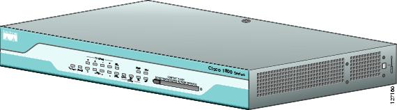
The Cisco 1800 series fixed-configuration routers are part of the new line of integrated services routers that are optimized for secure, fast, high-quality delivery of multiple, concurrent services for small-to-medium-sized businesses and small enterprise branch offices. The Cisco 1811 and Cisco 1812 routers offer an 8-port 10/100Base-T switch, dual 10/100Base-T WAN ports, two USB 2.0 ports, and either an ISDN S/T or an analog modem port. The Cisco 1801, Cisco 1802, and Cisco 1803 routers offer an 8-port 10/100Base-T switch; a single 10/100Base-T WAN port; an ISDN S/T port; and either an ADSL over POTS, ADSL over ISDN, or G.SHDSL WAN port. All models also offer embedded hardware-based encryption that provides superior performance for advanced applications, optional 802.11a/b/g wireless LAN functionality, an integrated real-time clock for validating digital certificates and stamping syslog entries, and optional Power over Ethernet (PoE).
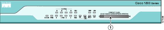
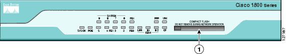
Figure 1-1 shows a front view of a Cisco 1800 series fixed-configuration router.
Figure 1-1 Front View of a Cisco 1800 Series Fixed-Configuration Router
This chapter describes the features and specifications of the routers and includes the following sections:
Hardware Features
This section describes the basic features of the Cisco 1800 series fixed-configuration routers, including product identification, built-in interfaces, memory, LED indicators, chassis ventilation, and the internal clock.
Product Serial Number Location
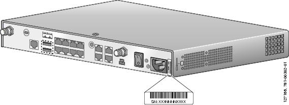
On the Cisco 1800 series fixed-configuration routers, the serial number label is located on the back of the chassis, along the bottom edge near the lower right corner. (See Figure 1-2.)
Figure 1-2 Serial Number Location
Note
The serial number for the Cisco 1800 series fixed-configuration routers is 11 characters long.
Cisco Product Identification Tool
The Cisco Product Identification (CPI) tool provides detailed descriptions and illustrations showing where to locate serial number labels on Cisco products. The CPI tool includes the following features:
•
•
•
The tool streamlines the process of locating serial number labels and identifying products. Serial number information expedites the entitlement process and is important for access to support services.
The Cisco Product Identification tool can be accessed at the following URL:
http://tools.cisco.com/Support/CPI/index.do
Feature Summary
Table 1-1 summarizes the built-in ports and other hardware features of the Cisco 1800 series fixed-configuration routers.
Memory
Cisco 1800 series fixed-configuration routers contain the following types of memory:
•
•
•
Power
Table 1-2 summarizes the AC power options for the Cisco 1800 series fixed-configuration routers.
LED Indicators
Table 1-3 summarizes the LED indicators that are located in the router front panel.
Table 1-3 Summary of LED Indicators on the Cisco 1800 Series Fixed-Configuration Routers
SYS OK
Green
The router has successfully booted up, and the software is functional. This LED blinks while booting or while in the ROM monitor mode.
WLAN
Green
This LED shows wireless access point link status. It is active only on wireless models.
On indicates that at least one client is associated.
Blinking green indicates that no client is associated.
POE1
Green/
AmberGreen indicates that the inline power supply is present.
Amber indicates a fault with the inline power supply.
Off indicates that the inline power supply is not installed.
FE <port number>
Green
These LEDs indicate Fast Ethernet port link and status for both FE WAN ports (ports 0 and 1 on the Cisco 1811 and Cisco 1812 routers; port 0 on the Cisco 1801, Cisco 1802, and Cisco 1803 routers) and the FE switch ports (ports 2 through 9 on the Cisco 1811 and Cisco 1812 routers; ports 1 through 8 on the Cisco 1801, Cisco 1802, and Cisco 1803routers).
Green indicates a successful FE link.
Off indicates no link.
CD2
Green
This LED indicates whether a connection is established (carrier detect). On the Cisco 1801, Cisco 1802, and Cisco 1803 routers, this LED indicates whether a DSL connection is established. On the Cisco 1811 router, this LED indicates whether a modem connection is established.
On indicates a connection is established.
Off indicates no connection established.
LPBK3
Green
On indicates the DSL interface is in loopback mode.
Off indicates DSL interface normal operation.
PPP
Green
On if at least one PPP connection is established.
VPN
Green
On if at least one VPN tunnel is established.
LINK4
Green
On indicates that an ISDN S/T connection has been established.
Off indicates that no ISDN S/T connection has been established.
B14
Green
Blinking green indicates activity on the first B channel.
Off indicates no activity on the first B channel.
B24
Green
Blinking green indicates activity on the second B channel.
Off indicates no activity on the second B channel.
SPD5
Green
On indicates a connection at high speed (V.90/V.92).
Off indicates a connection at low speed (V.32/V.32b/V.34).
BUSY5
Green
Blinking green indicates activity over the modem line.
Off indicates no activity.
CF
Green
On when CompactFlash memory is busy. Do not remove CompactFlash memory when this light is on.
1 Inline power is a field-upgradable option only. It is not installed by default.
2 This LED does not exist on the Cisco 1812.
3 This LED exists on the Cisco 1801, Cisco 1802, and Cisco 1803 only.
4 This LED does not exist on the Cisco 1811.
5 This LED exists on the Cisco 1811 only.
For LED troubleshooting information, including possible trouble causes and corrective actions, see Table 6-1 in the "Troubleshooting" chapter.
Integrated 802.11a/b/g Radio Module (Wireless Models Only)
The Cisco 1800 series fixed-configuration routers with the wireless option have an integrated IEEE 802.11a/b/g radio module that operates as a wireless access point in infrastructure mode. The wireless routers have two reverse-polarity threaded Neill-Concelman (RP-TNC) connectors on the back panel. The dipole swivel antennas that were shipped with the router connect to the RP-TNC connectors to operate the 802.11a/b/g radio module.
The wireless operations can be configured by using the Cisco Router and Security Device Manager (SDM) web-based application, or by using the Cisco IOS command-line interface (CLI). See the Cisco Router and Security Device Manager (SDM) Quick Start Guide or the Cisco Access Router Wireless Configuration Guide for more information.
Supported Cisco Radio Antennas (Wireless Models Only)
Table 1-4 lists the Cisco antennas that are supported on the Cisco 1800 series fixed-configuration wireless routers.
Table 1-4 Cisco Antennas Supported on the Cisco 1800 Series Fixed-Configuration Wireless Routers
AIR-ANTM2050D-R
Omnidirectional
2.0 dBi gain for 2.4GHz
5.0 dBi for 5GHzThis is the default antenna. Swivel-mount dipole antenna operating in the 2.4- to 2.5-GHz band. This antenna is designed for use with Cisco wireless products utilizing an RP-TNC connector. For more information, see the Cisco Multiband Swivel-Mount Dipole Antenna document.
AIR-ANTM4050V-R
Omnidirectional
4.0 dBi gain for 2.4GHz
5.0 dBi for 5GHzCeiling-mount antenna operating in the 2.4- to 2.5-GHz band. This antenna has a clip that allows it to be mounted to a drop-ceiling cross member. For more information, see the Cisco Multiband Diversity Omnidirectional Ceiling-Mount Antenna document.
AIR-ANTM5560P-R
Patch
5.5 dBi gain for 2.4GHz
6.0 dBi for 5GHzWall-mount antenna operating in the 2.4- to 2.5-GHz band. For more information, see the Cisco Multiband Wall-Mount, Corner-Mount, or Mast-Mount Antenna document.
Chassis Ventilation
Cisco 1800 series fixed-configuration routers have an internal multispeed fan that provides chassis cooling, controlled by an onboard temperature sensor. The internal fan operates at a continuously variable speed to minimize fan noise while providing sufficient chassis cooling.
Real-Time Clock
An internal real-time clock with battery backup provides the system software with time of day on system power up. This allows the system to verify the validity of the certification authority (CA) certificate and to timestamp syslog messages. Cisco 1800 series fixed-configuration routers have a socketed lithium battery. This battery lasts the life of the router under the operating environmental conditions specified for the router; the battery is not field-replaceable.
Note
Although the battery is not intended to be field-replaceable, the following warning must be heeded:
Warning
Kensington Lock
All Cisco 1800 series fixed-configuration routers include a Kensington lock located at the top left corner of the back panel for physical security.
Chassis Views
This section contains views of the front and rear panels of the Cisco 1800 series fixed-configuration routers, showing locations of the power and signal interfaces, module slots, status indicators, and chassis identification labels.
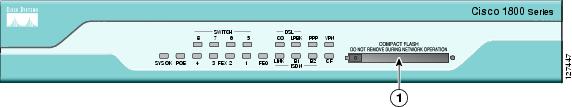
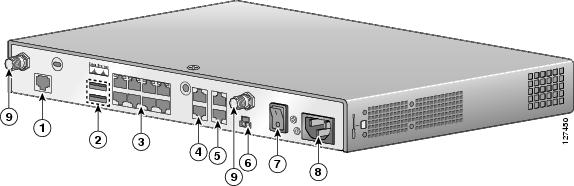
Figure 1-3 Front Panel of Cisco 1801 Router
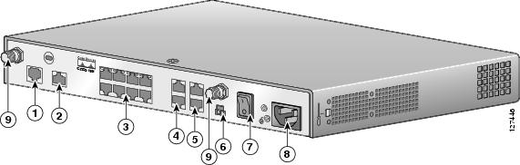
Figure 1-4 Back Panel of Cisco 1801 Router
ADSL over POTS WAN port
POE connector1
ISDN BRI S/T port
Power switch
Managed 8-port FE switch
Power connector
FE WAN port2
RP-TNC antenna connectors (wireless models only)
Console and AUX ports
1 Inline power is a field-upgradable option only. It is not installed by default.
2 The Cisco 1801 only has one FE WAN port, which is the lower of the two ports shown. The upper port is disabled, and reserved for a future purpose.
Figure 1-5 Front Panel of Cisco 1802 Router
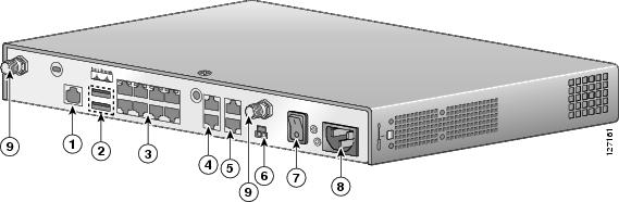
Figure 1-6 Back Panel of Cisco 1802 Router
ADSL over ISDN WAN port
POE connector1
ISDN BRI S/T port
Power switch
Managed 8-port FE switch
Power connector
FE WAN port2
RP-TNC antenna connectors (wireless models only)
Console and AUX ports
1 Inline power is a field-upgradable option only. It is not installed by default.
2 The Cisco 1802 only has one FE WAN port, which is the lower of the two ports shown. The upper port is disabled, and reserved for a future purpose.
Figure 1-7 Front Panel of Cisco 1803 Router
Figure 1-8 Back Panel of Cisco 1803 Router
G.SHDSL WAN port
POE connector1
ISDN BRI S/T port
Power switch
Managed 8-port FE switch
Power connector
FE WAN port2
RP-TNC antenna connectors (wireless models only)
Console and AUX ports
1 Inline power is a field-upgradable option only. It is not installed by default.
2 The Cisco 1803 only has one FE WAN port, which is the lower of the two ports shown. The upper port is disabled, and reserved for a future purpose.
Cisco 1811 Chassis
Figure 1-9 shows the front panel of a Cisco 1811 router. Figure 1-10 shows the rear panel of a Cisco 1811 router.
Figure 1-9 Front Panel of Cisco 1811 Router
Figure 1-10 Back Panel of Cisco 1811 Router
V.92 Modem port
POE connector1
USB 2.0 ports
Power switch
Managed 8-port FE switch
Power connector
FE WAN ports
RP-TNC antenna connectors (wireless models only)
Console and AUX ports
1 Inline power is a field-upgradable option only. It is not installed by default.
Cisco 1812 Chassis
Figure 1-11 shows the front panel of a Cisco 1812 router. Figure 1-12 shows the back panel of a Cisco 1812 router.
Figure 1-11 Front Panel of Cisco 1812 Router
Figure 1-12 Back Panel of Cisco 1812 Router
ISDN BRI S/T port
POE connector1
USB 2.0 ports
Power switch
Managed 8-port FE switch
Power connector
FE WAN ports
RP-TNC antenna connectors (wireless models only)
Console and AUX ports
1 Inline power is a field-upgradable option only. It is not installed by default.
Interface Numbering
The WAN and LAN interfaces on a Cisco 1800 series fixed-configuration router are numbered as follows:
•
•
•
•
•
•
Specifications
Table 1-5 provides the specifications for Cisco 1800 series fixed-configuration routers.
Table 1-5 Specifications for Cisco 1800 Series Fixed-Configuration Routers
Dimensions (W x D)
12.5 x 9.5 in. (31.75 x 24.13 cm)
Height without rubber feet: 1.73 in. (4.39 cm)
Height with rubber feet: 1.87 in. (4.75 cm)
Weight
Maximum: 6.1 lb (2.8 kg)
AC input power
Input voltage
Frequency
Input current
Inrush surge current
74 W maximum
100 to 240 VAC
50 or 60 Hz
1.2 to 0.6 A
50 A maximum, one cycle (-48V power included)
Power dissipation (maximum)
153 BTU/hr
Console and auxiliary ports
RJ-45 connector
Operating humidity
10 to 85% noncondensing operating; 5 to 95% noncondensing, nonoperating
Operating temperature
32 to 104×F (0 to 40×C)
Nonoperating temperature
-4 to 149×F (-20 to 65×C)
Noise level
<78° F/25.6°C: 34 dBA
>78°F/25.6°C through <104°F/40°C: 37 dBA
>104°F/40°C: 42 dBASafety compliance
UL 60950; CAN/CSA C22.2 No. 60950; IEC 60950-1; EN 60950-1; AS/NZS 60950
For detailed compliance information, see the Regulatory Compliance and Safety Information for Cisco 1800 Integrated Services Routers (Fixed) document.
EMC Immunity compliance
EN300386; EN55024(CISPR24); EN61000-4-2; EN61000-4-3; EN61000-4-4; EN61000-4-5; EN61000-4-6; EN61000-4-8; EN61000-4-11; EN55082-1; EN61000-6-2; ITU-T K.21
For detailed compliance information, see the Regulatory Compliance and Safety Information for Cisco 1800 Integrated Services Routers (Fixed) document.
EMC Emissions compliance
CFR 47 Part 15, Class A; ICES-003 Class A; EN55022 Class A; CISPR22 Class A; AS/NZS 3548 Class A; VCCI Class A; EN 300386; EN61000-3-2; EN61000-3-3
For detailed compliance information, see the Regulatory Compliance and Safety Information for Cisco 1800 Integrated Services Routers (Fixed) document.
Regulatory Compliance
For compliance information, see the Regulatory Compliance and Safety Information for Cisco 1800 Integrated Services Routers (Fixed) document that accompanied the router shipment.