-
Cisco 7600 Series Cisco IOS Software Configuration Guide, 12.2SR
-
Preface
-
Product Overview
-
Configuring the Router for the First Time
-
Configuring a Route Switch Processor 720
-
Configuring a Supervisor Engine 720
-
Configuring a Supervisor Engine 32
-
Configuring NSF with SSO Supervisor Engine Redundancy
-
Configuring RPR and RPR+ Supervisor Engine Redundancy
-
ISSU and eFSU on Cisco 7600 Series Routers
-
Configuring Interfaces
-
Configuring LAN Ports for Layer 2 Switching
-
Configuring Flex Links
-
Configuring EtherChannels
-
Configuring VTP
-
Configuring VLANs
-
Configuring Private VLANs
-
Configuring Cisco IP Phone Support
-
Configuring IEEE 802.1Q Tunneling
-
Configuring Layer 2 Protocol Tunneling
-
Configuring STP and MST
-
Configuring Optional STP Features
-
Configuring Layer 3 Interfaces
-
IP Subscriber Awareness over Ethernet
-
Configuring UDE and UDLR
-
Configuring Multiprotocol Label Switching on the PFC
-
Configuring IPv4 Multicast VPN Support
-
Configuring IP Unicast Layer 3 Switching
-
Configuring IPv6 Multicast PFC3 and DFC3 Layer 3 Switching
-
Configuring IPv4 Multicast Layer 3 Switching
-
Configuring MLDv2 Snooping for IPv6 Multicast Traffic
-
Configuring IGMP Snooping for IPv4 Multicast Traffic
-
Configuring PIM Snooping
-
Configuring Network Security
-
Understanding Cisco IOS ACL Support
-
Configuring VLAN ACLs
-
Private Hosts (Using PACLs)
-
Configuring Denial of Service Protection
-
Configuring DHCP Snooping
-
Configuring Dynamic ARP Inspection
-
Configuring Traffic Storm Control
-
Unknown Unicast Flood Blocking
-
Configuring PFC QoS
-
Configuring MPLS QoS on the PFC
-
Configuring PFC QoS Statistics Data Export
-
Configuring IEEE 802.1X Port-Based Authentication
-
Configuring Port Security
-
Configuring UDLD
-
Configuring NetFlow and NDE
-
Configuring Local SPAN, RSPAN, and ERSPAN
-
Configuring SNMP IfIndex Persistence
-
Power Management and Environmental Monitoring
-
Configuring Online Diagnostics
-
Configuring Web Cache Services Using WCCP
-
Using the Top N Utility
-
Using the Layer 2 Traceroute Utility
-
Using the Mini Protocol Analyzer
-
Online Diagnostic Tests
-
Configuring Call Home
-
Acronyms
-
Cisco IOS Release 12.2SRB Software Images
-
 Feedback
Table Of Contents
Configuring IGMP Snooping for IPv4 Multicast Traffic
Understanding How IGMP Snooping Works
Understanding the IGMP Snooping Querier
Understanding IGMP Version 3 Support
IGMP Version 3 Support Overview
Default IGMP Snooping Configuration
IGMP Snooping Configuration Guidelines and Restrictions
IGMP Snooping Querier Configuration Guidelines and Restrictions
Enabling the IGMP Snooping Querier
Configuring a Static Connection to a Multicast Receiver
Configuring a Multicast Router Port Statically
Configuring the IGMP Snooping Query Interval
Enabling IGMP Fast-Leave Processing
Configuring Source Specific Multicast (SSM) Mapping
Configuring IGMPv3 Explicit Host Tracking
Displaying IGMP Snooping Information
Displaying Multicast Router Interfaces
Displaying MAC Address Multicast Entries
Displaying IGMP Snooping Information for a VLAN Interface
Displaying IGMP Snooping Statistics
Configuring IGMP Snooping for IPv4 Multicast Traffic
This chapter describes how to configure Internet Group Management Protocol (IGMP) snooping for IPv4 multicast traffic on the Cisco 7600 series routers.
Note
•
http://www.cisco.com/en/US/products/hw/routers/ps368/prod_command_reference_list.html
•
This chapter consists of these sections:
•
•
•
•
•
Understanding How IGMP Snooping Works
These sections describe IGMP snooping:
•
•
IGMP Snooping Overview
You can configure the router to use IGMP snooping in subnets that receive IGMP queries from either IGMP or the IGMP snooping querier. IGMP snooping constrains IPv4 multicast traffic at Layer 2 by configuring Layer 2 LAN ports dynamically to forward IPv4 multicast traffic only to those ports that want to receive it.
IGMP, which runs at Layer 3 on a multicast router, generates Layer 3 IGMP queries in subnets where the multicast traffic needs to be routed. For information about IGMP, see Chapter 28, "Configuring IPv4 Multicast Layer 3 Switching."
You can configure the IGMP snooping querier on the router to support IGMP snooping in subnets that do not have any multicast router interfaces. For more information about the IGMP snooping querier, see the "Enabling the IGMP Snooping Querier" section.
IGMP (on a multicast router) or the IGMP snooping querier (on the supervisor engine) sends out periodic general IGMP queries that the router forwards through all ports in the VLAN and to which hosts respond. IGMP snooping monitors the Layer 3 IGMP traffic.
Note
Joining a Multicast Group
Hosts join multicast groups either by sending an unsolicited IGMP join message or by sending an IGMP join message in response to a general query from a multicast router (the router forwards general queries from multicast routers to all ports in a VLAN).
In response to an IGMP join request, the router creates an entry in its Layer 2 forwarding table for the VLAN on which the join request was received. When other hosts that are interested in this multicast traffic send IGMP join requests, the router adds them to the existing Layer 2 forwarding table entry. The router creates only one entry per VLAN in the Layer 2 forwarding table for each multicast group for which it receives an IGMP join request.
IGMP snooping suppresses all but one of the host join messages per multicast group and forwards this one join message to the multicast router.
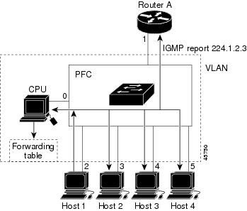
The router forwards multicast traffic for the multicast group specified in the join message to the interfaces where join messages were received (see Figure 30-1).
Layer 2 multicast groups learned through IGMP snooping are dynamic. However, you can statically configure Layer 2 multicast groups using the mac-address-table static command. When you specify group membership for a multicast group address statically, the static setting supersedes any IGMP snooping learning. Multicast group membership lists can consist of both static and IGMP snooping-learned settings.
Figure 30-1 Initial IGMP Join Message
Multicast router A sends a general query to the router, which forwards the query to ports 2 through 5 (all members of the same VLAN). Host 1 wants to join multicast group 224.1.2.3 and multicasts an IGMP membership report (IGMP join message) to the group with the equivalent MAC destination address of 0x0100.5E01.0203. When the CPU receives the IGMP report multicast by Host 1, the CPU uses the information in the IGMP report to set up a forwarding-table entry, as shown in Table 30-1, that includes the port numbers of Host 1, the multicast router, and the router internal CPU.
Table 30-1 IGMP Snooping Forwarding Table
0100.5exx.xxxx
IGMP
0
0100.5e01.0203
!IGMP
1, 2
The router hardware can distinguish IGMP information packets from other packets for the multicast group. The first entry in the table tells the switching engine to send only IGMP packets to the CPU. This prevents the CPU from becoming overloaded with multicast frames. The second entry tells the switching engine to send frames addressed to the 0x0100.5E01.0203 multicast MAC address that are not IGMP packets (!IGMP) to the multicast router and to the host that has joined the group.
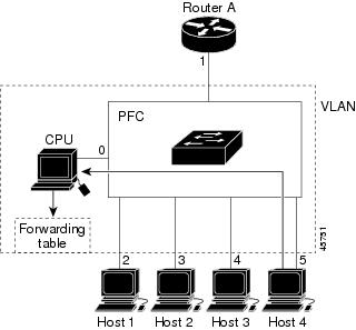
If another host (for example, Host 4) sends an unsolicited IGMP join message for the same group (Figure 30-2), the CPU receives that message and adds the port number of Host 4 to the forwarding table as shown in Table 30-2. Because the forwarding table directs IGMP messages only to the CPU, the message is not flooded to other ports. Any known multicast traffic is forwarded to the group and not to the CPU.
Figure 30-2 Second Host Joining a Multicast Group
Table 30-2 Updated IGMP Snooping Forwarding Table
0100.5exx.xxxx
IGMP
0
0100.5e01.0203
!IGMP
1, 2, 5
Leaving a Multicast Group
These sections describe leaving a multicast group:
Normal Leave Processing
Interested hosts must continue to respond to the periodic general IGMP queries. As long as at least one host in the VLAN responds to the periodic general IGMP queries, the multicast router continues forwarding the multicast traffic to the VLAN. When hosts want to leave a multicast group, they can either ignore the periodic general IGMP queries (called a "silent leave"), or they can send a group-specific IGMPv2 leave message.
When IGMP snooping receives a group-specific IGMPv2 leave message from a host, it sends out a MAC-based general query to determine if any other devices connected to that interface are interested in traffic for the specific multicast group. If IGMP snooping does not receive an IGMP Join message in response to the general query, it assumes that no other devices connected to the interface are interested in receiving traffic for this multicast group, and it removes the interface from its Layer 2 forwarding table entry for that multicast group. If the leave message was from the only remaining interface with hosts interested in the group and IGMP snooping does not receive an IGMP Join in response to the general query, it removes the group entry and relays the IGMP leave to the multicast router. If the multicast router receives no reports from a VLAN, the multicast router removes the group for the VLAN from its IGMP cache.
The interval for which the router waits before updating the table entry is called the "last member query interval." To configure the interval, enter the ip igmp snooping last-member-query-interval interval command.
Fast-Leave Processing
IGMP snooping fast-leave processing allows IGMP snooping to remove a Layer 2 LAN interface from the forwarding-table entry without first sending out IGMP group-specific queries to the interface. Upon receiving a group-specific IGMPv2 leave message, IGMP snooping immediately removes the interface from the Layer 2 forwarding table entry for that multicast group, unless a multicast router was learned on the port. Fast-leave processing improves bandwidth management for all hosts on a switched network.
Note
Understanding the IGMP Snooping Querier
Use the IGMP snooping querier to support IGMP snooping in a VLAN where PIM and IGMP are not configured because the multicast traffic does not need to be routed.
In a network where IP multicast routing is configured, the IP multicast router acts as the IGMP querier. If the IP-multicast traffic in a VLAN only needs to be Layer 2 switched, an IP-multicast router is not required, but without an IP-multicast router on the VLAN, you must configure another router as the IGMP querier so that it can send queries.
When enabled, the IGMP snooping querier sends out periodic IGMPv3 queries that trigger IGMP report messages from the router that wants to receive IP multicast traffic. IGMP snooping listens to these IGMP reports to establish appropriate forwarding.
You can enable the IGMP snooping querier on all the Cisco 7600 series routers in the VLAN, but for each VLAN that is connected to switches that use IGMP to report interest in IP multicast traffic, you must configure at least one router as the IGMP snooping querier.
You can configure a router to generate IGMP queries on a VLAN regardless of whether or not IP multicast routing is enabled.
Understanding IGMP Version 3 Support
These sections describe IGMP version 3 support:
•
IGMP Version 3 Support Overview
IGMP snooping supports IGMP version 3. IGMP version 3 uses source-based filtering, which enables hosts and routers to specify which source addresses should be allowed or blocked for a specific multicast group. When you enable IGMP version 3 snooping on a Cisco 7600 series router, the system maintains IGMP version 3 states based on messages it receives for a particular group in a particular VLAN and either allows or blocks traffic based on the following information in these messages:
•
•
Because the Layer 2 table is (MAC-group, VLAN) based, with IGMPv3 hosts it is preferable to have only a single multicast source per MAC-group.
Note
IGMPv3 Fast-Leave Processing
IGMP version 3 fast-leave processing is enabled by default. To disable IGMP version 3 fast-leave processing you must turn off explicit-host tracking.
Fast-leave processing with IGMPv3 is implemented by maintaining source-group based membership information in software while also allocating LTL indexes on a MAC GDA basis.
When fast-leave processing is enabled, hosts send BLOCK_OLD_SOURCES{src-list} messages for a specific group when they no longer want to receive traffic from that source. When the router receives such a message from a host, it parses the list of sources for that host for the given group. If this source list is exactly the same as the source list received in the leave message, the router removes the host from the LTL index and stops forwarding this multicast group traffic to this host.
If the source lists do not match, the router does not remove the host from the LTL index until the host is no longer interested in receiving traffic from any source.
Proxy Reporting
IGMP supports proxy reporting for IGMPv1 and IGMPv2 messages to handle group-specific queries. These queries are not sent downstream, but the switch does respond to them directly. When the switch recieves a group-specific query, the switch terminates the query and sends an IGMP proxy report if there is a receiver for the group. There is no proxy reporting for IGMPv3 messages. For IGMPv3, a group-specific query or a group source-specific query is flooded to all VLAN member ports. The database for the IGMPv3 membership report is built based on the reports received.
Host reports responding to a specific query can be suppressed by the report suppression feature. Report suppression is supported for IGMPv1, IGMPv2 and IGMPv3 messages. With report suppression enabled (by default), when the switch recieves a general query, the switch starts a suppression cycle for reports from all hosts to each group or channel (S,G). Only the first report to the discovered multicast routers are forwarded; the rest of the reports are suppressed. For IGMPv1 and IGMPv2, the time of suppression is the report response time indicated in the general query message. For IGMPv3, suppression occurs for the entire general query interval.
Note
•
Explicit Host Tracking
IGMPv3 supports explicit tracking of membership information on any port. The explicit-tracking database is used for fast-leave processing for IGMPv3 hosts, proxy reporting, and statistics collection. When explicit tracking is enabled on a VLAN, the IGMP snooping software processes the IGMPv3 report it receives from a host and builds an explicit-tracking database that contains the following information:
•
•
•
•
•
•
Note
•
Default IGMP Snooping Configuration
Table 30-3 shows the default IGMP snooping configuration.
IGMP Snooping Configuration Guidelines and Restrictions
When configuring IGMP snooping, follow these guidelines and restrictions:
•
http://www.cisco.com/univercd/cc/td/doc/product/software/ios122/122cgcr/fipr_c/ipcpt3/1cfmulti.htm
•
•
•
•
IGMP Snooping Querier Configuration Guidelines and Restrictions
When configuring the IGMP snooping querier, follow these guidelines and restrictions:
•
•
•
•
•
•
•
•
•
Note
Enabling the IGMP Snooping Querier
Use the IGMP snooping querier to support IGMP snooping in a VLAN where PIM and IGMP are not configured because the multicast traffic does not need to be routed.
To enable the IGMP snooping querier in a VLAN, perform this task:
This example shows how to enable the IGMP snooping querier on VLAN 200 and verify the configuration:
Router# interface vlan 200Router(config-if)# ip address 172.20.52.106 255.255.255.248Router(config-if)# igmp snooping querierRouter(config-if)# endRouter# show ip igmp interface vlan 200 | include querierIGMP snooping querier is enabled on this interfaceRouter#Configuring IGMP Snooping
Note
IGMP snooping allows Cisco 7600 series routers to examine IGMP packets and make forwarding decisions based on their content.
These sections describe how to configure IGMP snooping:
•
•
•
•
•
•
•
Note
Enabling IGMP Snooping
To enable IGMP snooping globally, perform this task:
This example shows how to enable IGMP snooping globally and verify the configuration:
Router(config)# ip igmp snoopingRouter(config)# endRouter# show ip igmp interface vlan 200 | include globallyIGMP snooping is globally enabledRouter#To enable IGMP snooping in a VLAN, perform this task:
This example shows how to enable IGMP snooping on VLAN 25 and verify the configuration:
Router# interface vlan 25Router(config-if)# ip igmp snoopingRouter(config-if)# endRouter# show ip igmp interface vl25 | include snoopingIGMP snooping is globally enabledIGMP snooping is enabled on this interfaceIGMP snooping fast-leave is disabled and querier is disabledIGMP snooping explicit-tracking is enabled on this interfaceIGMP snooping last member query interval on this interface is 1000 msRouter#Configuring a Static Connection to a Multicast Receiver
To configure a static connection to a multicast receiver, perform this task:
Step 1
Router(config)# mac-address-table static mac_addr vlan vlan_id interface type1 slot/port [disable-snooping]
Configures a static connection to a multicast receiver.
Router(config)# no mac-address-table static mac_addr vlan vlan_id
Clears a static connection to a multicast receiver.
Step 2
Router(config-if)# end
Exits configuration mode.
Step 3
Router# show mac-address-table address mac_addr
Verifies the configuration.
1 type = ethernet, fastethernet, gigabitethernet, or tengigabitethernet
When you configure a static connection, enter the disable-snooping keyword to prevent multicast traffic addressed to the statically configured multicast MAC address from also being sent to other ports in the same VLAN.
This example shows how to configure a static connection to a multicast receiver:
Router(config)# mac-address-table static 0050.3e8d.6400 vlan 12 interface fastethernet 5/7Configuring a Multicast Router Port Statically
To configure a static connection to a multicast router, perform this task:
Step 1
Router(config-if)# ip igmp snooping mrouter interface type1 slot/port
Configures a static connection to a multicast router.
Step 2
Router(config-if)# end
Exits configuration mode.
Step 3
Router# show ip igmp snooping mrouter
Verifies the configuration.
1 type = ethernet, fastethernet, gigabitethernet, or tengigabitethernet
The interface to the router must be in the VLAN where you are entering the command, the interface must be administratively up, and the line protocol must be up.
This example shows how to configure a static connection to a multicast router:
Router(config-if)# ip igmp snooping mrouter interface fastethernet 5/6Router(config-if)#Configuring the IGMP Snooping Query Interval
You can configure the interval for which the router waits after sending a group-specific query to determine if hosts are still interested in a specific multicast group.
Note
To configure the interval for the IGMP snooping queries sent by the router, perform this task:
This example shows how to configure the IGMP snooping query interval:
Router(config-if)# ip igmp snooping last-member-query-interval 200Router(config-if)# exitRouter# show ip igmp interface vlan 200 | include lastIGMP snooping last member query interval on this interface is 200 msEnabling IGMP Fast-Leave Processing
To enable IGMP fast-leave processing in a VLAN, perform this task:
This example shows how to enable IGMP fast-leave processing on the VLAN 200 interface and verify the configuration:
Router# interface vlan 200Router(config-if)# ip igmp snooping fast-leaveConfiguring fast leave on vlan 200Router(config-if)# endRouter# show ip igmp interface vlan 200 | include fast-leaveIGMP snooping fast-leave is enabled on this interfaceRouter(config-if)#Configuring Source Specific Multicast (SSM) Mapping
Note
To configure SSM mapping, refer to this publication:
http://www.cisco.com/univercd/cc/td/doc/product/software/ios123/123newft/123t/123t_2/gtssmma.htm
Enabling SSM Safe Reporting
Note
When you configure SSM safe reporting, the group mode is IGMPv3 even in the presence of IGMPv1 and IGMPv2 hosts.
To make sure the router is able to support both IGMPv1, IGMPv2, and IGMPv3 hosts in the same VLAN, perform this task:
This example shows how to configure the router to support both IGMPv2 and IGMPv3 hosts:
Router(config)# interface vlan 10Router(config-if)# ip igmp snooping ssm-safe-reportingConfiguring IGMPv3 Explicit Host Tracking
To enable explicit host tracking on a VLAN, perform this task:
This example shows how to enable explicit host tracking:
Router(config)# interface vlan 25Router(config-if)# ip igmp snooping explicit-trackingRouter(config-if)# endRouter# show ip igmp snooping explicit-tracking vlan 25Source/Group Interface Reporter Filter_mode------------------------------------------------------------------------10.1.1.1/226.2.2.2 Vl25:1/2 16.27.2.3 INCLUDE10.2.2.2/226.2.2.2 Vl25:1/2 16.27.2.3 INCLUDEDisplaying IGMP Snooping Information
These sections describe displaying IGMP snooping information:
•
•
•
•
Displaying Multicast Router Interfaces
When you enable IGMP snooping, the router automatically learns to which interface the multicast routers are connected.
To display multicast router interfaces, perform this task:
This example shows how to display the multicast router interfaces in VLAN 1:
Router# show ip igmp snooping mrouter vlan 1vlan ports-----+----------------------------------------1 Gi1/1,Gi2/1,Fa3/48,RouterRouter#Displaying MAC Address Multicast Entries
To display MAC address multicast entries for a VLAN, perform this task:
Router# show mac-address-table multicast vlan_ID [count]
Displays MAC address multicast entries for a VLAN.
This example shows how to display MAC address multicast entries for VLAN 1:
Router# show mac-address-table multicast vlan 1vlan mac address type qos ports-----+---------------+--------+---+--------------------------------1 0100.5e02.0203 static -- Gi1/1,Gi2/1,Fa3/48,Router1 0100.5e00.0127 static -- Gi1/1,Gi2/1,Fa3/48,Router1 0100.5e00.0128 static -- Gi1/1,Gi2/1,Fa3/48,Router1 0100.5e00.0001 static -- Gi1/1,Gi2/1,Fa3/48,Router,SwitchRouter#This example shows how to display a total count of MAC address entries for a VLAN:
Router# show mac-address-table multicast 1 countMulticast MAC Entries for vlan 1: 4Router#Displaying IGMP Snooping Information for a VLAN Interface
To display IGMP snooping information for a VLAN interface, perform this task:
Router# show ip igmp interface vlan_ID
Displays IGMP snooping information on a VLAN interface.
This example shows how to display IGMP snooping information on the VLAN 200 interface:
Router# show ip igmp interface vlan 43Vlan43 is up, line protocol is upInternet address is 43.0.0.1/24IGMP is enabled on interfaceCurrent IGMP host version is 2Current IGMP router version is 2IGMP query interval is 60 secondsIGMP querier timeout is 120 secondsIGMP max query response time is 10 secondsLast member query count is 2Last member query response interval is 1000 msInbound IGMP access group is not setIGMP activity:1 joins, 0 leavesMulticast routing is enabled on interfaceMulticast TTL threshold is 0Multicast designated router (DR) is 43.0.0.1 (this system)IGMP querying router is 43.0.0.1 (this system)Multicast groups joined by this system (number of users):224.0.1.40(1)IGMP snooping is globally enabledIGMP snooping is enabled on this interfaceIGMP snooping fast-leave is disabled and querier is disabledIGMP snooping explicit-tracking is enabled on this interfaceIGMP snooping last member query interval on this interface is 1000 msRouter#Displaying IGMP Snooping Statistics
The show ip igmp snooping statistics interface vlan_ID command displays the following information:
•
•
•
•
To display IGMP snooping statistics, perform this task:
Router# show ip igmp snooping statistics interface vlan_ID
Displays IGMP snooping information on a VLAN interface.
This example shows IGMP snooping statistics information for interface VLAN 25:
Router# show ip igmp snooping statistics interface vlan 25Snooping statistics for Vlan25#channels:2#hosts :1Source/Group Interface Reporter Uptime Last-Join Last-Leave10.1.1.1/226.2.2.2 Gi1/2:Vl25 16.27.2.3 00:01:47 00:00:50 -10.2.2.2/226.2.2.2 Gi1/2:Vl25 16.27.2.3 00:01:47 00:00:50 -Router#Troubleshooting
This section describes how to troubleshoot common IGMP issues.