Downloads |
 Feedback Feedback
|
Table Of Contents
IEEE 802.1Q-in-Q VLAN Tag Termination
Prerequisites for IEEE 802.1Q-in-Q VLAN Tag Termination
Restrictions for IEEE 802.1Q-in-Q VLAN Tag Termination
Information About IEEE 802.1Q-in-Q VLAN Tag Termination
IEEE 802.1Q-in-Q VLAN Tag Termination on Subinterfaces
Cisco 10000 Series Router Application
Security ACL Application on the Cisco 10000 Series Router
Unambiguous and Ambiguous Subinterfaces
How to Configure IEEE 802.1Q-in-Q VLAN Tag Termination
Configuring the Interfaces for IEEE 802.1Q-in-Q VLAN Tag Termination
Verifying the IEEE 802.1Q-in-Q VLAN Tag Termination
Configuration Examples for IEEE 802.1Q-in-Q VLAN Tag Termination
Configuring any Keyword on Subinterfaces for IEEE 802.1Q-in-Q VLAN Tag Termination: Example
IEEE 802.1Q-in-Q VLAN Tag Termination
Encapsulating IEEE 802.1Q VLAN tags within 802.1Q enables service providers to use a single VLAN to support customers who have multiple VLANs. The IEEE 802.1Q-in-Q VLAN Tag Termination feature on the subinterface level preserves VLAN IDs and keeps traffic in different customer VLANs segregated.
Feature History for the IEEE 802.1Q-in-Q VLAN Tag Termination Feature
Finding Support Information for Platforms and Cisco IOS Software Images
Use Cisco Feature Navigator to find information about platform support and Cisco IOS software image support. Access Cisco Feature Navigator at http://www.cisco.com/go/fn. You must have an account on Cisco.com. If you do not have an account or have forgotten your username or password, click Cancel at the login dialog box and follow the instructions that appear.
Contents
•
Prerequisites for IEEE 802.1Q-in-Q VLAN Tag Termination
•
•
•
•
Prerequisites for IEEE 802.1Q-in-Q VLAN Tag Termination
•
•
Restrictions for IEEE 802.1Q-in-Q VLAN Tag Termination
Cisco 10000 Series Router Restrictions
•
•
•
•
•
•
•
•
•
•
Information About IEEE 802.1Q-in-Q VLAN Tag Termination
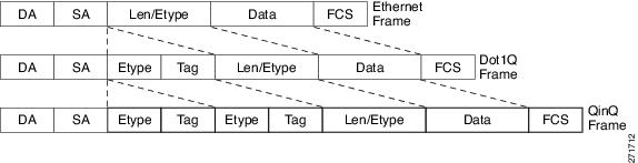
This Cisco IOS feature adds support for IP over IEEE 802.1QinQ (VLAN Tag stacking). QinQ encapsulation processing is an extension to 802.1q encapsulation processing. A QinQ frame looks like a VLAN 802.1Q frame, only it has two 802.1Q tags instead of one. Figure 1 demonstrates a QinQ frame.
Figure 1 QinQ frame
In releases prior to Cisco IOS Release 12.2(31)SB2, PRE2 supported PPPoEoQinQ encapsulation only. This capability has been retained and support is added for QinQ encapsulated IP traffic.
This section lists the concepts that the user should understand in order to perform the tasks in the "How to Configure IEEE 802.1Q-in-Q VLAN Tag Termination" section. The following concepts are described in this section:
•
•
•
IEEE 802.1Q-in-Q VLAN Tag Termination on Subinterfaces
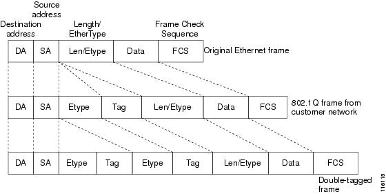
IEEE 802.1Q-in-Q VLAN Tag Termination simply adds another layer of IEEE 802.1Q tag (called "metro tag" or "PE-VLAN") to the 802.1Q tagged packets that enter the network. The purpose is to expand the VLAN space by tagging the tagged packets, thus producing a "double-tagged" frame. The expanded VLAN space allows the service provider to provide certain services, such as Internet access on specific VLANs for specific customers, and yet still allows the service provider to provide other types of services for their other customers on other VLANs.
Generally the service provider's customers require a range of VLANs to handle multiple applications. Service providers can allow their customers to use this feature to safely assign their own VLAN IDs on subinterfaces because these subinterface VLAN IDs are encapsulated within a service provider-designated VLAN ID for that customer. Therefore there is no overlap of VLAN IDs among customers, nor does traffic from different customers become mixed. The double-tagged frame is "terminated" or assigned on a subinterface with an expanded encapsulation dot1q command that specifies the two VLAN ID tags (outer VLAN ID and inner VLAN ID) terminated on the subinterface. See Figure 2.
IEEE 802.1Q-in-Q VLAN Tag Termination is generally supported on whichever Cisco IOS features or protocols are supported on the subinterface. For example, if you can run PPPoE on the subinterface, you can configure a double-tagged frame for PPPoE. IPoQ-in-Q supports IP packets that are double-tagged for Q-in-Q VLAN tag termination by forwarding IP traffic with the double-tagged (also known as stacked) 802.1Q headers.
A primary consideration is whether you assign ambiguous or unambiguous subinterfaces for the inner VLAN ID. See the "Unambiguous and Ambiguous Subinterfaces" section.
For information on supported PPPoE sessions, number of supported inner and outer VLAN IDs, and general restrictions on the Cisco 10000 series routers, see Restrictions for IEEE 802.1Q-in-Q VLAN Tag Termination.
Note
The primary benefit for the service provider is reduced number of VLANs supported for the same number of customers. Other benefits of this feature include:
•
Note
•
The Q-in-Q VLAN tag termination feature is simpler than the IEEE 802.1Q tunneling feature deployed for the Catalyst 6500 series switches or the Catalyst 3550 and Catalyst 3750 switches. Whereas switches require IEEE 802.1Q tunnels on interfaces to carry double-tagged traffic, routers need only encapsulate Q-in-Q VLAN tags within another level of 802.1Q tags in order for the packets to arrive at the correct destination.
Figure 2 Untagged, 802.1Q-Tagged, and Double-Tagged Ethernet Frames
Cisco 10000 Series Router Application
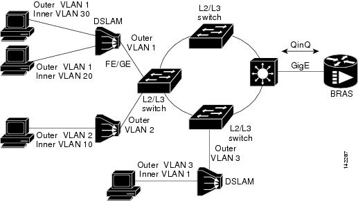
For the emerging broadband Ethernet-based DSLAM market, the Cisco 10000 series router supports Q-in-Q encapsulation. With the Ethernet-based DSLAM model shown in Figure 3, customers typically get their own VLAN and all these VLANs are aggregated on a DSLAM.
Figure 3
Broadband Ethernet-based DSLAM Model of Q-in-Q VLANs
VLAN aggregation on a DSLAM will result in a lot of aggregate VLANs that at some point need to be terminated on the broadband remote access servers (BRAS). Although the model could connect the DSLAMs directly to the BRAS, a more common model uses the existing Ethernet-switched network where each DSLAM VLAN ID is tagged with a second tag (Q-in-Q) as it connects into the Ethernet-switched network.
The Cisco 10000 series router supports PPPoEoQ-in-Q in Cisco IOS Release 12.3(7)XI1 and later, and IP over Q-in-Q (IPoQ-in-Q) in Cisco IOS Release 12.3(7)XI7 and later. Both PPPoE sessions and IP can be enabled on a subinterface. For information on supported PPPoE sessions, number of supported inner and outer VLAN IDs, and general restrictions on the Cisco 10000 series router, see the "Restrictions for IEEE 802.1Q-in-Q VLAN Tag Termination" section.
The PPPoEoQ-in-Q model is a PPP-terminated session.
PPPoQ-in-Q and IPoQ-in-Q encapsulation processing is an extension to 802.1Q encapsulation processing. A Q-in-Q frame looks like a VLAN 802.1Q frame, only it has two 802.1Q tags instead of one. See Figure 2.
Q-in-Q encapsulation supports configurable outer tag Ethertype. The configurable Ethertype field values are 0x8100 (default), 0x9100, and 0x9200. See Figure 4.
Figure 4
Supported Configurable Ethertype Field Values
Security ACL Application on the Cisco 10000 Series Router
The IEEE 802.1Q-in-Q VLAN Tag Termination feature provides limited security access control list (ACL) support for PPPoEoQ-in-Q subinterfaces for the Cisco 10000 series router. There are no ACL restrictions on subinterfaces configured with IPoQ-in-Q.
If you apply an ACL to PPPoE traffic on a Q-in-Q subinterface in a VLAN, apply the ACL directly on the PPPoE session, using virtual access interfaces (VAIs) or RADIUS attribute 11 or 242.
You can apply ACLs to virtual access interfaces by configuring them under virtual template interfaces. You can also configure ACLs by using RADIUS attribute 11 or 242. When you use attribute 242, a maximum of 30,000 sessions can have ACLs.
ACLs that are applied to the VLAN Q-in-Q subinterface have no effect and are silently ignored. In the following example, ACL 1 that is applied to the VLAN Q-in-Q subinterface level will be ignored:
Router(config)# interface FastEthernet3/0/0.100Router(config-subif)# encapsulation dot1q 100 second-dot1q 200Router(config-subif)# ip access-group 1Unambiguous and Ambiguous Subinterfaces
Note
The encapsulation dot1q command is used to configure Q-in-Q termination on a subinterface. The command accepts an outer VLAN ID and one or more inner VLAN IDs. The outer VLAN ID always has a specific value, while the inner VLAN ID can either be a specific value or a range of values.
A subinterface that is configured with a single inner VLAN ID is called an unambiguous Q-in-Q subinterface. In the following example, Q-in-Q traffic with an outer VLAN ID of 101 and an inner VLAN ID of 1001 is mapped to the Gigabit Ethernet 1/0.100 subinterface:
Router(config)# interface gigabitEehernet1/0.100Router(config-subif)# encapsulation dot1q 101 second-dot1q 1001A subinterface that is configured with multiple inner VLAN IDs is called an ambiguous Q-in-Q subinterface. By allowing multiple inner VLAN IDs to be grouped together, ambiguous Q-in-Q subinterfaces allow for a smaller configuration, improved memory usage, and better scalability.
In the following example, Q-in-Q traffic with an outer VLAN ID of 101 and inner VLAN IDs anywhere in the 2001-2100 and 3001-3100 range is mapped to the Gigabit Ethernet 1/0.101 subinterface.:
Router(config)# interface gigabitethernet1/0.101Router(config-subif)# encapsulation dot1q 101 second-dot1q 2001-2100,3001-3100Ambiguous subinterfaces can also use the any keyword to specify the inner VLAN ID.
See the "Configuration Examples for IEEE 802.1Q-in-Q VLAN Tag Termination" section for an example of how VLAN IDs are assigned to subinterfaces, and for a detailed example of how the any keyword is used on ambiguous subinterfaces.
Note
Note
How to Configure IEEE 802.1Q-in-Q VLAN Tag Termination
This section contains the following tasks:
•
•
Configuring the Interfaces for IEEE 802.1Q-in-Q VLAN Tag Termination
Perform this task to configure the main interface used for the Q-in-Q double tagging and to configure the subinterfaces. An optional step in this task shows you how to configure the Ethertype field to be 0x9100 for the outer VLAN tag, if that is required. After the subinterface is defined, the 802.1Q encapsulation is configured to use the double tagging.
Prerequisites
Cisco 10000 Series Router Prerequisites:
•
•
SUMMARY STEPS
Steps to configure Ethertype field for outer VLAN tag (Optional):
1.
2.
3.
4.
Steps to configure the Q-in-Q subinterface:
5.
6.
7.
8.
9.
10.
11.
DETAILED STEPS
Verifying the IEEE 802.1Q-in-Q VLAN Tag Termination
Perform this optional task to verify the configuration of the IEEE 802.1Q-in-Q VLAN Tag Termination feature.
SUMMARY STEPS
1.
2.
3.
DETAILED STEPS
Step 1
Enables privileged EXEC mode. Enter your password if prompted.
Router> enableStep 2
Use this command to show the currently running configuration on the device. You can use delimiting characters to display only the relevant parts of the configuration.
The following shows the currently running PPPoEoQ-in-Q and IPoQ-in-Q configurations on a Cisco 10000 series router:
Router# show running-config...interface FastEthernet0/0.201encapsulation dot1Q 201ip address 10.7.7.5 255.255.255.252!interface FastEthernet0/0.401encapsulation dot1Q 401ip address 10.7.7.13 255.255.255.252!interface FastEthernet0/0.201999encapsulation dot1Q 201 second-dot1q anypppoe enable!interface FastEthernet0/0.2012001encapsulation dot1Q 201 second-dot1q 2001ip address 10.8.8.9 255.255.255.252!interface FastEthernet0/0.2012002encapsulation dot1Q 201 second-dot1q 2002ip address 10.8.8.13 255.255.255.252pppoe enable!interface FastEthernet0/0.4019999encapsulation dot1Q 401 second-dot1q 100-900,1001-2000pppoe enable!interface GigabitEthernet5/0.101encapsulation dot1Q 101ip address 10.7.7.1 255.255.255.252!interface GigabitEthernet5/0.301encapsulation dot1Q 301ip address 10.7.7.9 255.255.255.252!interface GigabitEthernet5/0.301999encapsulation dot1Q 301 second-dot1q anypppoe enable!interface GigabitEthernet5/0.1011001encapsulation dot1Q 101 second-dot1q 1001ip address 10.8.8.1 255.255.255.252!interface GigabitEthernet5/0.1011002encapsulation dot1Q 101 second-dot1q 1002ip address 10.8.8.5 255.255.255.252!interface GigabitEthernet5/0.1019999encapsulation dot1Q 101 second-dot1q 1-1000,1003-2000pppoe enable...Step 3
Use this command to show the statistics for all the 802.1Q VLAN IDs. In this example, only the outer VLAN ID is displayed.
Note
Router# show vlans dot1qTotal statistics for 802.1Q VLAN 1:441 packets, 85825 bytes input1028 packets, 69082 bytes outputTotal statistics for 802.1Q VLAN 101:5173 packets, 510384 bytes input3042 packets, 369567 bytes outputTotal statistics for 802.1Q VLAN 201:1012 packets, 119254 bytes input1018 packets, 120393 bytes outputTotal statistics for 802.1Q VLAN 301:3163 packets, 265272 bytes input1011 packets, 120750 bytes outputTotal statistics for 802.1Q VLAN 401:1012 packets, 119254 bytes input1010 packets, 119108 bytes output
Configuration Examples for IEEE 802.1Q-in-Q VLAN Tag Termination
This section contains the following example:
•
Configuring any Keyword on Subinterfaces for IEEE 802.1Q-in-Q VLAN Tag Termination: Example
Some ambiguous subinterfaces can use the any keyword for the inner VLAN ID specification. The any keyword represents any inner VLAN ID that is not explicitly configured on any other interface. In the following example, seven subinterfaces are configured with various outer and inner VLAN IDs.
Note
Note
interface GigabitEthernet1/0/0.1encapsulation dot1q 100 second-dot1q 100interface GigabitEthernet1/0/0.2encapsulation dot1q 100 second-dot1q 200interface GigabitEthernet1/0/0.3encapsulation dot1q 100 second-dot1q 300-400,500-600interface GigabitEthernet1/0/0.4encapsulation dot1q 100 second-dot1q anyinterface GigabitEthernet1/0/0.5encapsulation dot1q 200 second-dot1q 50interface GigabitEthernet1/0/0.6encapsulation dot1q 200 second-dot1q 1000-2000,3000-4000interface GigabitEthernet1/0/0.7encapsulation dot1q 200 second-dot1q anyTable 1 shows which subinterfaces are mapped to different values of the outer and inner VLAN IDs on Q-in-Q frames that come in on Gigabit Ethernet interface 1/0/0.
A new subinterface is now configured:
interface GigabitEthernet1/0/0.8encapsulation dot1q 200 second-dot1q 200-600,900-999Table 2 shows the changes made to the table for the outer VLAN ID of 200. Notice that subinterface 1/0/0.7 configured with the any keyword now has new inner VLAN ID mappings.
Additional References
The following sections provide references related to the IEEE 802.1Q-in-Q VLAN Tag Termination feature.
Related Documents
Interface commands: complete command syntax, command mode, defaults, usage guidelines, and examples
Cisco IOS Interface and Hardware Component Command Reference, Release 12.3T
Interface configuration examples
Cisco IOS Interface and Hardware Component Configuration Guide
Standards
MIBs
RFCs
No new or modified RFCs are supported by this feature, and support for existing RFCs has not been modified by this feature.
—
Technical Assistance
Command Reference
This section documents the following commands.
dot1q tunneling ethertype
To define the Ethertype field type used by peer devices when implementing Q-in-Q VLAN tagging, use the dot1q tunneling ethertype command in interface configuration mode. To remove the VLAN tag Ethertype, use the no form of this command.
dot1q tunneling ethertype {0x8100 | 0x9100 | 0x9200}
no dot1q tunneling ethertype {0x8100 | 0x9100 | 0x9200}
Syntax Description
Defaults
The Ethertype field used by peer devices when implementing Q-in-Q VLAN tagging is 0x8100.
Command Modes
Interface configuration
Command History
Usage Guidelines
Use the dot1q tunneling ethertype command if the peer switching devices are using an Ethertype field value of 0x9100 or 0x9200. All Cisco switching devices use the default Ethertype field value of 0x8100. The Cisco 10000 series router additionally supports the 0x9200 Ethertype field value.
Note
This command is used with the IEEE 802.1Q-in-Q VLAN Tag Termination feature in which double VLAN tagging is configured using the encapsulation dot1q command. 802.1Q double tagging allows a service provider to use a single VLAN to support customers who have multiple VLANs.
Examples
The following example shows how to configure an Ethertype field as 0x9100:
Router(config)# interface gigabitethernet 1/0/0Router(config-if)# dot1q tunneling ethertype 0x9100The following example shows how to configure an Ethertype field as 0x9200 on a Cisco 10000 series router:
Router(config)# interface gigabitethernet 1/0/0Router(config-if)# dot1q tunneling ethertype 0x9200Related Commands
encapsulation dot1q
To enable IEEE 802.1Q encapsulation of traffic on a specified subinterface in a VLAN, use the encapsulation dot1q command in interface range configuration mode or subinterface configuration mode. To disable IEEE 802.1Q encapsulation, use the no form of this command.
Interface Range Configuration Mode
encapsulation dot1q vlan-id [native]
no encapsulation dot1q
Subinterface Configuration Mode
encapsulation dot1q vlan-id second-dot1q {any | vlan-id | vlan-id-vlan-id[,vlan-id-vlan-id]}
no encapsulation dot1q vlan-id second-dot1q {any | vlan-id | vlan-id-vlan-id[,vlan-id-vlan-id]}
Syntax Description
Defaults
IEEE 802.1Q encapsulation is disabled.
Command Modes
Interface range configuration
Subinterface configurationCommand History
Usage Guidelines
Interface Range Configuration Mode
IEEE 802.1Q encapsulation is configurable on Fast Ethernet interfaces. IEEE 802.1Q is a standard protocol for interconnecting multiple switches and routers and for defining VLAN topologies.
Use the encapsulation dot1q command in interface range configuration mode to apply a VLAN ID to each subinterface within the range specified by the interface range command. The VLAN ID specified by the vlan-id argument is applied to the first subinterface in the range. Each subsequent interface is assigned a VLAN ID, which is the specified vlan-id value plus the subinterface number minus the first subinterface number (VLAN ID + subinterface number - first subinterface number).
Note
Do not configure encapsulation on the native VLAN of an IEEE 802.1Q trunk without using the native keyword. (Always use the native keyword when vlan-id is the ID of the IEEE 802.1Q native VLAN.)
Subinterface Configuration Mode
Use the second-dot1q keyword to configure the IEEE 802.1Q-in-Q VLAN Tag Termination feature. 802.1Q in 802.1Q (Q-in-Q) VLAN tag termination adds another layer of 802.1Q tag (called "metro tag" or "PE-VLAN") to the 802.1Q tagged packets that enter the network. Double tagging expands the VLAN space, allowing service providers to offer certain services such as Internet access on specific VLANs for some customers and other types of services on other VLANs for other customers.
After a subinterface is defined, use the encapsulation dot1q command to add outer and inner VLAN ID tags to allow one VLAN to support multiple VLANs. You can assign a specific inner VLAN ID to the subinterface; that subinterface is unambiguous. Or you can assign a range or ranges of inner VLAN IDs to the subinterface; that subinterface is ambiguous.
Examples
The following example shows how to create the subinterfaces within the range 0.11 and 0.60 and apply VLAN ID 101 to the Fast Ethernet0/0.11 subinterface, VLAN ID 102 to Fast Ethernet0/0.12 (vlan-id = 101 + 12 - 11 = 102), and so on up to VLAN ID 150 to Fast Ethernet0/0.60 (vlan-id = 101 + 60 - 11 = 150):
Router(config)# interface range fastethernet0/0.11 - fastethernet0/0.60Router(config-int-range)# encapsulation dot1q 101The following example shows how to terminate a Q-in-Q frame on an unambiguous subinterface with an outer VLAN ID of 100 and an inner VLAN ID of 200:
Router(config)# interface gigabitethernet1/0/0.1Router(config-subif)# encapsulation dot1q 100 second-dot1q 200The following example shows how to terminate a Q-in-Q frame on an ambiguous subinterface with an outer VLAN ID of 100 and an inner VLAN ID in the range from 100 to 199 or from 201 to 600:
Router(config)# interface gigabitethernet1/0/0.1Router(config-subif)# encapsulation dot1q 100 second-dot1q 100-199,201-600Related Commands
show vlans dot1q
To display statistics about 802.1Q VLAN subinterfaces, use the show vlans dot1q command in privileged EXEC mode.
show vlans dot1q [internal | interface-type interface-number.subinterface-number [detail] | outer-id [interface-type interface-number | second-dot1q [inner-id | any]] [detail]]
Syntax Description
Command Modes
Privileged EXEC
Command History
Usage Guidelines
If no arguments or keywords are entered, statistics for all of the 802.1Q VLAN IDs are displayed.
The any keyword is not supported for IPoQinQ because IP routing is not supported on ambiguous subinterfaces. However, the second-dot1q inner-id keyword and argument can be used on IPoQinQ for a specific inner VLAN ID that is not an ambiguous subinterface.
Note
Examples
The output from the show vlans dot1q command displays the statistics for all the 802.1Q VLAN IDs. Only the outer VLAN IDs are displayed here.
Router# show vlans dot1qTotal statistics for 802.1Q VLAN 1:441 packets, 85825 bytes input1028 packets, 69082 bytes outputTotal statistics for 802.1Q VLAN 101:5173 packets, 510384 bytes input3042 packets, 369567 bytes outputTotal statistics for 802.1Q VLAN 201:1012 packets, 119254 bytes input1018 packets, 120393 bytes outputTotal statistics for 802.1Q VLAN 301:3163 packets, 265272 bytes input1011 packets, 120750 bytes outputTotal statistics for 802.1Q VLAN 401:1012 packets, 119254 bytes input1010 packets, 119108 bytes outputTable 3 describes the significant fields shown in the display.
The following sample output from the show vlans dot1q command displays the statistics for the 802.1Q VLAN subinterface configured on Gigabit Ethernet interface 5/0:
Router# show vlans dot1q GigabitEthernet 5/0.1011001GigabitEthernet5/0.1011001 (101/1001)1005 packets, 122556 bytes input1023 packets, 125136 bytes outputTable 4 describes the significant fields shown in the display.
The following sample output from the show vlans dot1q command displays the summary statistics for all of the VLAN subinterfaces under the physical interface Gigabit Ethernet 5/0 that have an outer VLAN ID of 101:
Router# show vlans dot1q 101 GigabitEthernet 5/0Total statistics for 802.1Q VLAN 101 on GigabitEthernet5/0:5218 packets, 513444 bytes input3042 packets, 369567 bytes outputThe following sample output from the show vlans dot1q command displays the individual subinterface statistics and summary statistics for all the VLAN subinterfaces under the physical interface Gigabit Ethernet 5/0 that have an outer VLAN ID of 101:
Router# show vlans dot1q 101 GigabitEthernet 5/0 detailGigabitEthernet5/0.101 (0)3220 packets, 269148 bytes input1008 packets, 119622 bytes outputGigabitEthernet5/0.1019999 (101/1-1000,1003-2000)0 packets, 0 bytes input3 packets, 1143 bytes outputGigabitEthernet5/0.1011001 (101/1001)1005 packets, 122556 bytes input1023 packets, 125136 bytes outputGigabitEthernet5/0.1011002 (101/1002)1005 packets, 122556 bytes input1008 packets, 123666 bytes outputTotal statistics for 802.1Q VLAN 101 on GigabitEthernet5/0:5230 packets, 514260 bytes input3042 packets, 369567 bytes outputThe following sample output from the show vlans dot1q command displays the statistics for an outer VLAN and inner VLAN ID combination. This is a summary that displays the total for all the subinterfaces on the router that are configured with the specified IDs.
Note
Router# show vlans dot1q 101 second-dot1q 1001 detailGigabitEthernet5/0.1011001 (101/1001)1005 packets, 122556 bytes input1023 packets, 125136 bytes outputTotal statistics for Outer/Inner VLAN 101/1001:1005 packets, 122556 bytes input1023 packets, 125136 bytes outputThe following sample output from the show vlans dot1q command displays the statistics for a specific outer VLAN ID of 301 and an inner VLAN ID of any. This is a summary that displays the total for all of the subinterfaces on the router that are configured with the specified IDs.
Router# show vlans dot1q 301 second-dot1q anyGigabitEthernet5/0.301999 (301/any)0 packets, 0 bytes input3 packets, 1128 bytes outputTotal statistics for Outer/Inner VLAN 301/"any":0 packets, 0 bytes input3 packets, 1128 bytes outputThe following sample output from the show vlans dot1q command displays some internal information about the QinQ subsystem and is used for troubleshooting purposes (typically by Cisco engineers):
Router# show vlans dot1q internalInternal VLAN representation on FastEthernet0/0:VLAN Id: 1 (.1Q, Fa0/0)VLAN Id: 201 (.1Q-in-.1Q tree, 3 elements)Inner VLAN Id: (0 -0 ) Fa0/0.201dot1q software subblock bitlist missingInner VLAN Id: (2001-2001) Fa0/0.20120012001Inner VLAN Id: (2002-2002) Fa0/0.20120022002"any" Fa0/0.201999VLAN Id: 401 (.1Q-in-.1Q tree, 3 elements)Inner VLAN Id: (0 -0 ) Fa0/0.401dot1q software subblock bitlist missingInner VLAN Id: (100 -900 ) Fa0/0.4019999100-900,1001-2000Inner VLAN Id: (1001-2000) Fa0/0.4019999100-900,1001-2000Internal VLAN representation on GigabitEthernet5/0:VLAN Id: 1 (.1Q, Gi5/0)VLAN Id: 101 (.1Q-in-.1Q tree, 5 elements)Inner VLAN Id: (0 -0 ) Gi5/0.101dot1q software subblock bitlist missingInner VLAN Id: (1 -1000) Gi5/0.10199991-1000,1003-2000Inner VLAN Id: (1001-1001) Gi5/0.10110011001Inner VLAN Id: (1002-1002) Gi5/0.10110021002Inner VLAN Id: (1003-2000) Gi5/0.10199991-1000,1003-2000VLAN Id: 301 (.1Q-in-.1Q tree, 1 elements)Inner VLAN Id: (0 -0 ) Gi5/0.301dot1q software subblock bitlist missing"any" Gi5/0.301999Related Commands