Cisco Prime Network Reference Guide, 3.9
Using Basic Operations Commands

Table Of Contents

Using the Prime Network Basic Operation Commands

Configuration Commands

Add Interface Configuration

Remove Interface Configuration

Update Interface Configuration

Add Loopback Interface

Add Port Description

Remove Port Description

Update Port Description

Change Port Status

Enable traps

Remove Access List

Remove Access List Entry

Remove Rate Limit

Write Memory

Disable Interface

Enable Interface

Assign Port To Vlan

DeAssign Port To Vlan

Add Host Name

Remove Host Name

Add DNS Server

Remove DNS Server

Add NTP Server

Remove NTP Server

Syslog Host Logging

Add Traps

Remove Traps

Add Radius Server

Remove Radius Server

Add Tacacs Server

Remove Tacacs Server

Add Tacacs+ Server

Remove Tacacs+ Server

Add SNMP Configuration

Remove SNMP Configuration

Update SNMP Configuration

Show Commands

Interface Brief

IP Route

VRF IP Route

Running Config

Running Config from File

Startup Config

Users (Telnet Sessions)

Tools Commands

From FTP

From TFTP

To FTP

To TFTP

OAM Commands

Destination From Device

Ping VRF

Trace Route From Device

Trace Route VRF

Scheduling a Command


Using the Prime Network Basic Operation Commands


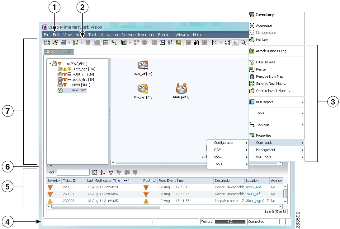
Prime Network allows you to perform basic operations on a selected network element. To perform the basic operation commands, you can launch it in a network element from the Prime Network Vision List or Map View. Figure 28-1 shows what happens when you right-click a network element. From here, you can choose Commands.


Note To view the basic operation commands in the Cisco Carrier Packet Transport (CPT) System, you must right-click the Cisco Carrier Packet Transport (CPT) System in the Prime Network Vision List or Map View and click Logical Inventory > CPT Context Container.


Note The basic operation commands in this chapter can be executed by all network elements that run on Cisco IOS software, Cisco IOS XR software, and Cisco NX OS software. You will not be able to execute these commands on network elements that have Cisco Catalyst OS software.


Figure 28-1 Basic Operation Commands

1

Menu Bar

5

Ticket Pane

2

Tool bar

6

Hide/display Ticket Pane

3

Device Right-click Menu

7

Navigation Pane

4

Status Bar


The basic operation commands that you can perform include:

Configuration Commands

Show Commands

Tools Commands

OAM Commands

Configuration Commands

The configuration commands allow you to configure the selected network element. The commands include:

Add Interface Configuration

Remove Interface Configuration

Update Interface Configuration

Add Loopback Interface

Add Port Description

Remove Port Description

Update Port Description

Change Port Status

Enable traps

Remove Access List

Remove Access List Entry

Remove Rate Limit

Write Memory

Disable Interface

Enable Interface

Assign Port To Vlan

DeAssign Port To Vlan

Add Host Name

Remove Host Name

Add DNS Server

Remove DNS Server

Add NTP Server

Remove NTP Server

Syslog Host Logging

Add Traps

Remove Traps

Add Radius Server

Remove Radius Server

Add Tacacs Server

Remove Tacacs Server

Add Tacacs+ Server

Remove Tacacs+ Server

Add SNMP Configuration

Remove SNMP Configuration

Update SNMP Configuration

Add Interface Configuration

Use the Add Interface Configuration command to add an interface configuration to the selected network element.


Step 1 In the Network Vision List or Map View, right-click the network element.

Step 2 Choose Physical Inventory.

Step 3 Choose the corresponding interface and right-click, choose Commands > Configuration > Add Interface Configuration.

Step 4 Enter the value for the following parameters.

.

Input Parameter
Description

IP Address Type

The IP address family- can be IPv4 or IPv6

IP Address

The IP address - can be IPv4 or IPv6

Mask

The subnet mask IP address.

Description

The description of the interface.


Step 5 To see the commands that will be applied on the device, click Preview.

Step 6 You can view the commands in the Result tab. You can go back and make any required changes to the input parameters.

Step 7 To schedule the command, click the Scheduling tab. For more details on scheduling, see Scheduling a Command.

Step 8 To run the commands, click Execute Now.

You can view errors in the Result tab, if there are any.

Step 9 To close the dialog box, click Close.


Remove Interface Configuration

Use the Remove Interface Configuration command to remove an interface configuration from the selected network element.


Step 1 In the Network Vision List or Map View, right-click the network element.

Step 2 Choose Logical Inventory > Routing Entities. Choose the corresponding interface and right-click.

Step 3 Choose Commands > Configuration > Remove Interface Configuration.

Step 4 To see the commands that will be applied on the device, click Preview.

Step 5 You can view the commands in the Result tab. You can go back and make any required changes to the input parameters.

Step 6 To schedule the command, click the Scheduling tab. For more details on scheduling, see Scheduling a Command.

Step 7 To run the commands, click Execute Now.

You can view errors in the Result tab, if there are any.

Step 8 To close the dialog box, click Close.


Update Interface Configuration

Use the Update Interface Configuration command to update an interface configuration on the selected network element.


Step 1 In the Network Vision List or Map View, right-click the network element.

Step 2 Choose Logical Inventory > Routing Entities. Choose the corresponding interface and right-click.

Step 3 Choose Commands > Configuration > Update Interface Configuration.

Step 4 Enter the value for the following parameter.

Input Parameter
Description

Description

The description of the interface.


Step 5 To see the commands that will be applied on the device, click Preview.

Step 6 You can view the commands in the Result tab. You can go back and make any required changes to the input parameters.

Step 7 To schedule the command, click the Scheduling tab. For more details on scheduling, see Scheduling a Command.

Step 8 To run the commands, click Execute Now.

You can view errors in the Result tab, if there are any.

Step 9 To close the dialog box, click Close.


Add Loopback Interface

Use the Add Loopback Interface command to add a loop back interface on the selected network element.


Step 1 In the Network Vision List or Map View, right-click the network element.

Step 2 Choose Commands > Configuration > Add Loopback Interface.

Step 3 Enter the value for the following parameter

.

Input Parameter
Description

IPAddress Type

The IP address family- can be IPv4 or IPv6

Address

The IP address - can be IPv4 or IPv6

Loopback ID

The loopback identifier of the IP address.

Mask

The subnet mask IP address - can be IPv4 or IPv6


Step 4 To see the commands that will be applied on the device, click Preview.

Step 5 You can view the commands in the Result tab. You can go back and make any required changes to the input parameters.

Step 6 To schedule the command, click the Scheduling tab. For more details on scheduling, see Scheduling a Command.

Step 7 To run the commands, click Execute Now.

You can view errors in the Result tab, if there are any.

Step 8 To close the dialog box, click Close.


Add Port Description

Use the Add port description command to add a port description on the selected network element.


Note This command is unavailable on the Cisco Carrier Packet Transport (CPT) System.


Step 1 In the Network Vision List or Map View, right-click the network element.

Step 2 Choose Physical Inventory.

Step 3 Choose the corresponding interface and right-click, choose Commands > Configuration > Add port description.

Step 4 Enter the value for the following parameter.

Input Parameter
Description

Description

The description of the port.


Step 5 To see the commands that will be applied on the device, click Preview.

Step 6 You can view the commands in the Result tab. You can go back and make any required changes to the input parameters.

Step 7 To schedule the command, click the Scheduling tab. For more details on scheduling, see Scheduling a Command.

Step 8 To run the commands, click Execute Now.

You can view errors in the Result tab, if there are any.

Step 9 To close the dialog box, click Close.


Remove Port Description

Use the Remove port description command to remove a port description on the selected network element.


Note This command is unavailable on the Cisco Carrier Packet Transport (CPT) System.


Step 1 In the Network Vision List or Map View, right-click the network element.

Step 2 Choose Physical Inventory.

Step 3 Choose the corresponding interface and right-click, choose Commands > Configuration > Remove port description.

Step 4 To see the commands that will be applied on the device, click Preview.

Step 5 You can view the commands in the Result tab. You can go back and make any required changes to the input parameters.

Step 6 To schedule the command, click the Scheduling tab. For more details on scheduling, see Scheduling a Command.

Step 7 To run the commands, click Execute Now.

You can view errors in the Result tab, if there are any.

Step 8 To close the dialog box, click Close.


Update Port Description

Use the Update port description command to update the port description on the selected network element.


Note This command is unavailable on the Cisco Carrier Packet Transport (CPT) System.


Step 1 In the Network Vision List or Map View, right-click the network element.

Step 2 Choose Physical Inventory.

Step 3 Choose the corresponding interface and right-click, choose Commands > Configuration > Update port description.

Step 4 Enter the value for the following parameter.

Input Parameter
Description

Description

The description of the port.


Step 5 To see the commands that will be applied on the device, click Preview.

Step 6 You can view the commands in the Result tab. You can go back and make any required changes to the input parameters.

Step 7 To schedule the command, click the Scheduling tab. For more details on scheduling, see Scheduling a Command.

Step 8 To run the commands, click Execute Now.

You can view errors in the Result tab, if there are any.

Step 9 To close the dialog box, click Close.


Change Port Status

Use the Change port status command to add a loop back interface on the selected network element.


Note This command is unavailable on the Cisco Carrier Packet Transport (CPT) System.


Step 1 In the Network Vision List or Map View, right-click the network element.

Step 2 Choose Physical Inventory.

Step 3 Choose the corresponding interface and right-click, choose Commands > Configuration > Change Port Status.

Step 4 Enter the value for the following parameter.

Input Parameter
Description

Status

The status of the port.


Step 5 To see the commands that will be applied on the device, click Preview.

Step 6 You can view the commands in the Result tab. You can go back and make any required changes to the input parameters.

Step 7 To schedule the command, click the Scheduling tab. For more details on scheduling, see Scheduling a Command.

Step 8 To run the commands, click Execute Now.

You can view errors in the Result tab, if there are any.

Step 9 To close the dialog box, click Close.


Enable traps

Use the Enable traps command to enable traps on the selected network element.


Step 1 In the Network Vision List or Map View, right-click the network element.

Step 2 Choose Commands > Configuration > System > SNMP > Enable traps.

Step 3 Enter the value for the following parameter

.

Input Parameter
Description

Community

The community name.

Host address

The host address.


Step 4 To see the commands that will be applied on the device, click Preview.

Step 5 You can view the commands in the Result tab. You can go back and make any required changes to the input parameters.

Step 6 To schedule the command, click the Scheduling tab. For more details on scheduling, see Scheduling a Command.

Step 7 To run the commands, click Execute Now.

You can view errors in the Result tab, if there are any.

Step 8 To close the dialog box, click Close.


Remove Access List

Use the Remove access list command to remove the access list on the selected network element.


Note You can not execute this command on network elements that run on Cisco IOS XR software.


Step 1 In the Network Vision List or Map View, right-click the network element.

Step 2 Choose Commands > Configuration > System > Remove access list.

Step 3 To see the commands that will be applied on the device, click Preview.

Step 4 You can view the commands in the Result tab. You can go back and make any required changes to the input parameters.

Step 5 To schedule the command, click the Scheduling tab. For more details on scheduling, see Scheduling a Command.

Step 6 To run the commands, click Execute Now.

You can view errors in the Result tab, if there are any.

Step 7 To close the dialog box, click Close.


Remove Access List Entry

Use the Remove access list entry command to remve access list entry on the selected network element.


Note You can not execute this command on network elements that run on Cisco IOS XR software.


Step 1 In the Network Vision List or Map View, right-click the network element.

Step 2 Choose Commands > Configuration > System > Remove access list entry.

Step 3 To see the commands that will be applied on the device, click Preview.

Step 4 You can view the commands in the Result tab. You can go back and make any required changes to the input parameters.

Step 5 To schedule the command, click the Scheduling tab. For more details on scheduling, see Scheduling a Command.

Step 6 To run the commands, click Execute Now.

You can view errors in the Result tab, if there are any.

Step 7 To close the dialog box, click Close.


Remove Rate Limit

Use the Remove rate limit command to remove the rate limit on the selected network element.


Note You can not execute this command on network elements that run on Cisco IOS XR software.


Step 1 In the Network Vision List or Map View, right-click the network element.

Step 2 Choose Commands > Configuration > System > Remove rate limit.

Step 3 To see the commands that will be applied on the device, click Preview.

Step 4 You can view the commands in the Result tab. You can go back and make any required changes to the input parameters.

Step 5 To schedule the command, click the Scheduling tab. For more details on scheduling, see Scheduling a Command.

Step 6 To run the commands, click Execute Now.

You can view errors in the Result tab, if there are any.

Step 7 To close the dialog box, click Close.


Write Memory

Use the Write memory command to write memory on the selected network element.


Note You can not execute this command on network elements that run on Cisco IOS XR software.


Step 1 In the Network Vision List or Map View, right-click the network element.

Step 2 Choose Commands > Configuration > Write memory.

Step 3 To see the commands that will be applied on the device, click Preview.

Step 4 You can view the commands in the Result tab. You can go back and make any required changes to the input parameters.

Step 5 To schedule the command, click the Scheduling tab. For more details on scheduling, see Scheduling a Command.

Step 6 To run the commands, click Execute Now.

You can view errors in the Result tab, if there are any.

Step 7 To close the dialog box, click Close.


Disable Interface

Use the Disable Interface command to disable the interface on the selected network element.


Step 1 In the Network Vision List or Map View, right-click the network element.

Step 2 Choose Logical Inventory > Routing Entities. Choose the corresponding interface and right-click.

Step 3 Choose Commands > Configuration > Disable Interface.

Step 4 To see the commands that will be applied on the device, click Preview.

Step 5 You can view the commands in the Result tab. You can go back and make any required changes to the input parameters.

Step 6 To schedule the command, click the Scheduling tab. For more details on scheduling, see Scheduling a Command.

Step 7 To run the commands, click Execute Now.

You can view errors in the Result tab, if there are any.

Step 8 To close the dialog box, click Close.


Enable Interface

Use the Enable Interface command to enable the interface on the selected network element.


Step 1 In the Network Vision List or Map View, right-click the network element.

Step 2 Choose Logical Inventory > Routing Entities. Choose the corresponding interface and right-click.

Step 3 Choose Commands > Configuration > Enable Interface.

Step 4 To see the commands that will be applied on the device, click Preview.

Step 5 You can view the commands in the Result tab. You can go back and make any required changes to the input parameters.

Step 6 To schedule the command, click the Scheduling tab. For more details on scheduling, see Scheduling a Command.

Step 7 To run the commands, click Execute Now.

You can view errors in the Result tab, if there are any.

Step 8 To close the dialog box, click Close.


Assign Port To Vlan

Use the Assign Port To Vlan command to assign a port to VLAN on the selected network element.


Step 1 In the Network Vision List or Map View, right-click the network element.

Step 2 Choose Logical Inventory > Routing Entities. Choose the corresponding interface and right-click.

Step 3 Choose Commands > Configuration > Assign Port To Vlan.

Step 4 Enter the folowing parameter.

\

Input Parameter
Description

VLAN ID

The VLAN identifier. Value should be with in the range 1 to 4094.


Step 5 To see the commands that will be applied on the device, click Preview.

Step 6 You can view the commands in the Result tab. You can go back and make any required changes to the input parameters.

Step 7 To schedule the command, click the Scheduling tab. For more details on scheduling, see Scheduling a Command.

Step 8 To run the commands, click Execute Now.

You can view errors in the Result tab, if there are any.

Step 9 To close the dialog box, click Close.


DeAssign Port To Vlan

Use the DeAssign Port To Vlan command to de-assign a port to VLAN on the selected network element.


Step 1 In the Network Vision List or Map View, right-click the network element.

Step 2 Choose Logical Inventory > Routing Entities. Choose the corresponding interface and right-click.

Step 3 Choose Commands > Configuration > DeAssign Port To Vlan.

Step 4 To see the commands that will be applied on the device, click Preview.

Step 5 You can view the commands in the Result tab. You can go back and make any required changes to the input parameters.

Step 6 To schedule the command, click the Scheduling tab. For more details on scheduling, see Scheduling a Command.

Step 7 To run the commands, click Execute Now.

You can view errors in the Result tab, if there are any.

Step 8 To close the dialog box, click Close.


Add Host Name

Use the Add Host Name command to add a host name on the selected network element.


Step 1 In the Network Vision List or Map View, right-click the network element.

Step 2 Choose Commands > Configuration > System > Add Host Name.

Step 3 Enter the value for the following parameter.

Input Parameter
Description

Host name

The name of the host.


Step 4 To see the commands that will be applied on the device, click Preview.

Step 5 You can view the commands in the Result tab. You can go back and make any required changes to the input parameters.

Step 6 To schedule the command, click the Scheduling tab. For more details on scheduling, see Scheduling a Command.

Step 7 To run the commands, click Execute Now.

You can view errors in the Result tab, if there are any.

Step 8 To close the dialog box, click Close.


Remove Host Name

Use the Remove Host Name command to remove a host name on the selected network element.


Step 1 In the Network Vision List or Map View, right-click the network element.

Step 2 Choose Commands > Configuration > System > Remove Host Name.

Step 3 To see the commands that will be applied on the device, click Preview.

Step 4 You can view the commands in the Result tab. You can go back and make any required changes to the input parameters.

Step 5 To schedule the command, click the Scheduling tab. For more details on scheduling, see Scheduling a Command.

Step 6 To run the commands, click Execute Now.

You can view errors in the Result tab, if there are any.

Step 7 To close the dialog box, click Close.


Add DNS Server

Use the Add DNS Server command to add a DNS server to the selected network element.


Step 1 In the Network Vision List or Map View, right-click the network element.

Step 2 Choose Commands > Configuration > System > DNS > Add DNS Server.

Step 3 Enter the values for the following parameters

Input Parameter
Description

Domain Name

The name of the domain.

Domain List

The name of the domain list.

Domain Name Server Address 1 ([A.B.C.D])

The domain name server address 1.


Step 4 To see the commands that will be applied on the device, click Preview.

Step 5 You can view the commands in the Result tab. You can go back and make any required changes to the input parameters.

Step 6 To schedule the command, click the Scheduling tab. For more details on scheduling, see Scheduling a Command.

Step 7 To run the commands, click Execute Now.

You can view errors in the Result tab, if there are any.

Step 8 To close the dialog box, click Close.


Remove DNS Server

Use the Remove DNS Server command to add a DNS server from the selected network element.


Step 1 In the Network Vision List or Map View, right-click the network element.

Step 2 Choose Commands > Configuration > System > DNS > Remove DNS Server.

Step 3 Enter the values for the following parameters

Input Parameter
Description

Domain Name

The name of the domain

Domain List

The name of the domain list

Domain Name Server Address 1 ([A.B.C.D])

The domain name server address 1.


Step 4 To see the commands that will be applied on the device, click Preview.

Step 5 You can view the commands in the Result tab. You can go back and make any required changes to the input parameters.

Step 6 To schedule the command, click the Scheduling tab. For more details on scheduling, see Scheduling a Command.

Step 7 To run the commands, click Execute Now.

You can view errors in the Result tab, if there are any.

Step 8 To close the dialog box, click Close.


Add NTP Server

Use the Add NTP Server command to add a NTP server from the selected network element.


Step 1 In the Network Vision List or Map View, right-click the network element.

Step 2 Choose Commands > Configuration > System > NTP > Add NTP Server.

Step 3 Enter the values for the following parameters

Input Parameter
Description

IPAddress Type

The address family- IPV4 or IPV6 values.

NTP Server Address

The NTP server IP address.

Version Number

The version number.

Key Id

The key identifier. The range should be from 0 to 4294967295.

Interface Name

The name of the interface.


Step 4 To see the commands that will be applied on the device, click Preview.

Step 5 You can view the commands in the Result tab. You can go back and make any required changes to the input parameters.

Step 6 To schedule the command, click the Scheduling tab. For more details on scheduling, see Scheduling a Command.

Step 7 To run the commands, click Execute Now.

You can view errors in the Result tab, if there are any.

Step 8 To close the dialog box, click Close.


Remove NTP Server

Use the Remove NTP Server command to remove a NTP server from the selected network element.


Step 1 In the Network Vision List or Map View, right-click the network element.

Step 2 Choose Commands > Configuration > System > NTP > Remove NTP Server.

Step 3 Enter the values for the following parameter.

NTP Server Address, The NTP server IP address.

Step 4 To see the commands that will be applied on the device, click Preview.

Step 5 You can view the commands in the Result tab. You can go back and make any required changes to the input parameters.

Step 6 To schedule the command, click the Scheduling tab. For more details on scheduling, see Scheduling a Command.

Step 7 To run the commands, click Execute Now.

You can view errors in the Result tab, if there are any.

Step 8 To close the dialog box, click Close.


Syslog Host Logging

Use the Syslog Host Logging command to view the syslogs of host logging on the selected network element.


Step 1 In the Network Vision List or Map View, right-click the network element.

Step 2 Choose Commands > Configuration > System > Syslog Host Logging.

Step 3 Enter the values for the following parameters

Input Parameter
Description

Host Type

The host type- IPV4 or IPV6 host.

Logging Host

The IP address of the logging host.

Logging Buffer Size

Logging buffer size. Value should be in the range from 4096 to 2147483647.

Logging Buffered

Logging Buffered

Logging Facility

Logging Facility

Logging Severity Level

Logging Severity Level

Logging History

Logging History


Step 4 To see the commands that will be applied on the device, click Preview.

Step 5 You can view the commands in the Result tab. You can go back and make any required changes to the input parameters.

Step 6 To schedule the command, click the Scheduling tab. For more details on scheduling, see Scheduling a Command.

Step 7 To run the commands, click Execute Now.

You can view errors in the Result tab, if there are any.

Step 8 To close the dialog box, click Close.


Add Traps

Use the Add Traps command to add traps on the selected network element.


Step 1 In the Network Vision List or Map View, right-click the network element.

Step 2 Choose Commands > Configuration > System > Snmp > Add Traps.

Step 3 Enter the values for the following parameters

Input Parameter
Description

Trap 1

Trap list 1

Trap 2

Trap list 2

Trap 3

Trap list 3

Trap 4

Trap list 4

Trap 5

Trap list 5

Trap 6

Trap list 6

Trap 7

Trap list 7


Step 4 To see the commands that will be applied on the device, click Preview.

Step 5 You can view the commands in the Result tab. You can go back and make any required changes to the input parameters.

Step 6 To schedule the command, click the Scheduling tab. For more details on scheduling, see Scheduling a Command.

Step 7 To run the commands, click Execute Now.

You can view errors in the Result tab, if there are any.

Step 8 To close the dialog box, click Close.


Remove Traps

Use the Remove Traps command to remove traps on the selected network element.


Step 1 In the Network Vision List or Map View, right-click the network element.

Step 2 Choose Commands > Configuration > System > Snmp > Remove Traps.

Step 3 Enter the values for the following parameters.

Input Parameter
Description

Trap 1

Trap list 1

Trap 2

Trap list 2

Trap 3

Trap list 3

Trap 4

Trap list 4

Trap 5

Trap list 5

Trap 6

Trap list 6

Trap 7

Trap list 7


Step 4 To see the commands that will be applied on the device, click Preview.

Step 5 You can view the commands in the Result tab. You can go back and make any required changes to the input parameters.

Step 6 To schedule the command, click the Scheduling tab. For more details on scheduling, see Scheduling a Command.

Step 7 To run the commands, click Execute Now.

You can view errors in the Result tab, if there are any.

Step 8 To close the dialog box, click Close.


Add Radius Server

Use the Add Radius Server command to add a radius server on the selected network element.


Step 1 In the Network Vision List or Map View, right-click the network element.

Step 2 Choose Commands > Configuration > System > RADIUS > Add Radius Server.

Step 3 Enter the values for the following parameters

Input Parameter
Description

Radius Server Host Address

The radius server host IP address

Authentication port value

The authentication port. Value should be in the range 0 to 65535.

key-value

The key-value of th radius server??

Authentication List Name

The authentication list name.

Group Name

The name of the group.


Step 4 To see the commands that will be applied on the device, click Preview.

Step 5 You can view the commands in the Result tab. You can go back and make any required changes to the input parameters.

Step 6 To schedule the command, click the Scheduling tab. For more details on scheduling, see Scheduling a Command.

Step 7 To run the commands, click Execute Now.

You can view errors in the Result tab, if there are any.

Step 8 To close the dialog box, click Close.


Remove Radius Server

Use the Remove Radius Server command to remove a radius server on the selected network element.


Step 1 In the Network Vision List or Map View, right-click the network element.

Step 2 Choose Commands > Configuration > System > RADIUS > Remove Radius Server.

Step 3 Enter the values for the following parameters

Input Parameter
Description

Radius Server Host Address

The radius server host IP address

Authentication List Name

The authentication list name.


Step 4 To see the commands that will be applied on the device, click Preview.

Step 5 You can view the commands in the Result tab. You can go back and make any required changes to the input parameters.

Step 6 To schedule the command, click the Scheduling tab. For more details on scheduling, see Scheduling a Command.

Step 7 To run the commands, click Execute Now.

You can view errors in the Result tab, if there are any.

Step 8 To close the dialog box, click Close.


Add Tacacs Server

Use the Add Tacacs Server command to add a TACAS server on the selected network element.


Step 1 In the Network Vision List or Map View, right-click the network element.

Step 2 Choose Commands > Configuration > System > TACACS > Add Tacacs Server.

Step 3 Enter the values for the following parameters

Input Parameter
Description

Tacacs Server Host Address

The TACAS Server Host IP Address.

Retransmit Value

The retransmit value. Values should be in the range 0 to 100.

Timeout Value

The timeout value. Value should be in the range 1 to 1000.


Step 4 To see the commands that will be applied on the device, click Preview.

Step 5 You can view the commands in the Result tab. You can go back and make any required changes to the input parameters.

Step 6 To schedule the command, click the Scheduling tab. For more details on scheduling, see Scheduling a Command.

Step 7 To run the commands, click Execute Now.

You can view errors in the Result tab, if there are any.

Step 8 To close the dialog box, click Close.


Remove Tacacs Server

Use the Remove Tacacs Server command to remove a TACAS server on the selected network element.


Step 1 In the Network Vision List or Map View, right-click the network element.

Step 2 Choose Commands > Configuration > System > TACACS > Remove Tacacs Server.

Step 3 Enter the values for the following parameters

Input Parameter
Description

Tacacs Server Host Address

The TACAS Server Host IP Address.


Step 4 To see the commands that will be applied on the device, click Preview.

Step 5 You can view the commands in the Result tab. You can go back and make any required changes to the input parameters.

Step 6 To schedule the command, click the Scheduling tab. For more details on scheduling, see Scheduling a Command.

Step 7 To run the commands, click Execute Now.

You can view errors in the Result tab, if there are any.

Step 8 To close the dialog box, click Close.


Add Tacacs+ Server

Use the Add Tacacs Server command to add a TACAS+ server on the selected network element.


Step 1 In the Network Vision List or Map View, right-click the network element.

Step 2 Choose Commands > Configuration > System > TACACS+ > Add Tacacs+ Server.

Step 3 Enter the values for the following parameters

Input Parameter
Description

Tacacs+ Server Host Address

The TACACS+ server host IP address.

key-value

The key-value.

Authentication List Name

The authentication list name.

Group Name

The name of the group.


Step 4 To see the commands that will be applied on the device, click Preview.

Step 5 You can view the commands in the Result tab. You can go back and make any required changes to the input parameters.

Step 6 To schedule the command, click the Scheduling tab. For more details on scheduling, see Scheduling a Command.

Step 7 To run the commands, click Execute Now.

You can view errors in the Result tab, if there are any.

Step 8 To close the dialog box, click Close.


Remove Tacacs+ Server

Use the Add Tacacs Server command to remove a TACAS+ server on the selected network element.


Step 1 In the Network Vision List or Map View, right-click the network element.

Step 2 Choose Commands > Configuration > System > TACACS+ > Remove Tacacs+ Server.

Step 3 Enter the values for the following parameters.

Input Parameter
Description

Tacacs+ Server Host Address

The TACACS+ server host IP address.

Authentication List Name

The authentication list name.


Step 4 To see the commands that will be applied on the device, click Preview.

Step 5 You can view the commands in the Result tab. You can go back and make any required changes to the input parameters.

Step 6 To schedule the command, click the Scheduling tab. For more details on scheduling, see Scheduling a Command.

Step 7 To run the commands, click Execute Now.

You can view errors in the Result tab, if there are any.

Step 8 To close the dialog box, click Close.


Add SNMP Configuration

Use the Add Snmp Configuration command to add an SNMP configuration on the selected network element.


Step 1 In the Network Vision List or Map View, right-click the network element.

Step 2 Choose Commands > Configuration > System > Snmp > Add Snmp Configuration.

Step 3 Enter the values for the following parameters.

Input Parameter
Description

Host address

The host address.

Community String

The community string.

Community Access Type

Community Access Type

Trap community Type

The trap community type.

Snmp Engine ID

The SNMP engine identifier.

Snmp Server View Name

The SNMP server view name.

MIB View Family Name

The MIB view family name.

MIB family Included/Excluded from the view

The MIB family Included/Excluded from the view.

Snmp Server Group Name

The SNMP server group name.

SNMPv3 Group Security Model

The SNMPv3 group security model.

Group Read View Name

The group read view name.

Group Write View Name

The group write view nam.e

Group Notify View Name

The group notify view name.

Snmp Server User Name

The SNMP server user name.

SNMPv3 User Security Model

The SNMPv3 user security model.

Authentication Password

The authentication password.


Step 4 To see the commands that will be applied on the device, click Preview.

Step 5 You can view the commands in the Result tab. You can go back and make any required changes to the input parameters.

Step 6 To schedule the command, click the Scheduling tab. For more details on scheduling, see Scheduling a Command.

Step 7 To run the commands, click Execute Now.

You can view errors in the Result tab, if there are any.

Step 8 To close the dialog box, click Close.


Remove SNMP Configuration

Use the Remove Snmp Configuration command to remove an SNMP configuration on the selected network element.


Step 1 In the Network Vision List or Map View, right-click the network element.

Step 2 Choose Commands > Configuration > System > Snmp > Remove Snmp Configuration.

Step 3 Enter the values for the following parameters

Input Parameter
Description

Host address

The host address.

Community String

The community string.

Trap community Type

The trap community type.

Snmp Server View Name

The SNMP server view name.

Snmp Server Group Name

The SNMP server group name.

SNMPv3 Group Security Model

The SNMPv3 group security model.

Snmp Server User Name

The SNMP server user name.


.

Step 4 To see the commands that will be applied on the device, click Preview.

Step 5 You can view the commands in the Result tab. You can go back and make any required changes to the input parameters.

Step 6 To schedule the command, click the Scheduling tab. For more details on scheduling, see Scheduling a Command.

Step 7 To run the commands, click Execute Now.

You can view errors in the Result tab, if there are any.

Step 8 To close the dialog box, click Close.


Update SNMP Configuration

Use the Update Snmp Configuration command to add an SNMP configuration on the selected network element.


Step 1 In the Network Vision List or Map View, right-click the network element.

Step 2 Choose Commands > Configuration > System > Snmp > Update Snmp Configuration.

Step 3 Enter the values for the following parameters.

Input Parameter
Description

Host address

The host address.

Community String

The community string.

Community Access Type

Community Access Type

Trap community Type

The trap community type.

Snmp Server View Name

The SNMP server view name.

MIB View Family Name

The MIB view family name.

MIB family Included/Excluded from the view

The MIB family Included/Excluded from the view.

Snmp Server Group Name

The SNMP server group name.

SNMPv3 Group Security Model

The SNMPv3 group security model.

Group Read View Name

The group read view name.

Group Write View Name

The group write view name.

Group Notify View Name

The group notify view name.

Snmp Server User Name

The SNMP server user name.

SNMPv3 User Security Model

The SNMPv3 user security model.

Authentication Password

The authentication password.


Step 4 To see the commands that will be applied on the device, click Preview.

Step 5 You can view the commands in the Result tab. You can go back and make any required changes to the input parameters.

Step 6 To schedule the command, click the Scheduling tab. For more details on scheduling, see Scheduling a Command.

Step 7 To run the commands, click Execute Now.

You can view errors in the Result tab, if there are any.

Step 8 To close the dialog box, click Close.


Show Commands

The show commands allow you to show the details of the selected network element. The commands include:

Interface Brief

IP Route

VRF IP Route

Running Config

Running Config from File

Startup Config

Users (Telnet Sessions)

Interface Brief

Use the Interface Brief command to provide more brief information on the selected network element.


Step 1 In the Network Vision List or Map View, right-click the network element.

Step 2 Choose Commands > Show > IP > Interface Brief.

Step 3 To see the commands that will be applied on the device, click Preview.

Step 4 You can view the commands in the Result tab. You can go back and make any required changes to the input parameters.

Step 5 To schedule the command, click the Scheduling tab. For more details on scheduling, see Scheduling a Command.

Step 6 To run the commands, click Execute Now.

You can view errors in the Result tab, if there are any.

Step 7 To close the dialog box, click Close.


IP Route

Use the IP route command to provide more brief information of the IP route of the selected network element.


Step 1 In the Network Vision List or Map View, right-click the network element.

Step 2 Choose Commands > Show > IP route.

Step 3 To see the commands that will be applied on the device, click Preview.

Step 4 You can view the commands in the Result tab. You can go back and make any required changes to the input parameters.

Step 5 To schedule the command, click the Scheduling tab. For more details on scheduling, see Scheduling a Command.

Step 6 To run the commands, click Execute Now.

You can view errors in the Result tab, if there are any.

Step 7 To close the dialog box, click Close.


VRF IP Route

Use the VRF IP route command to provide information on the VRF IP route of the selected network element.


Step 1 In the Network Vision List or Map View, right-click the network element.

Step 2 Choose Commands > Show > VRF IP route.

Step 3 To see the commands that will be applied on the device, click Preview.

Step 4 You can view the commands in the Result tab. You can go back and make any required changes to the input parameters.

Step 5 To schedule the command, click the Scheduling tab. For more details on scheduling, see Scheduling a Command.

Step 6 To run the commands, click Execute Now.

You can view errors in the Result tab, if there are any.

Step 7 To close the dialog box, click Close.


Running Config

Use the Running Config command to view the running configuration of the selected network element.


Step 1 In the Network Vision List or Map View, right-click the network element.

Step 2 Choose Commands > Show > Running Config.

Step 3 To see the commands that will be applied on the device, click Preview.

Step 4 You can view the commands in the Result tab. You can go back and make any required changes to the input parameters.

Step 5 To schedule the command, click the Scheduling tab. For more details on scheduling, see Scheduling a Command.

Step 6 To run the commands, click Execute Now.

You can view errors in the Result tab, if there are any.

Step 7 To close the dialog box, click Close.


Running Config from File

Use the Running Config from file command to view the running configuration of the selected network element from the file.


Step 1 In the Network Vision List or Map View, right-click the network element.

Step 2 Choose Commands > Show > Running Config from file.

Step 3 To see the commands that will be applied on the device, click Preview.

Step 4 You can view the commands in the Result tab. You can go back and make any required changes to the input parameters.

Step 5 To schedule the command, click the Scheduling tab. For more details on scheduling, see Scheduling a Command.

Step 6 To run the commands, click Execute Now.

You can view errors in the Result tab, if there are any.

Step 7 To close the dialog box, click Close.


Startup Config

Use the Startup Config command to view the start-up configuration of the selected network element.


Step 1 In the Network Vision List or Map View, right-click the network element.

Step 2 Choose Commands > Show > Startup Config.

Step 3 To see the commands that will be applied on the device, click Preview.

Step 4 You can view the commands in the Result tab. You can go back and make any required changes to the input parameters.

Step 5 To schedule the command, click the Scheduling tab. For more details on scheduling, see Scheduling a Command.

Step 6 To run the commands, click Execute Now.

You can view errors in the Result tab, if there are any.

Step 7 To close the dialog box, click Close.


Users (Telnet Sessions)

Use the Users (Telnet Sessions) command to view the details of the telnet sessions of the selected network element.


Step 1 In the Network Vision List or Map View, right-click the network element.

Step 2 Choose Commands > Show > Users (Telnet Sessions).

Step 3 To see the commands that will be applied on the device, click Preview.

Step 4 You can view the commands in the Result tab. You can go back and make any required changes to the input parameters.

Step 5 To schedule the command, click the Scheduling tab. For more details on scheduling, see Scheduling a Command.

Step 6 To run the commands, click Execute Now.

You can view errors in the Result tab, if there are any.

Step 7 To close the dialog box, click Close.


Tools Commands

The tools commands allow you to transfer files from the selected network element. The commands include:

From FTP

From TFTP

To FTP

To TFTP


Note The tools commands are unavailable on the Cisco Carrier Packet Transport (CPT) System.


From FTP

Use the From FTP command to perform FTP on the selected network element.


Step 1 In the Network Vision List or Map View, right-click the network element.

Step 2 Choose Commands > Tools > File copy > From FTP.

Step 3 Enter the value for the following parameter.

Input Parameter
Description

Source File

The configuration source file type.

Dest file

The destination configuration file type- running config or start-up config.

Password

The FTP password.

Source IP

The source IP address

Source file

The configuration source file type.

User

The FTP user name


Step 4 To see the commands that will be applied on the device, click Preview.

Step 5 You can view the commands in the Result tab. You can go back and make any required changes to the input parameters.

Step 6 To schedule the command, click the Scheduling tab. For more details on scheduling, see Scheduling a Command.

Step 7 To run the commands, click Execute Now.

You can view errors in the Result tab, if there are any.

Step 8 To close the dialog box, click Close.


From TFTP

Use the From TFTP command to perform TFTP on the selected network element.


Step 1 In the Network Vision List or Map View, right-click the network element.

Step 2 Choose Commands > Tools > File copy > From TFTP.

Step 3 Enter the value for the following parameter.

Input Parameter
Description

Dest file

The destination configuration file type.

Source IP

The source IP address.

Source file

The configuration source file type.


Step 4 To see the commands that will be applied on the device, click Preview.

Step 5 You can view the commands in the Result tab. You can go back and make any required changes to the input parameters.

Step 6 To schedule the command, click the Scheduling tab. For more details on scheduling, see Scheduling a Command.

Step 7 To run the commands, click Execute Now.

You can view errors in the Result tab, if there are any.

Step 8 To close the dialog box, click Close.


To FTP

Use the To FTP command to perform FTP on the selected network element.


Step 1 In the Network Vision List or Map View, right-click the network element.

Step 2 Choose Commands > Tools > File copy > To FTP.

Step 3 Enter the value for the following parameter

Input Parameter
Description

Destination IP

The destination IP address.

Destination file

The destination file.

Password

The FTP password.

Source file

The source configuration file type.

User

The FTP user name.


Step 4 To see the commands that will be applied on the device, click Preview.

Step 5 You can view the commands in the Result tab. You can go back and make any required changes to the input parameters.

Step 6 To schedule the command, click the Scheduling tab. For more details on scheduling, see Scheduling a Command.

Step 7 To run the commands, click Execute Now.

You can view errors in the Result tab, if there are any.

Step 8 To close the dialog box, click Close.


To TFTP

Use the To TFTP command to perform TFTP on the selected network element.


Step 1 In the Network Vision List or Map View, right-click the network element.

Step 2 Choose Commands > Tools > File copy > To FTP.

Step 3 Enter the value for the following parameter.

Input Parameter
Description

Destination IP

The destination IP address

Destination file

The destination file

Source file

The source configuration file type


Step 4 To see the commands that will be applied on the device, click Preview.

Step 5 You can view the commands in the Result tab. You can go back and make any required changes to the input parameters.

Step 6 To schedule the command, click the Scheduling tab. For more details on scheduling, see Scheduling a Command.

Step 7 To run the commands, click Execute Now.

You can view errors in the Result tab, if there are any.

Step 8 To close the dialog box, click Close.


OAM Commands

TheOAM commands allow you to perform operations, administration, and maintanence operations on the selected network element. The commands include:

Destination From Device

Ping VRF

Trace Route From Device

Trace Route VRF

Destination From Device

Use the Destination From Device command to view the destination from device on the selected network element.


Step 1 In the Network Vision List or Map View, right-click the network element.

Step 2 Choose Commands > OAM > Ping > Destination From Device.

Step 3 Enter the value for the following parameter.

Input Parameter
Description

Destination address

The destination address.


Step 4 To see the commands that will be applied on the device, click Preview.

Step 5 You can view the commands in the Result tab. You can go back and make any required changes to the input parameters.

Step 6 To schedule the command, click the Scheduling tab. For more details on scheduling, see Scheduling a Command.

Step 7 To run the commands, click Execute Now.

You can view errors in the Result tab, if there are any.

Step 8 To close the dialog box, click Close.


Ping VRF

Use the Ping VRF command to perform ping VRF on the selected network element.


Step 1 In the Network Vision List or Map View, right-click the network element.

Step 2 Choose Commands > OAM > Ping VRF.

Step 3 Enter the value for the following parameter

.

Input Parameter
Description

Destination address

The destination address.


Step 4 To see the commands that will be applied on the device, click Preview.

Step 5 You can view the commands in the Result tab. You can go back and make any required changes to the input parameters.

Step 6 To schedule the command, click the Scheduling tab. For more details on scheduling, see Scheduling a Command.

Step 7 To run the commands, click Execute Now.

You can view errors in the Result tab, if there are any.

Step 8 To close the dialog box, click Close.


Trace Route From Device

Use the Trace Route From Device command to view the trace route from the selected network element.


Step 1 In the Network Vision List or Map View, right-click the network element.

Step 2 Choose Commands > OAM > Trace Route From Device.

Step 3 Enter the value for the following parameter

.

Input Parameter
Description

Destination address

The destination address.


Step 4 To see the commands that will be applied on the device, click Preview.

Step 5 You can view the commands in the Result tab. You can go back and make any required changes to the input parameters.

Step 6 To schedule the command, click the Scheduling tab. For more details on scheduling, see Scheduling a Command.

Step 7 To run the commands, click Execute Now.

You can view errors in the Result tab, if there are any.

Step 8 To close the dialog box, click Close.


Trace Route VRF

Use the Trace Route VRF command to view the trace route VRF from the selected network element.


Step 1 In the Network Vision List or Map View, right-click the network element.

Step 2 Choose Commands > OAM > Trace Route VRF.

Step 3 Enter the value for the following parameter.

Input Parameter
Description

Destination address

The destination address.


Step 4 To see the commands that will be applied on the device, click Preview.

Step 5 You can view the commands in the Result tab. You can go back and make any required changes to the input parameters.

Step 6 To schedule the command, click the Scheduling tab. For more details on scheduling, see Scheduling a Command.

Step 7 To run the commands, click Execute Now.

You can view errors in the Result tab, if there are any.

Step 8 To close the dialog box, click Close.


Scheduling a Command

You can specify when you want to execute a command using the Scheduling tab of the commands window.

To schedule a command, you must:


Step 1 In the Network Vision List or Map View, right-click the network element.

Step 2 Choose Commands and then select the desired command.

Step 3 Click the Scheduling tab.

Step 4 Choose Execute Now to execute the command at that instance.

Step 5 Choose Schedule Job to schedule the command to execute later.

a. Click Once to specify the command to execute only once. You must specify the date and the time you want the command to execute.

b. Click Recurring to specify that you want the command to be executed in a recurring manner. You must specify the from and to date and time. You can execute the command:

Every specific time. For example every twenty minutes.

Daily- You can select Daily if you want the selected command to be executed every day.

Weekly- You can select which day of the week you want to execute the command.

Monthly- You can select which day of the month you want to execute the comand.

Step 6 Enter the values for the comment.

Step 7 To preview the executed command, click Preview.

Step 8 To execute the command as specified in the command window, click Execute Now.

Step 9 To close the window, click Close.