-
Cisco Prime Cable Provisioning User Guide, 5.0
-
Preface
- Getting Started
-
Configuring Prime Cable Provisioning
-
Configuring Prime Cable Provisioning Components
-
Configuring Technologies in Prime Cable Provisioning
-
Configuring Secure Communication
-
Configuring IPv6
-
Configuring the Syslog Utility to Receive Prime Cable Provisioning Alerts
-
Configuring Prime Cable Provisioning Using the User Interface
-
Configuring Groups Using the Admin UI
-
Configuring RBAC Using the Admin UI
-
- Provisioning the Management System
- Monitoring Cisco Prime Cable Provisioning
- Troubleshooting Cisco Prime Cable Provisioning
- Appendices
-
Glossary
-
Index
-
 Feedback
Table Of Contents
Configuring Technologies in Prime Cable Provisioning
Extended CMTS MIC Shared Secret
PacketCable TLV 38 and MIB Support
Configuring PacketCable Secure
Cisco Prime Cable Provisioning PacketCable Secure Provisioning Flow
Configuring SRV Records in the Network Registrar DNS Server
Adding a Dial Plan for PacketCable 2.0 Groovy
Configuring SNMPv3 Cloning on RDU and DPE for Secure Communication with PacketCable MTAs
Creating the Key Material and Generating the Key
Configuring Euro-PacketCable MIBs
Differences between DPoE and DOCSIS Provisioning
Configuring Prime Network Registrar
Configuring CableHome WAN-Data
Configuring Technologies in Prime Cable Provisioning
This chapter describes the tasks that you must perform when configuring Prime Cable Provisioning to support specific technologies:
Configuring DOCSIS
This section describes the tasks that you must perform when configuring Prime Cable Provisioning to support the DOCSIS technologies.
Note
See DOCSIS Option Support, for information on DOCSIS options supported by this Prime Cable Provisioning release.
DOCSIS Workflow
Prime Cable Provisioning supports these versions of the DOCSIS specifications: 1.0, 1.1, 2.0, and 3.0.
To successfully configure Prime Cable Provisioning for DOCSIS operations, you must configure the components as described in Chapter 6, "Configuring Prime Cable Provisioning Components", in addition to those described in this section.
Table 7-1 identifies the workflow to follow when configuring Prime Cable Provisioning to support DOCSIS.
Table 7-1 DOCSIS Workflow
Step 1
Configure the RDU
a.
b.
c.
Step 2
Configure the DPE
a.
The service tftp 1..1 ipv4 | ipv6 enabled true command described in the Cisco Prime Cable Provisioning 5.0 DPE CLI Reference Guide.
b.
The service tod 1..1 ipv4 | ipv6 enabled true command described in the Cisco Prime Cable Provisioning 5.0 DPE CLI Reference Guide.
Step 3
Configure Cisco Prime Network Registrar
Configure client classes/selection tags to match those added for the provisioned DOCSIS modem DHCP Criteria.
DOCSIS Shared Secret
Prime Cable Provisioning lets you define a different DOCSIS shared secret (DSS) for each cable modem termination system (CMTS). In this way, a compromised shared secret affects only a limited number of CMTS, instead of every CMTS in the deployment.
Although the DSS can be set for each DPE, you should set it on a provisioning-group basis. Also, ensure that it matches what has been configured for the CMTS in that provisioning group.
Caution
You can enter the shared secret as a clear text string or as an IOS-encrypted string. When entered in clear text, the DSS is encrypted to suit IOS version 12.2BC.
You can also set the DSS from the RDU using the administrator user interface or the API. In this case, the DSS is entered, stored at the RDU, and passed to all DPEs in clear text. Consequently, before a DSS entered this way is stored on the DPE, it is encrypted.
If you set the DSS directly at the DPE using the dpe docsis shared-secret command from the CLI, this DSS takes precedence over the one set from the RDU.
Resetting the DOCSIS Shared Secret
You can reset the DSS if the security of the DSS is compromised or to simply change the shared secret for administrative purposes.
To reset the DSS, run the show running-config command from the CMTS CLI, then copy and paste the DOCSIS shared secret from the configuration that appears into the DPE configuration. In this way, you can copy the configuration that you enter in a Cisco CMTS into the DPE CLI.
Note
To change the DSS:
Step 1
Step 2
Step 3
Step 4
Step 5
Step 6
Extended CMTS MIC Shared Secret
Prime Cable Provisioning lets you define a different Extended CMTS MIC (EMIC) shared secret for each cable modem termination system (CMTS) for EMIC calculation.
The CMTS must support a configuration for the shared secret for EMIC calculation to differ from the shared secret for pre-3.0 DOCSIS CMTS MIC calculation. In the absence of such configuration, the CMTS MUST use the same shared secret for Extended CMTS MIC Digest calculation as for pre-3.0 DOCSIS CMTS MIC digest calculation.
In this way, a compromised shared secret affects only a limited number of CMTS, instead of every CMTS in the deployment.
Similar to DSS, EMIC DOCSIS shared secret can be set for each DPE, you should set it on a provisioning-group basis. Also, ensure that it matches what has been configured for the CMTS in that provisioning group.
Caution
You can enter the shared secret as a clear text string or as an IOS-encrypted string. When entered in clear text, the EMIC shared secret is encrypted to suit IOS version 12.2BC.
You can also set the EMIC Shared Secret from the RDU using the administrator user interface or the API. In this case, the DOCSIS shared secret is entered, stored at the RDU, and passed to all DPEs in clear text. Consequently, before an Extended MIC shared secret entered this way is stored on the DPE, it is encrypted.
If you set the Extended MIC shared secret directly at the DPE using the dpe docsis emic shared-secret command from the CLI, this Extended MIC shared secret takes precedence over the one set from the RDU.
Resetting the Extended EMIC Shared Secret
You can reset the Extended MIC shared secret if the security of the EMIC shared secret is compromised or to simply change the shared secret for administrative purposes.
To reset the DSS, run the show running-config command from the CMTS CLI, then copy and paste the EMIC shared secret from the configuration that appears into the DPE configuration. In this way, you can copy the configuration that you enter in a Cisco CMTS into the DPE CLI.
Note
To change the Extended MIC shared secret:
Step 1
Step 2
Step 3
Step 4
Step 5
Step 6
Configuring PacketCable
This section describes the tasks that you must perform when configuring Prime Cable Provisioning to support the Packetcable technologies and bring a PacketCable voice deployment into service.
This chapter contains information on these variants of PacketCable:
•
•
For information that will help you solve issues in a PacketCable voice technology deployment, see Troubleshooting PacketCable eMTA Provisioning.
This chapter assumes that you are familiar with the contents of the PacketCable Multimedia Terminal Adapter (MTA) Device Provisioning Specification, PKT-SP-PROV1.5-I03-070412. For details, see the PacketCable website.
PacketCable Workflows
Prime Cable Provisioning supports these versions of the PacketCable specifications: 1.0, 1.5 and 2.0.
Prime Cable Provisioning also supports two variants of PacketCable voice services: the default Secure mode and the non-secure Basic mode. PacketCable Basic is much the same as the standard PacketCable, except for the lack of security found in the non-secure variant.
This section identifies the tasks that you must perform for each variant.
Note
PacketCable Basic
You perform the PacketCable-related tasks described in this section only after completing those described in Chapter 6, "Configuring Prime Cable Provisioning Components".
Table 7-2 identifies the workflow to follow when configuring PacketCable Basic on Prime Cable Provisioning.
Note
Table 7-2 PacketCable Basic Workflow
Step 1
Configure the DPE
a.
The service packetcable 1..1 enable command described in the Cisco Prime Cable Provisioning 5.0 DPE CLI Reference Guide
Step 2
Configure DHCP
a.
b.
Step 3
Configure DNS
Configure dynamic DNS for each DHCP server.
Step 4
Configure a Class of Service, which must contain the following properties:
a.
This property commands the specific flow that an MTA uses. Set this property to either:
–
–
Note
b.
This property contains the name of the configuration file that is to be presented to the MTA. The configuration file is stored as a file in Prime Cable Provisioning.
The configuration file presented to a Basic MTA must contain the Basic integrity hash. If you are using a dynamic configuration template, the hash is inserted transparently during template processing. You can use the dynamic template for provisioning in both Secure and Basic modes.
However, if the file is a Secure static configuration file, you must convert this file to a Basic static configuration file because Secure and Basic static configuration files are not interoperable. For details on how to perform this conversion, see Activating PacketCable Basic Flow.
PacketCable Secure
Prime Cable Provisioning supports two variants of PacketCable Secure:
•
•
Euro-PacketCable services are the European equivalent of the North American PacketCable standard. The only significant difference between the two is that Euro PacketCable uses different MIBs. For details, see Euro-PacketCable MIBs.
You perform the PacketCable-related tasks described in this section only after configuring the components as explained in Chapter 6, "Configuring Prime Cable Provisioning Components".
Note
Table 7-3 identifies the workflow to follow when configuring Prime Cable Provisioning to support PacketCable Secure.
Note
Table 7-3 PacketCable Secure Workflow
Step 1
Configure the RDU
a.
b.
c.
d.
Configuring SNMPv3 Cloning on RDU and DPE for Secure Communication with PacketCable MTAs
e.
Step 2
Configure the DPE
a.
The service packetcable 1..1 registration kdc-service-key command described in the Cisco Prime Cable Provisioning 5.0 DPE CLI Reference Guide
b.
The service packetcable 1..1 registration policy-privacy command described in the Cisco Prime Cable Provisioning 5.0 DPE CLI Reference Guide
c.
The service packetcable 1..1 snmp key-material command described in the Cisco Prime Cable Provisioning 5.0 DPE CLI Reference Guide
d.
The service packetcable 1..1 enable command described in the Cisco Prime Cable Provisioning 5.0 DPE CLI Reference Guide
e.
The service packetcable 1..1 registration encryption enable command described in the Cisco Prime Cable Provisioning 5.0 DPE CLI Reference Guide
Step 3
Configure the KDC
a.
b.
c.
d.
e.
Solaris and Linux documentation for information on configuring NTP
Step 4
Configure DHCP
a.
b.
c.
Step 5
Configure DNS
a.
b.
Configuring PacketCable Basic
Prime Cable Provisioning also supports PacketCable Basic, which offers a simpler, DOCSIS-like, non-secure provisioning flow. Table 7-4 describes the BASIC.1 flow using the provisioning workflow in Figure 7-1.
The BASIC.2 flow is identical to BASIC.1, with the following exceptions:
•
•
The PacketCable Basic flow is similar to the DOCSIS flow with the following differences:
•
•
•
For additional information about the DOCSIS flow, see Chapter 7 "Configuring Technologies in Prime Cable Provisioning."
Note
PacketCable TLV 38 and MIB Support
Prime Cable Provisioning supports the complete set of PacketCable 1.5 MIBs.
Prime Cable Provisioning supports TLV 38 in PacketCable configuration templates. This TLV lets you configure multiple SNMP notification targets. Configuration of this TLV means that all notifications are also issued to the targets configured through TLV 38.
SNMP v2C Notifications
Prime Cable Provisioning supports both SNMP v2C TRAP and INFORM notifications from the PacketCable MTA.
Configuring PacketCable Secure
This section deals exclusively with Secure PacketCable voice provisioning. PacketCable Secure is designed to minimize the possibility of theft of telephony service, malicious disruption of service, and so on. PacketCable Secure depends on the Kerberos infrastructure to mutually authenticate the MTA and the provisioning system; in Prime Cable Provisioning, the Key Distribution Center (KDC) functions as the Kerberos server. SNMPv3 is also used to secure the conversation between the MTA and the provisioning system.
Cisco Prime Cable Provisioning PacketCable Secure Provisioning Flow
All PacketCable provisioning flows are defined as a sequence of steps.
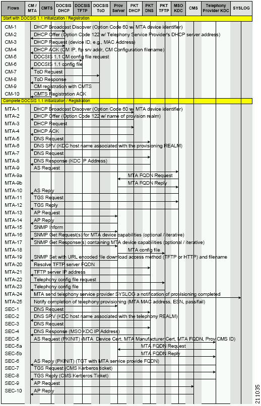
Figure 7-1 illustrates the Secure provisioning flow for PacketCable eMTAs.
Figure 7-1 Embedded-MTA Secure Power-On Provisioning Flow
Note
In addition, the content of the KDC log file is critical to understanding the root cause of any KDC failure.
When diagnosing problems in provisioning an embedded Multimedia Terminal Adapters (eMTA), the flow description in Table 7-5 helps identify which step in the PacketCable provisioning flow is failing.
Table 7-5 PacketCable Secure eMTA Provisioning
CM-1
DHCP Broadcast Discover
This is similar to the DOCSIS cable modem (CM) boot flow for DHCPv4 or DHCPv6 with DHCP options added to provide the MTA with a list of PacketCable DHCP servers from which the MTA is allowed to accept DHCP offers.
CM-2
DHCP Offer
CM-3
DHCP Request
CM-4
DHCP Ack
CM-5
DOCSIS 1.1 CM Config File Request
CM-6
DOCSIS 1.1 Config File
CM-7
ToD Request
CM-8
ToD Response
CM-9
CM Registration with CMTS (cable modem termination system)
CM-10
CMTS Registration Ack
MTA-1
DHCP Broadcast Discover
Using DHCP, the MTA announces itself as a PacketCable MTA and provides information on the capabilities and provisioning flows it supports (Secure, Basic, and so on.). The MTA also obtains addressing information and DHCP Option 122. DHCP Option 122 contains the PacketCable provisioning server address and the security realm name. This information is used to allow the MTA to contact the KDC and provisioning server.
Some key troubleshooting hints are:
•
•
•
•
•
If a packet trace reveals that the MTA is cycling between steps MTA-1 and MTA-2, there could be a problem with the configuration of DHCP Option 122 (realm name or provisioning server FQDN suboptions), DHCP Option 12 (hostname), or DHCP Option 15 (domain name).
MTA-2
DHCP Offer
MTA-3
DHCP Request
MTA-4
DHCP Ack
MTA-5
DNS Request
MTA uses the security realm name (delivered within DHCP Option 122) to perform a DNS SRV lookup on the KDC service and then resolves the KDC IP address.
Some key troubleshooting hints are:
•
•
•
MTA-6
DNS Srv
MTA-7
DNS Request
MTA-8
DNS Response
MTA-9
AS Request
The AS-REQ request message is used by the KDC to authenticate the MTA.
Some key troubleshooting hints are:
•
•
MTA-9a
MTA FQDN Request
The KDC extracts the MTA MAC address from the MTA certificate and sends it to the provisioning server for validation. If the provisioning server has the FQDN for that MAC address, it is returned to the KDC. The KDC then compares the FQDN received from the MTA to the FQDN received in the FQDN-REP reply message.
Some key troubleshooting hints are:
•
•
MTA-9b
MTA FQDN Reply
MTA-10
AS Reply (AS-REP)
The KDC grants a provisioning service ticket to the MTA and also sends the Service Provider, Local System Provider (optional), and KDC certificate to the MTA. The MTA then verifies if the certificates sent by the KDC chain to the Service Provider Root certificate stored in the MTA. If these certificates do not chain, the MTA loops back to step MTA-1 of the provisioning flow. See Using PKCert.sh, page 28-3, for additional information on the KDC.cer file.
A key troubleshooting hint: Verify if the KDC log files show that the AS-REP message was sent to the device. If a packet trace reveals the MTA is cycling between steps MTA-1 and MTA-10, there is a problem with the service provider certificate chain.
MTA-11
TGS Request
The MTA receives either a service ticket or a ticket-granting-ticket (TGT) following step MTA-10. If the MTA had obtained a TGT instead of a service ticket in step MTA-10, it contacts the ticket-granting-server (KDC) to obtain a service ticket.
MTA-12
TGS Reply
The KDC sends a service ticket in the TGS Reply to the MTA.
MTA-13
AP Request (AP-REQ)
The MTA presents the ticket (received at step MTA-10) to the provisioning server specified by DHCP Option 122.
MTA-14
AP Reply (AP-REP)
The provisioning server uses the KDC shared secret to decrypt the AP-REQ, validates the provisioning server ticket presented by the MTA, and sends AP-REP with SNMPv3 keys. SNMPv3 is now authenticated and (optionally) encrypted.
MTA-15
SNMP Inform
The MTA signals to the provisioning server that it is ready to receive provisioning information.
MTA-16
SNMP Get Request
SNMPv3—If the provisioning server (DPE) requires additional device capabilities, it sends the MTA one or more SNMPv3 Get requests to obtain the required information on MTA capability. The provisioning server (DPE) may use a GetBulk request to request a bulk of information in a single message.
MTA-17
SNMP Get Response
SNMPv3—The MTA sends to the provisioning server (DPE) a response for each GetRequest that contains information on MTA capabilities requested in step MTA-16.
MTA-18
MTA Config file
Using information made available in steps MTA-16 and MTA-17, the provisioning server (DPE) determines the contents of the MTA configuration data file.
MTA-19
SNMP Set
SNMPv3—The provisioning server performs an SNMPv3 Set to the MTA containing the URL for the MTA configuration file, encryption key for the file, and the file hash value.
MTA-20
Resolve TFTP Server FQDN
DNS Request—If the URL-encoded access method contains an FQDN instead of an IPv4 address, the MTA uses the DNS server of the service provider network to resolve the FQDN into an IPv4 address of the TFTP server or the HTTP server.
MTA-21
TFTP Server IP Address
DNS Response—The DNS server returns the IPv4 IP address of the service provider network as requested in step MTA-20.
MTA-22
Telephony Config File Request
The MTA proceeds to download the VoIP configuration file from the specified TFTP server. Note that Prime Cable Provisioning integrates the TFTP server into the DPE component.
MTA-23
Telephony Config File
MTA-24
MTA Send
The MTA optionally sends a syslog notification to the service provider that provisioning is complete.
MTA-25
Notify completion of telephony provisioning
The MTA signals to the provisioning server if the new configuration is acceptable.
SEC-1 to SEC-10
These steps are the post-MTA provisioning security flow and are not applicable to
Prime Cable Provisioning provisioning. This flow involves getting Kerberos tickets associated with each CMS with which the MTA communicates. For details, see the PacketCable Security Specifications.
Configuring SRV Records in the Network Registrar DNS Server
You must configure the Network Registrar DNS server to operate with the KDC. To set up this configuration, see your Network Registrar documentation and these instructions.
Note
Step 1
Step 2
Step 3
nrcmd>zone voice.example.com create primary address_of_nameserver hostmasterwhere address_of_nameserver specifies the IP address of the name server.
Step 4
nrcmd>zone voice.example.com. addRR _kerberos._udp. srv 0 0 88 KDC_FQDNwhere KDC_FQDN specifies the FQDN of the KDC.
Step 5
nrcmd>save
nrcmd>dns reload
Configuring PacketCable 2.0
PacketCable 2.0 supports the convergence of voice, video, data, and mobility technologies. It is based on Session Initiation Protocol (SIP) and IP multimedia system (IMS) and supports configuration and management of Non-Embedded User Equipment (UE) as well as Embedded User Equipment (E-UE).
Prime Cable Provisioning supports only the UEs that are embedded with a DOCSIS Cable Modem and are called as E-UE or Embedded Digital Voice Adapter (E-DVA). E-DVA supports RST (Residential SIP Telephony.
Note
Adding a Dial Plan for PacketCable 2.0 Groovy
A dial plan is provisioned on the UE to inform the UE about how dialed digits should be interpreted. A dial plan is an ordered set of regular expressions combined with some special tokens that represent actions to be carried out by the UE when a regular expression is matched.
The dial plan is organized into a list of rules. The UE must apply the dial plan rules sequentially and upon matching a pattern, including timers, the UE must perform the specified action or actions.
To create a dial plan you must be familiar with the notation and content of Augmented Backus-Naur Form (ABNF) defined in RFC 4234. Below is a sample dial plan that you can use as a reference.
Note
A sample groovy file to create a dial plan
def dialPlan = '''TIMER S=4.000000TIMER Z=2.000000domain = "@ims.packetcable.com"dialString = ";user=dialstring"dialPhone = ";user=phone"homeEmergencyNumber = "911"localEmergencyNumber = "911"MAP MainTable ="0S" : MAKE-CALL"0#" : MAKE-CALL"00" : MAKE-CALL"(=Emergency)" : EMERGENCY-CALL("sip:" "911" =domain =dialPhone)"(=N11)" : MAKE-CALL("sip:" #1v =domain =dialString)"(=SpeedDial)" : MAKE-CALL("sip:" #1v =domain =dialString)"(=PhoneNumber)" : MAKE-CALL("sip:" #1v =domain =dialPhone)"(=ImmediateVSCs)" : RETURN"(=DelayedVSCs)" : RETURN"(x{1-20})S" : MAKE-CALL("sip:" #1 =domain =dialPhone)"(x{1-20})#" : MAKE-CALL("sip:" #1 =domain =dialPhone)'''* PKTC-IETF-MTA-MIB pktcMtaDevEnabled (1.3.6.1.2.1.140.1.1.6.0)*/configFile.add(TLV_SNMP("1.3.6.1.2.1.140.1.1.6.0", "Integer", "1"))/** Device Level Configuration (Secure flow only):* Include required Secure-flow realm TLVs*/if (isSecureProvFlowMode){// PKTC-IETF-MTA-MIB pktcMtaDevRealmName.1 (1.3.6.1.2.1.140.1.3.6.1.2.1)configFile.add(TLV_SNMP("1.3.6.1.2.1.140.1.3.6.1.2.1", "STRING", realmName))// PKTC-IETF-MTA-MIB pktcMtaDevRealmOrgName.1 (1.3.6.1.2.1.140.1.3.6.1.5.1)configFile.add(TLV_SNMP("1.3.6.1.2.1.140.1.3.6.1.5.1", "STRING", realmOrgName))}configFile.add(option.createOptionValue(OptionSyntax.SNMP,"64",[".pktcEUERSTDMValue.1","ST RING",dialPlan]));
Note
If the TLV length of Option 64 exceeds 4500, you must update the property /default/asnParser/bufferLength=20000 in /opt/CSCObac/api/conf/api.properties and in /opt/CSCObac/rdu/conf/rdu.properties.
Configuring SNMPv3 Cloning on RDU and DPE for Secure Communication with PacketCable MTAs
Prime Cable Provisioning lets you enable an external network manager for SNMPv3 access to MTA devices. Additionally, the RDU is capable of performing SNMPv3 operations in a specific MTA.
To enable this capability, set the security key material at the DPEs and RDU. After the key material has been set, the Prime Cable Provisioning application programming interface (API) calls that are used to create cloned SNMPv3 entries are enabled.
Note
Creating the Key Material and Generating the Key
Creating the key material is a two-step process:
1.
2.
Note
To create the key material:
Step 1
#generateSharedSecret.sh passwordwhere password is any password, from 6 to 20 characters, that you create. This password is then used to generate a 46-byte key. This key is stored in a file, called keymaterial.txt, that resides in the BPR_HOME/rdu/conf directory.
Step 2
Euro PacketCable
Euro-PacketCable services are essentially the European equivalent of North American PacketCable services with the following differences:
•
•
For Euro-PacketCable certificates, the kdc.ini file must have the euro-packetcable property set to true. The KDC supports Euro-PacketCable (tComLabs) certificate chains. The following is a sample Euro PacketCable-enabled KDC configuration file.
[general]interface address = 10.10.10.1FQDN = servername.cisco.commaximum log file size = 10000n saved log files = 100log debug level = 5 minimumps backoff = 150 maximumps backoff = 300euro-packetcable = trueWhen using Euro PacketCable, ensure that the value of the PacketCable property /pktcbl/prov/locale is set to EURO. The default is NA (for North America). You can specify the locale in the Configuration File utility. See Using Configuration File Utility for Template, for more information.
Euro-PacketCable MIBs
Euro-PacketCable MIBs are essentially snapshots of draft-IETF MIBs. MTA configuration files consist of SNMP VarBinds that reference the MIBs. There are substantial differences between the North American PacketCable and Euro-PacketCable MIBs; therefore, the North American PacketCable and Euro-PacketCable configuration files are incompatible. During installation, sample files for North American PacketCable (cw29_config.tmpl) and Euro PacketCable (ecw15_mta_config.tmpl) are copied to the BPR_HOME/rdu/samples directory.
Prime Cable Provisioning ships with the following Euro-PacketCable MIBs:
•
•
•
•
•
•
•
Configuring Euro-PacketCable MIBs
To configure Prime Cable Provisioning to use Euro-PacketCable MIBs, you must change the Prime Cable Provisioning RDU property that specifies the MIBs to be loaded. By default, this property contains the PacketCable MIBs.
You can change the property in one of the following ways:
•
•
•
The property name is /snmp/mibs/mibList (properties file) or
SNMPPropertyKeys.MIB_LIST(the Prov API constant name). The property value is a comma-separated value (CSV) consisting of the required MIB names, as shown:/snmp/mibs/mibList=SNMPv2-SMI,SNMPv2-TC,INET-ADDRESS-MIB,CISCO-SMI,CISCO-TC,SNMPv2-MIB,RFC 1213-MIB,IANAifType-MIB,IF-MIB,DOCS-IF-MIB,DOCS-IF-EXT-MIB,DOCS-BPI-MIB,CISCO-CABLE-SPECTR UM-MIB,CISCO-DOCS-EXT-MIB,SNMP-FRAMEWORK-MIB,DOCS-CABLE-DEVICE-MIB,DOCS-QOS-MIB,CISCO-CABL E-MODEM-MIB,DOCS-IETF-BPI2-MIB,INTEGRATED-SERVICES-MIB,DIFFSERV-DSCP-TC,DIFFSERV-MIB,TCOML ABS-MIB,PKTC-TCOMLABS-MTA-MIB,PKTC-TCOMLABS-SIG-MIBConfiguring DPoE
The DOCSIS Provisioning of Ethernet Passive Optical Network (DPoE) 1.0 is a standard for provisioning EPON access technology using the existing DOCSIS provisioning flow. DPoE network offers IP high speed data services equivalent to DOCSIS networks, where the DPoE network acts like a DOCSIS CMTS. The DPoE system and DPoE Optical Network Unit appear to act like a DOCSIS CM also known as virtual CM(vCM). Prime Cable Provisioning uses the existing DOCSIS device type for DPoE vCM devices. DPoE configuration files contain a mixture of DOCSIS and DPoE-specific TLVs.
To identify a DPoE vCM, refer to the DHCP discover data captured under Request Dictionary displayed under Device Details page. Details similar to the following example show up and if the text in bold appear in page, then it is DPoE vCM.
Example:
v-i-vendor-opts = enterprise-id 4491, (oro 1 2)chaddr = 00:00:00:00:0d:12relay-agent-info = (circuit-id 1 80:01:03:ef), (remote-id 2 00:00:00:00:0d:12), (v-i-vendor-opts 9 enterprise-id 4491, (cmts-capabilities 1 (docsis-version 1 03:00), (dpoe-system-version 1 01:00), (dpoe-system-pbb 4 10248294639d, 1a9ebee4971b, 26d07cd85ab2, 33800cf1abbb, 3b87c25dffbb, 47bd40a08f95, 4fc50b53a070, 5768bd554059, 591cf857aea1, 638c2d178f8f, 6d932a665ec9, 74efc6fc060b, 7a602d489587)))relay-agent-circuit-id = 01:04:80:01:03:efclient-id-created-from-mac-address = 0dhcp-class-identifier = AIC Echo,docsis3.0:hlen = 06giaddr = 4.0.0.1vendor-encapsulated-options = (device-serial-number 4 000000000d12), (hardware-version-number 5 v3.2.1), (software-version-number 6 v1.0.2), (boot-rom-version 7 BOOT1.0), (vendor-oui 8 000000), (vendor-name 10 XEROX CORPORATION), (dpoe-embedded-components-list 55 ECM)dhcp-parameter-request-list = {1,3,6,7,12,15,51,54,4,2,67,66}client-id = ff:00:00:00:00:00:03:00:01:00:00:00:00:0d:12Sample DPoE Configuration file
The sample DPoE configuration files are available under the installed package at location:
•
•
•
Note
See DPoE Option Support for the DPoE TLVs.
Differences between DPoE and DOCSIS Provisioning
The provisioning of a DPoE vCM is nearly identical to the provisioning of DOCSIS CM. This allows existing DOCSIS-based back-office systems (such as provisioning servers) to support DPoE vCM provisioning with minimal changes. However, there are minor differences between DPoE vCM and DOCSIS CM provisioning:
•
•
•
•
•
•
•
DPoE Workflow
DPoE workflow is same as DOCSIS workflow. See DOCSIS Workflow for details.
Configuring CableHome
This section describes the activities that must be performed to ensure a satisfactory CableHome deployment. There are two versions of the CableHome technology: secure (SNMP) and non-secure (DHCP). This chapter deals exclusively with the non-secure version.
This section assumes that you are familiar with the contents of the CableHome Specification CH-SP-CH1.0-I05-030801.
CableHome Workflow
To successfully configure Prime Cable Provisioning for provisioning using the non-secure CableHome technology, you must perform the tasks described in Chapter 6, "Configuring Prime Cable Provisioning Components", in addition to those described in this section.
Table 7-6 describes the tasks you must perform on Prime Cable Provisioning to support CableHome.
Configuring Prime Network Registrar
This section describes how to configure Prime Network Registrar, the cable modem configuration system (CMTS).
Step 1
Configure unprovisioned and provisioned client classes and scopes for cable modems, as specified in Cisco Prime Network Registrar 8.1 User Guide.
Step 2
Step 3
Step 4
Configuring RDU
To configure CableHome support on the RDU, perform these configurations:
•
•
Configuring CableHome WAN-MAN
1.
2.
–
–
Configuring CableHome WAN-Data
Configure these WAN-Data parameters whenever you want portal services to obtain the WAN-Data IP addresses:
1.
2.
Configuring DPE
To configure the DPE to support the CableHome technology:
Step 1
Step 2
•
•
Step 3
•
•