-
User Guide for the Cisco Mobile Wireless Transport Manager 6.1.5
-
Preface
-
Configuring Security
-
Overview
-
Getting Started
-
Basic Operations
-
Setting Up Your Server
-
Managing Views
-
Understanding Detailed Object Functions
-
Understanding Basic Object Functions
-
Managing Alarms and Events
-
Viewing Network Topology
-
Accessing Data from the Web Interface
-
Viewing Administrative Information from the Web Interface
-
Managing Reports
-
Editing an ITP Route Table File
-
Editing an ITP Global Title Translation Table
-
Editing ITP MLR Address Table Files
-
Client Object Map Reference
-
Command Reference
-
FAQS
-
Troubleshooting the MWTM and the Network
-
Status Definitions
-
MIB Reference
-
Trap Reference
-
Configuring MWTM to Run with Various Networking Options
-
MWTM Ports
-
Glossary
-
Index
-
 Feedback
Table Of Contents
Graphical User Interface and Web Features
How Do I Identify My Network Type?
What Is Client/Server Architecture?
Overview
This chapter describes the Cisco Mobile Wireless Transport Manager (MWTM) and contains:
•
How Do I Identify My Network Type?
•
What Is MWTM?
Using the MWTM, you can discover, manage, and troubleshoot objects in your ITP, IPRAN, and/or mSEF network. The MWTM provides:
•
Server and Network Features
The MWTM:
•
•
•
•
•
•
•
–
–
–
–
–
–
–
–
•
•
•
•
Graphical User Interface and Web Features
The MWTM:
•
•
Event Monitoring Features
The MWTM:
•
•
•
•
•
Performance Features
The MWTM:
•
–
–
–
–
•
•
Provisioning Features
The MWTM provides provisioning for ITP, IPRAN, GGSN, CSG, and HA.
The MWTM:
•
•
•
•
•
•
•
See MWTM Provision Attributes chapter of the OSS Integration Guide for the Cisco Mobile Wireless Transport Manager 6.1.5 for more information on the attributes for MWTM 6.1.5 provision feature.
Security Features
The MWTM provides:
•
•
•
•
•
•
•
•
Topology Features
The topology features are available for the ITP and RAN-O solutions.
The MWTM:
•
•
•
Troubleshooting Features
The MWTM provides:
•
•
Customization Features
The MWTM:
•
•
•
You can:
•
•
•
•
•
•
•
Integration Features
The MWTM can integrate with:
•
–
–
•
–
–
•
The MWTM:
•
•
•
What Is ITP?
The Cisco hardware and software SS7-over-IP (SS7oIP) solution includes the ITP, which provides a reliable, cost-effective medium for migrating Signaling System 7 (SS7), the telecommunications network signaling technology, to the mobile wireless industry IP environment. The ITP off-loads SS7 traffic onto the IP network, replacing the mobile service provider's signaling network with a redundant IP cloud.
In the ITP, and in the MWTM, a node is a Cisco ITP or a legacy SS7 device (SSP, SCP, or STP).
A Cisco ITP node can have multiple signaling points. Signaling points are identified with unique addresses called point codes. Point codes are carried in signaling messages that are exchanged between signaling points to identify the source and destination of each message.
Signaling points and legacy SS7 nodes are connected by links, and multiple links are grouped in a linkset. Each link is assigned to a single linkset, but each linkset can have multiple links. Links within the same linkset must be parallel between the same signaling points or nodes.
In the MWTM, a linkset is a representation of two linksets that are associated with two signaling points or nodes, one for each side of a logical connection.
An application server is a logical entity serving a specific routing key.The application server implements a set of one or more unique application server processes, of which one or more is normally actively processing traffic. An application server process is an IP-based instance of an application server, such as Call Agents, HLRs, SMSCs, and so on. An application server process can implement more than one application server.An application server process association is the ITP virtual view of an application server process. The application server process association resides and is defined on the ITP.A signaling gateway-mated pair is a pair of signaling gateways that exchange necessary state information by using the Signaling Gateway Mate Protocol (SGMP).
Collectively, nodes, signaling points, linksets, links, application servers, application server processes, application server process associations, and signaling gateway-mated pairs are known as managed objects.
For more information about ITP, including procedures for configuring ITP objects, see the IP Transfer Point (ITP) feature module for Cisco IOS software release 12.2(25)SW5 or later.
What Is CDT?
The Cisco Database for Telecommunications (CDT) is a per subscriber routing solution that supports SS7/C7 and IP-based addressing services. Alarming is provided by the master server (monitored by MWTM). An alarm event consists of a component (service or facility) name, class, and severity level, as well as detailed message information. System events include resource thresholds (throughput, database capacity, thread, etc.), network connectivity, user authentication, system availability, etc.
You can use the MWTM to discover CDT nodes and provide basic monitoring functions such as alarm status, polling information, and recent events. From the MWTM, you can launch the CDT login web page.
Note
What Is IPRAN?
The Cisco IP Radio Access Network (IPRAN) delivers standards-based end-to-end, IP connectivity for RAN transport. The Cisco solution converts RAN voice and data frames into IP packets at the cell site, and transports them seamlessly over a backhaul network. At the central site, the RAN frames are extracted from IP packets, and the ATM or TDM streams are rebuilt. The result is a transparent, radio vendor-agnostic, RAN IP transport solution.
The Cisco IPRAN solution is also known as Mobile Transport over Pseudowires, or MToP. For more information about MToP, see:
http://www.cisco.com/en/US/netsol/ns732/networking_solutions_solution.html
There are two families of pseudowire protocols used within the Cisco IPRAN: PWE3 and RAN-O.
What Is PWE3?
Pseudowire Emulation Edge to Edge, or PWE3, is the emulation of an ATM or TDM service over IP, MPLS, or L2TPv3 transport. The PWE3 protocol family is used to encapsulate RAN voice and data frames at the cell site for transport over a backhaul network.
Cisco nodes that support PWE3 and are managed by MWTM include:
•
–
–
•
What Is RAN-O?
Radio Access Network Optimization (RAN-O) delivers standard-based, end-to-end, IP connectivity for GSM and UMTS RAN transport. The solution Cisco offers frames RAN voice and data frames into IP packets at the cell-site, and transports them seamlessly over an optimized backhaul network. At the central site, the RAN frames are extracted from IP packets and the Abis or Iub data streams are rebuilt. The result is a transparent, radio vendor-agnostic, RAN IP transport and optimization solution that delivers nominal optimization efficiency of 50% without any impact on voice quality.
In RAN-O and in the MWTM, a node is a Cisco RAN-O device. A RAN node can be one of the following:
•
–
–
•
•
•
Note
RAN interfaces that are available on the nodes interconnect nodes in a RAN-O network. A Cisco RAN-O node can have multiple RAN interfaces.
Cards are the modules that reside in the Cisco ONS 15454 SONET multiplexer.
IP backhauls are the trunks that transport optimized voice and data traffic between a remote cell-site RAN-O node and an aggregation RAN-O node at a central site.
RAN shorthauls are the interfaces that transport GSM or UMTS voice and data traffic between the Base Transceiver Station (BTS) or Node-B and the RAN-O node at the cell site. At the aggregation site, RAN shorthauls exist between the RAN-O node and the BSC or RNC.
RAN backhauls describe the end-to-end RAN connections between the BTS or Node-B at the cell site and the BSC or RNC at the aggregation site.
Collectively, nodes, interfaces, cards, and RAN backhauls and shorthauls are known as managed objects.
For more information about RAN-O objects, see:
•
•
http://www.cisco.com/en/US/products/ps9395/products_installation_and_configuration_guides
_list.html•
What Is mSEF?
The Cisco Mobile Internet, also known as mobile Services Exchange Framework (mSEF), provides standards-based framework to enable the mobile Internet that links the RAN to IP networks and the services they provide. The mSEF provides:
•
•
•
The mSEF gateways that the MWTM manages include:
•
–
–
•
•
•
•
•
•
•
What is LTE?
Long Term Evolution (LTE) is the next generation (4G) mobile wireless system expected to revolutionize mobile broadband usage. It is the next step beyond the current, 3G UMTS technology. LTE provides:
•
•
•
•
•
Cisco is focused on developing the PDN Gateway (PDNGW), a Mobility Anchor gateway for inter-access technology mobility, and the Serving Gateway (SGW), a Mobility Anchor gateway for intra-3GPP mobility, for the LTE market.
The PDNGW provides connectivity to the UE to external packet data networks by being the point of exit and entry of traffic for the UE. The PDNGW performs authentication, IP address allocation, policy enforcement, packet filtering for each user, charging support, lawful interception, and packet screening.
The SGW is the gateway that terminates the interface towards the E-UTRAN (Enhanced Universal Terrestrial Radio Access Network) (S1). It acts as the local mobility anchor for inter-e Node B and inter-3GPP handovers (relaying traffic between 2G/3G networks and PDN GW).
The MWTM:
•
•
•
•
How Do I Identify My Network Type?
The MWTM can manage one or more types of networks. To determine the type of network that the MWTM is managing, launch the MWTM (by using either the MWTM client or web interface), and observe the network type or types in the title bar.
You can also click on a node in the left tree of the MWTM main window to view detailed information about the node in the right pane. The Node Type and other information provide enough details to determine the type of network you are managing.
If you are using the MWTM to manage multiple network types, you can uniquely identify node types by the DNS host names that you assign to them. For example, you can incorporate the string itp into the hostname of an ITP node (as in itp-75). Similarly, IPRAN nodes can employ a unique host naming scheme (for example, rano-34). In addition, you can segregate the nodes of different network types into different management subviews with, for example, one subview for ITP and another subview for IPRAN nodes. For more information about creating views and subviews, see Chapter 6, "Managing Views".
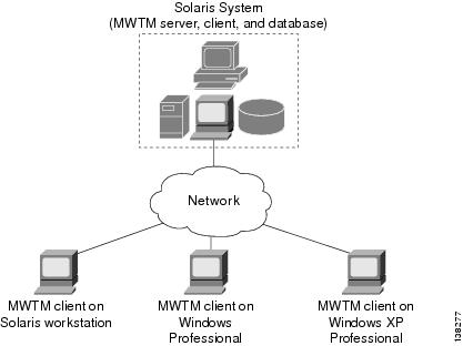
What Is Client/Server Architecture?
The MWTM provides central services and database functions on an MWTM server, which communicates through a messaging interface with multiple MWTM clients.
The MWTM supports a maximum of 50 clients per MWTM server.
The MWTM comprises server and client software components that can be installed on the same workstation or on different workstations. The MWTM server is currently available on Solaris and Linux. The MWTM client is available on Solaris and Windows XP Professional.
Figure 1-1 MWTM Client/Server Architecture
Note
The client/server architecture is cross-platform compatible, with which you can run the client and server software in mixed operating system environments. For example, you can run the MWTM server on a Solaris or Linux workstation, and access it from an MWTM client running on Windows XP Professional.
The MWTM server software comprises a group of functional services that manage the data among the network, client workstations, and the centralized database. The MWTM server manages the exchange of data between the MWTM database and the network nodes. The MWTM process manager launches and manages all of the MWTM server processes, providing a robust and reliable launching platform for the MWTM.
The MWTM client software communicates with the MWTM server. You can install the MWTM client software on the same workstation as the MWTM server software, or on a different workstation on the same network as the MWTM server. After you install the MWTM server, you can download the MWTM client software from the web, for easy distribution to users and easier access to important information.
Note