-
Cisco CNS Configuration Engine Administrator Guide, 1.3
-
Preface
-
Product Overview
-
Configuring the CNS 2100 Series System
-
Cisco CNS Configuration Engine Administration for Internal Directory Mode
-
Cisco CNS Configuration Engine Administration for External Directory Mode
-
Directory Administration Tool
-
Troubleshooting
-
Country Codes
-
Software Licenses and Acknowledgements
-
Index
-
 Feedback
Table Of Contents
Installing the Software and Configuring the Cisco CNS 2100 Series Intelligence Engine
Internal Directory Mode Setup Prompts
External Directory Mode Setup Prompts
How to Verify the Configuration on the CNS 2100 Series System
How to Verify the Installation of the Cisco CNS Configuration Engine
Migrating DCL Data and Templates from Release 1.2 to 1.3
Export Data Onto a Remote FTP Site
Migrate Data and Setup the CNS 2100 Series System
XML Transform Tool for Users Migrating from Release 1.2 to 1.3
Importing Groups and Devices from Release 1.2 to 1.3
How to Revert to Factory Setting
How to Reconfigure System Network Information
How to Recover and Redefine Your Root Password
Installing a Replacement CNS 2100 Series System
How to Install a Replacement System
How to Restart the Cron Daemon
Initializing Tivoli Management Agent
Register and De-register Tivoli Agent to System Start and Stop Service
How to Verify the TMA is Running
Installing the Software and Configuring the Cisco CNS 2100 Series Intelligence Engine
This chapter describes how to install the Cisco CNS Configuration Engine 1.3 software and configure the Cisco CNS 2100 Series Intelligence Engine.
Installing the Software
The Cisco CNS Configuration Engine 1.3 software is contained on a CD-ROM that is in the accessory kit.
To be able to monitor the installation activity, you should have a local keyboard-mouse and a VGA screen to your system C2T (out) port using a K/M/V (keyboard, mouse, VGA cable (IBM P/N 00N6954).
To install the software, follow these steps:
Step 1
Verify that the CNS 2100 Series system is powered down.
Step 2
Step 3
The software installs automatically. When the install sequence completes, the system automatically ejects the CD-ROM and restarts into Linux from the hard drive.
Step 4
Running the Setup Program
You must run the Setup program when you start the system for the first time.
You must connect to the system using the serial port to use the Setup program. The parameters for using the serial port are 9600-N-8-1. Alternatively, you can connect a VGA monitor to the CNS 2100 Series.
If this is the first time running Setup, or you have just run reinitialize or relocate, you cannot connect to the system using Telnet. Telnet is only possible if the network interfaces are configured.
To run Setup, follow these steps:
Step 1
When the system finishes the startup routine, a login prompt appears.
Step 2
The Setup program starts.
Step 3
For information about valid values for each parameter, see Table 2-1 through Table 2-9.
Use the following conventions when running the Setup program:
•
After you enter a response, you cannot edit it again. To change an entered response you must exit the Setup program and enter your responses again. You can exit the Setup program in two ways:
–
The login prompt appears. Use the login setup to run the Setup program.
–
The Setup program exits without saving the configuration, then restarts.
•
Step 4
For an example of the Internal Directory mode prompts, see "Internal Directory Mode Setup Prompts"on this page.
For an example of the External Directory mode prompts, see "External Directory Mode Setup Prompts" section.
Step 5
Step 6
After you save the configuration, the shell prompt appears.
How to Re-execute Setup
You cannot run Setup a second time by logging in as setup because that account is disabled for security reasons after it is used once successfully. To re-execute Setup, login as root, then enter the setup command in the shell prompt.
Internal Directory Mode Setup Prompts
The following sample shows the standard set of prompts for Internal Directory mode:
Entering Network Appliance SetupType ctrl-c to exitFor detail information about the parameters in this setup, refer to "CiscoIntelligence Engine 2100 Series Configuration Engine Administrator's Guide".Interactive or non-interactive setup? 0=interactive, 1=non-interactive. 0Note: Modular router support is available only in internal directory mode.Choose operational mode of system. 0=internal directory mode, 1=external directory mode. 0Please enter the password you would like to use as the root password for theIE2100. Warning: If you lose this password, the root account will be locked outof maintaining the IE2100.Enter root password: ******Re-enter root password: ******Enter hostname: rainEnter domain name: cisco.comUser-level shell account for IE2100 has read-only monitoring and troubleshooting.However, no configuration changes are possible with this account.Enter username for user-level shell account: adminEnter password for user-level shell account: *****Re-enter password for user-level shell account: *****You must configure eth0 or eth1. Press <Enter> to skip!Enter eth0 IP address: 10.1.19.12Enter eth0 network mask: 255.255.255.0Enter eth0 default gateway IP address: 10.1.19.6Enter eth1 IP address:Enter primary DNS server IP address: 171.68.226.120Enter secondary DNS server IP address (optional):Enter country code: usEnter company code: ciscoConfiguration Engine user ID is used to log in to the web-based GUI and managenetwork device objects and templates. This account does NOT have shell access.Enter Configuration Engine login name: adminEnter Configuration Engine login password: *****Re-enter Configuration Engine login password: *****Enter internal LDAP server password: *****Re-enter internal LDAP server password: *****Encryption settings:------------------------Enable cryptography (crypto) between Event Gateway(s)/Config Server and device(s) (y/n)? [y]Certificates already exist. Overwrite (y/n)? [y]Enter certificate FTP server (hostname.domainname or IP address): [ringer]Enter username used for FTP server: [anrichar]Enter FTP password: [********]Re-enter FTP password: [********]Enter absolute pathname of remote key file: [/users/anrichar/cert/server.key]Enter absolute pathname of remote certificate file: [/users/anrichar/cert/server.crt]Enabling plaintext operation will increase security risk.Enable plaintext between Config Server and devices/GUI administration (y/n)? [n] yEnable plaintext operation between Event Gateway and devices (y/n)? [n] yAuthentication settings:-----------------------------IOS Devices are normally authenticated before being allowed to connect to theEvent Gateway/Config Server. Disabling authentication will increase security risk.Enable authentication (y/n)? [n] yEvent services settings:-----------------------------Enter NSM directive (none, default, http): [default]Enable Event Gateway debug log (y/n)? [n]Each Event Gateway process serves 500 devices. Maximum number of Event Gatewaysallowed is 11.Enter number of Event Gateways that will be started with crypto operation: 10Enter number of Event Gateways that will be started with plaintext operation: [0]1Enter CNS event bus network parameter: [rain]Enter CNS event bus service parameter: [7500]Current settings for IMGW:---------------------------------Gateway ID: rainRun as daemon (y/n)? yTimeout in seconds for entire Telnet operation to complete: 180Timeout in seconds between prompts during Telnet session: 60Concurrent Telnet session limit: 100Remove temporary logs of Telnet sessions into devices (y/n)? yLocation of temporary logs of Telnet sessions into devices: /tmpHoptest success retry interval (sec): 7200Hoptest failure retry interval (sec): 3600Logging level (verbose, error, silent): errorLog file prefix: IMGW-LOGLog file size (bytes): 50331648Log file rotation timer (minutes): 60Logging mode (append, overwrite): appendRe-configure IMGW (y/n)? [n]Parameter Descriptions
Interactive or non-interactive setup: In interactive setup, you set up the appliance by entering all configuration inputs manually. In non-interactive setup, you download a configuration file that can be run and set up the box automatically.
Internal/external directory mode: Internal Directory mode uses the embedded directory service. External Directory mode uses an external directory service.
Root password: This is the password for logging into the root-user account of Linux. Setup prompts you to redefine the root password whenever it detects that the root password is set to the factory default blender. Later, you can change root password using the Linux password command passwd.
Hostname: The name of the CNS 2100 Series system.
Domain name: The name of the domain in which the CNS 2100 Series system exists.
Username/password for user-level shell account: This is the username-password pair to be created in Linux for administrative purpose. This account does not have root privileges.
Eth0/Eth1 IP address/network mask: IP address and network mask of the system. You can configure one or both Ethernet card(s) for network connectivity.
Default gateway IP address: This is the gateway IP address that makes up the default route in the routing table.
Primary/secondary DNS server IP address: This is the server that provides domain-name to IP address translation service. Only the first one is required. The second one is optional.
Country/company code: These are the information used to define the internal storage structure of DCL.
Configuration Engine login name/password: Defines the administrator account and password for accessing the configuration server user interface.
Enter internal LDAP server password: Defines internal-directory-account password for the two internal administrative users: dcdadmin and cdauser1.
•
•
•
–
–
–
–
•
–
–
–
•
•
Encryption Settings
Enable cryptography (crypto) between Event Gateway(s)/Config Server and device(s) (y/n): This option enables crypto (SSL) operation. The web server listens on TCP port 443, and responds to https requests (https://machine/config/login.html). The event gateway listens to ports 11012, 11014, and so on (depending on the number started).
All data between the IE2110 and the far end are encrypted. The SSL protocol (combined with valid certificates) ensures that the IE2110 is authenticated by the far end. In order to complete SSL configuration, valid certificates need to be placed on the IE2110 (see "Configuring SSL Certificates" section).
If disabling crypto operation, the remaining prompts in this section are omitted.
Certificates already exist, Overwrite (y/n): If a certificate already exists, choose whether to download and overwrite the existing one. If there is no certificate initially on the system, this prompt is disabled.
Certificate FTP server: Specifies the location of the FTP server for downloading the certificate. Input can either be an IP address or in the form of hostname.domain. For the latter case, the DNS entered earlier is used for the hostname.domain-to-IP address resolution.
Username/password for FTP server: Specifies the login name and password for accessing the FTP server.
Absolute pathname of remote key file and certificate file: Specifies the locations of the key and certificate files on the FTP server.
Enable plaintext between Config Server and devices/GUI administration (y/n): This option enables plaintext configuration server operation. In addition to listening on TCP port 443 for crypto connection (https://machine/config/login.html), the web server also listens on TCP port 80 for plaintext connection, responding to http requests (http://machine/config/login.html).
Note
Enable plaintext operation between Event Gateway and devices (y/n): This prompt enables/disables the prompt: number of Event Gateways that will be started with plaintext operation, which appears under Event service settings.
Authentication settings
Enable Authentication (y/n): Enables Cisco IOS device authentication mechanism within the IE2110.
Note
Table 2-3 Valid Values for Authentication Parameters
Enable authentication
y, n
Event Service Settings
NSM directive: Defines NameSpace Mapper mapping modes. Valid modes are http, none, and default (see "NSM Modes" section). If input to NSM directive is http, you must answer the Event Gateway application parameters prompt (see "Setting NSM Directive to http" section).
Event Gateway debug log: Turns on Event Gateway debug logging.
Number of Event Gateways that will be started with crypto operation: Specifies the number of Event Gateway processes that should be started in crypto mode (the number of Event Gateways that communicate with devices using SSL). If crypto operation is disabled, this prompt is also disabled.
Number of Event Gateways that will be started with plaintext operation: Specifies the number of Event Gateway processes that should be started in plaintext mode (the number of Event Gateway that communicate with devices without using SSL). The total number of Event Gateways, whether it is started for crypto operation or not, should not exceed 11.
CNS Event Bus Network Parameter: Specifies the outbound network interface of CNS 2100 Series for publishing events. It can be an IP address, the name of the local network interface, a hostname, or multicast address.
CNS Event Bus Service Parameter: Specifies the ports used for publishing and listening to events.
Timesaver
Re-configure IMGW: This y/n prompt determines whether setup should display the section of prompts for re-configuring IMGW related parameters. Regular users should always answer n.
•
eth0 network onlyeth0;224.1.1.1 one multicast groupeth0;224.1.1.1,224.1.1.5;224.1.1.6 two multicast groups, send address–
–
–
Setting NSM Directive to http
The previous prompt example has NSM directive set to default. When the NSM directive is set to http, you are prompted for an additional namespace parameter, Enter Event Gateway application parameter(s) for NSM:
Enter NSM directive (none, default, http): [default] httpEnter Event Gateway application parameter(s) for NSM: [config]The new prompt definition and input format is as follows:
Event Gateway application parameter(s) for NSM: Specifies the application namespace to be used in NameSpace Mapper for resolving mapping. The default namespace used is config.
Table 2-5 Valid Values for NSM Directive Parameter
Event Gateway application parameters
Alphanumeric, dash, space
1æunlimited
Re-configure IMGW Parameters
This section shows the set of prompts required for re-configuring the IMGW settings.
Re-configure IMGW (y/n)? [n] yEnter Gateway ID: [rain]Run as daemon (y/n)? [y]Enter timeout in seconds for a CLI command to complete: [180]Enter timeout in seconds to get the next prompt in Telnet session: [60]Enter concurrent Telnet session limit: [100]Remove temporary logs of Telnet sessions into devices (y/n)? [y]Enter location of temporary logs of Telnet sessions into devices: [/tmp]Enter hoptest success retry interval (sec): [7200]Enter hoptest failure retry interval (sec): [3600]Enter logging level (verbose, error, silent): [error]Enter log file prefix: [IMGW-LOG]Enter log file size (bytes): [50331648]Enter log file rotation timer (minutes): [60]Enter logging mode (append, overwrite): [append]Parameter Descriptions
Gateway ID: Unique identifier assigned to the IMGW process. It is always set to hostname by default.
Run as daemon: Set to y for normal use. n is only used for debugging purpose.
Timeout in seconds for a CLI command to complete: The maximum waiting time in seconds for a CLI to complete.
Timeout in seconds to get the next prompt in Telnet session: The maximum waiting time in seconds to get the next prompt in Telnet session.
Concurrent Telnet session limit: The maximum simultaneous Telnet connections that IMGW supports.
Remove temporary logs of Telnet sessions into devices: The y/n value that determines if IMGW should remove the temporary files it creates for download/exec.
Location of temporary logs of Telnet sessions into devices: File system location where IMGW should create the temporary files.
Hoptest success retry interval: Time interval in minutes for IMGW to check device in the Success list (devices for which connectivity-check succeeded).
Hoptest failure retry interval: Time interval in minutes for IMGW to check device in the Failure list (devices for which connectivity-check failed).
Logging level: Verbose mode logs both error and debugging messages. Error mode logs only error messages. Silent mode does not log any message.
Log file prefix: A prefix used to construct the name of the log file. The resulting filename is made up of the prefix and the IMGW gateway ID.
Log file size: Log file size that triggers log rotation.
Log file rotation timer: Time in seconds after which to check log-file size for log rotation.
Logging mode: Select whether to append new log to the end of the log file or overwrite the previous log.
External Directory Mode Setup Prompts
Most of the prompts in External Directory mode are identical to those for the Internal Directory mode except for the introduction of the External Directory mode settings and sample schema.
In the External Directory mode, the system is configured to contact the external directory storage for device information. Certain information that makes up the schema of the external directory such as attribute names (in the device class) and container locations must be entered during Setup.
To simplify the inputs, you can choose to use the predefined sample schema and construct your external directory accordingly.
The sample shows the prompts for External Directory mode where the sample schema is enabled.
Entering Network Appliance SetupType ctrl-c to exitFor detail information about the parameters in this setup, refer to "CiscoIntelligence Engine 2100 Series Configuration Registrar Administrator's Guide".Interactive or non-interactive setup? 0=interactive, 1=non-interactive. 0Note: Modular router support is available only in internal directory mode.Choose operational mode of system. 0=internal directory mode, 1=external directory mode. 1Please enter the password you would like to use as the root password for theIE2100. Warning: If you lose this password, the root account will be locked outof maintaining the IE2100.Enter root password: ******Re-enter root password: ******Enter the hostname: rainEnter the domain name: cisco.comUser-level shell account for IE2100 has read-only monitoring and troubleshooting.However, no configuration changes are possible with this account.Enter username for user-level shell account: adminEnter password for user-level shell account: *****Re-enter password for user-level shell account: *****You must configure eth0 or eth1. Press <Enter> to skip!Enter eth0 IP address: 10.1.19.12Enter eth0 network mask: 255.255.255.0Enter eth0 default gateway IP address: 10.1.19.6Enter eth1 IP address:Enter primary DNS server IP address: 171.68.226.120Enter secondary DNS server IP address (optional):Enter country code: usEnter company code: ciscoEncryption settings:------------------------Enable cryptography (crypto) between Event Gateway(s)/Config Server and device(s) (y/n)? [y]Certificates already exist. Overwrite (y/n)? [y]Enter certificate FTP server (hostname.domainname or IP address): [ringer]Enter username used for FTP server: [anrichar]Enter FTP password: [********]Re-enter FTP password: [********]Enter absolute pathname of remote key file: [/users/anrichar/cert/server.key]Enter absolute pathname of remote certificate file: [/users/anrichar/cert/server.crt]Enabling plaintext operation will increase security risk.Enable plaintext operation between Config Server and devices/GUI administration (y/n)? [n] yEnable plaintext operation between Event Gateway and devices (y/n)? [n] yAuthentication settings:------------------------------IOS Devices are normally authenticated before being allowed to connect to theEvent Gateway/Config Server. Disabling authentication will increase security risk.Enable authentication (y/n)? [n] yEvent services settings:-----------------------------Enter NSM directives (none, default, http): [default]Enable Event Gateway debug log (y/n): [n]Each Event Gateway process serves 500 devices. Maximum number of Event Gateways allowed is 11.Enter number of Event Gateways that will be started with crypto operation: 10Enter number of Event Gateways that will be started with plaintext operation: [0]1Enter CNS event bus network parameter: [rain]Enter CNS event bus service parameter: [7500]External directory settings:---------------------------------Enter IP address of remote directory server: 10.10.18.7Enter port number of remote directory server: 389Enter external directory server login name: adminEnter external directory server password: *****Re-enter external directory password: *****Enter User DN: cn=admin,o=butterflyEnter CNS context: ou=cns,o=butterflyUse sample schema (y/n): [y]Current settings of IMGW:---------------------------------Gateway ID: rainRun as daemon (y/n)? yTimeout in seconds for a CLI command to complete: 180Timeout in seconds to get the next prompt in Telnet session: 60Concurrent Telnet session limit: 100Remove temporary logs of Telnet sessions into devices (y/n)? yLocation of temporary logs of Telnet sessions into devices: /tmpHoptest success retry interval (sec): 7200Hoptest failure retry interval (sec): 3600Logging level (verbose, error, silent): errorLog file prefix: IMGW-LOGLog file size (bytes): 50331648Log file rotation timer (minutes): 60Logging mode (append, overwrite): appendRe-configure IMGW (y/n)? [n]Parameter Descriptions
These parameter descriptions are for those parameters unique to the External Directory mode. The general parameter descriptions for the sample above (common to both modes) are listed beginning with "Parameter Descriptions" section.
IP address of remote directory server: The location of the external directory expressed as IP address.
Port number of remote directory server: The service port number of the external directory.
Remote directory server login name: Directory user that has the administrative privileges for all objects under CNS context; for example, admin.
Remote directory server password: Directory user password. This same password is also used to define the passwords of two internal administrative accounts (dcdadmin and cdauser1) of the internal directory storage.
User DN: The complete distinguished name for the remote directory administrative user.
CNS context: Directory context (DN) under which all CNS objects are created. This includes device objects, group objects, application objects, and event objects. These objects can be created inside containers under CNS context.
Use sample schema: Select y for enabling the predefined sample schema and n for otherwise. See "Sample Schema" for the definition and default values of sample schema.
Sample Schema
Table 2-8 lists the parameters and default values that define the sample schema:
This sample shows the schema prompts that need to be answered when sample schema is disabled:
Use sample schema (y/n): nEnter container name under which device objects are stored: [ou=CNSDevices]Enter container name under which group objects are stored: [ou=CNSGroups]Enter container name under which application objects are stored: [ou=CNSApplications]Enter objectclass for device object: [deviceclass]Enter template attribute name in device objectclass: [IOSconfigtemplate]Enter config id attribute name in device objectclass: [IOSConfigID]Enter event id attribute name in device objectclass: [IOSEventID]Enter CNS group attribute name in device: [parent]Enter CNS password attribute name in device object class: [AuthPassword]Enter objectclass for bootstrap password object: [CNSBootstrapPwdClass]Enter bootstrap password attribute name in bootstrap password objectclass: [CNSBootPassword]Parameter Descriptions
Device objects container name: The container in the directory under which device objects are created.
Groups objects container name: The container in the directory under which group objects are created.
Application objects container name: The container in the directory under which application objects are created.
Object class: The name of the user defined object class for device object.
Template attribute name: Attribute of the device class (as specified in the Object-class prompt) that specifies the template file for the device object. This is not the template file itself, just the name of the attribute that has the value of the template filename.
Config ID attribute name: Attribute of the device class that uniquely identifies the device in the config-server domain.
Event ID attribute name: Attribute of the device class that uniquely identifies a device within the Event Gateway server.
CNS group attribute: The attribute of the device class that specifies the group(s) to which the device object belongs. Note that this is only an attribute name, but not the groups themselves. In addition, it is required only when NSM directive is set to http mode.
CNS password attribute name in device object class: The attribute of the device class that stores the value that the CNS 2100 Series expects as the CNS password from the Cisco IOS device. If disabling authentication, this prompt is disabled.
objectclass for bootstrap password object: The name of the user defined object class for the bootstrap password object. If disabling authentication, this prompt is disabled.
Bootstrap password attribute name in bootstrap password object class: The attribute of the bootstrap password class that stores the value that the CNS 2100 Series system uses as the bootstrap password. If disabling authentication, this prompt is disabled.
Non-Interactive Setup
For non-interactive Setup, a Perl script for setting up CNS 2100 Series must be created and stored on a remote FTP server.
Sample Scripts
Two sample scripts are provided for non-interactive mode. They are internaldir.pl used for internal-directory mode and externaldir.pl for external-directory mode. They are installed in the directory /opt/CSCOcnsie/bin of CNS 2100 Series. They can be used as a template for crafting a specific setup.
The sample scripts are basically setup scripts without prompts; in other words, a non-interactive setup script. All required inputs are hard-coded in the variable initialization section. For ease of identification, associated prompts are listed as comments before each variable assignment.
Upon receiving the non-interactive setup script, it is executed and performs the followings:
1.
2.
3.
General Guidelines
Here are some general guidelines for the non-interactive Setup:
•
•
•
$rootpassword="blender";or
$rootpassword=do_decrypt("52616e646f6d49565b909053af1db595ca8823f2ddf29317");where the encrypted password is generated as follows:
[root@rain106 /root]# encrypt blender52616e646f6d49565b909053af1db595ca8823f2ddf29317[root@rain106 /root]#encrypt is a Perl script that takes a plaintext string input from stdin and generates the associated, encrypted string at stdout.
Note
•
•
•
Encryption Settings
If variable $enable_ssl is n (disable crypto), $plaintext_httpd must be set to y so that httpd (the web server) listens on port 80 (the plaintext port). If $enable_ssl is y (enable crypto), $cert_overwrite (a y/n prompt) must be defined to indicate whether to download new certificate and key. If defined y, all related FTP server information (such as $cert_ftp_server, $cert_ftp_username, $cert_ftp_user_password, $cert_ftp_keyfilename, $cert_ftp_crtfilename) must be provided or else, they can be omitted.
Event Services Settings
•
•
•
External Directory Settings
The current schema definition provided in externaldir.pl defines sample schema (see Section "Sample Schema" section).
Other Information
•
•
•
•
Configuring SSL Certificates
To configure SSL, you must generate a valid certificate:
Step 1
% openssl genrsa -out server.key 1024% chown root:root server.key% chmod 400 server.key% openssl req -new -key server.key -out server.csrStep 2
Step 3
Assuming that the signed file is server.crt, then the files server.key and cerver.crt are transferred (FTP) into the CNS 2100 Series as part of its setup process.
Note
How to Verify the Configuration on the CNS 2100 Series System
After you run the Setup program, verify that the CNS 2100 Series system is configured correctly:
Step 1
If you cannot log in, refer to the "Cannot Log In to the System" section for troubleshooting information.
Step 2
# nslookup <dns_name>where <dns_name> is the DNS name of a host that is registered in DNS. If the system cannot obtain the IP address of the host from DNS, run the Setup program again and verify the correct IP address for the DNS Server(s).
Step 3
# ping <ip_address>where <ip_address> is the IP address of a host that is accessible on the network. A DNS server is an excellent host to ping because it should always be running and accessible.
If the system cannot communicate with the network, refer to the "System Cannot Connect to the Network" section for troubleshooting information.
Step 4
Step 5
Enter the system IP address in a web browser.
For example, if the system IP address is 10.1.58.5, in a web browser enter the URL http://10.1.58.5/config/login.html. If plain text has NOT been enabled for the configuration server, enter https://10.1.58.5/config/login.html.
If you cannot connect to the system using a web browser, refer to the "Cannot Connect to the System Using a Web Browser" section for troubleshooting information.
Step 6
How to Verify the Installation of the Cisco CNS Configuration Engine
Once the system has been installed, you can verify the installation of the Cisco CNS Configuration Engine by following these steps:
Step 1
The Cisco CNS Configuration Engine supports Microsoft Internet Explorer 5.0 or Netscape 4.7 or later.
Step 2
For example: http://<ip_address>
where: <ip_address> is the IP address you entered during CNS 2100 Series system Setup. You can use the hostname if the name has been defined and registered within your DNS domain.
Note
The Cisco CNS Configuration Engine login page appears (see Figure 2-1).
Step 3
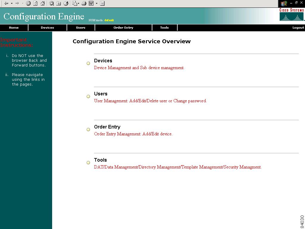
The Home page appears (see Figure 2-2).
If you have reached the Cisco CNS Configuration Engine Home page, you have verified the successful installation on the Cisco CNS Configuration Engine.
Figure 2-1 Login Page
Figure 2-2 Internal Directory Mode Home Page
Migrating DCL Data and Templates from Release 1.2 to 1.3
The migration utility provides a mechanism for upgrading your CNS 2100 Series environment from Release 1.2 to Release 1.3. The utility contains some Perl and Unix shell scripts that help carry out a data migration process. It is a three step process:
1.
2.
3.
Here are the details of each steps:
Export Data Onto a Remote FTP Site
Before exporting the data, it is assumed that the CNS 2100 Series system has already been setup and is up running.
To export your system data onto a remote FTP site, follow these steps:
Step 1
Step 2
mount /mnt/cdrom
Step 3
/mnt/cdrom/DataExport
Step 4
./dataexport.
Step 5
Install Release 1.3 Software
To re-image the system, while the Release 1.3 CD-ROM is still in the CD drive, at the command line,
Step 1
[root@abhishek-storm bin]#sync[root@abhishek-storm bin]#syncStep 2
Migrate Data and Setup the CNS 2100 Series System
After the system restarted from the new installation, the following prompts appear:
This Appliance is not configured.Please login as setup to configure the appliance.localhost.localdomain login:To migrate data and setup the CNS 2100 Series system, follow these steps:
Step 1
Step 2
datamigrate
The script proceeds in three stages:
1.
2.
3.
Your interface with the first stage is shown below. It employs the same interface as the non-interactive setup, except it also allows the use of eth1 (see "Non-Interactive Setup" section).
You must configure eth0 or eth1. Press <Enter> to skip!Enter eth0 IP address: 10.1.19.102Enter eth0 network mask: 255.255.255.0Enter eth0 default gateway IP address: 10.1.19.6Enter FTP server (hostname.domainname or IP address): sername.cisco.comEnter DNS server IP address: 171.69.226.120Enter username used for FTP server: smithEnter FTP password: *****Re-enter FTP password: *****Enter absolute pathname of data file on FTP server: /users/smith/migration.tar
XML Transform Tool for Users Migrating from Release 1.2 to 1.3
An XML transformation script is added to DAT for automating the XML file conversion process that takes care of the following two problems:
•
•
Usage
For XML file conversion, run the following shell script on the CNS 2100 Series console:
/opt/CSCOdat/XMLTransform/datxmltransformer.sh <Path to old xml> <true | false>The system generates an XML file conforming to 1.3 DTD with the same data. The shell script takes two input arguments. The first one specifies the absolute pathname to the old (1.2) XML file. The second one, if set to true, starts the conversion of IOSDeviceID to IOSConfigID; default is false if omitted.
For example, given an XML file say "Bulkdata.xml" in release 1.2 DTD format, here is the list of steps for the conversion:
Step 1
Step 2
/opt/CSCOdat/XMLTransform
Step 3
./datxmltransformer.sh ./Bulkdata.xml
The XML that is to be converted (Bulkdata.xml) must be present on the CNS 2100 Series system. The script creates a new file with the name "Bulkdata-new.xml" in the same directory as the old file. This file conforms to release 1.3 DTD. You can use it to upload the Bulkdata in Cisco CNS Configuration Engine 1.3.
Importing Groups and Devices from Release 1.2 to 1.3
In Configuration Registrar 1.2 all devices are stored in the DCL directory in the Internal Directory (Standalone) mode. In this configuration, the only NSM mode supported is default mode.
In Cisco CNS Configuration Engine 1.3, Internal Directory mode, all NSM modes (none, default, and http algo/non-algo) are supported.
When you import groups from a Release 1.2 system to a Release 1.3 system, and the Release 1.3 system is setup in NSM default mode, devices in the default group and imported groups can receive configurations sent to them. However, when the Release 1.3 system is setup in the NSM http mode, sending events to the imported groups (non-default groups) fail.
For imported groups to work in Release 1.3 (NSM http mode), you must create a reference for the imported group to an application namespace. The reason is, that NSM http mode was not available in Release 1.2 Internal Directory (Standalone) mode.
The value for the application namespace is set during Setup with the prompt:
Enter the Event Gateway Application Parameter:By default value for this parameter is config. You can override this value during Setup with one of your own.
To create the reference to an application namespace (config by default) for an imported group, follow these steps:
Step 1
Step 2
See "Management Tools" section.
Step 3
Step 4
Step 5
See "How to Manage Groups" section.
Step 6
See "Modifying Groups" section.
Step 7
Note
See "How to Add Applications to a Group" section.
Step 8
Step 9
How to Revert to Factory Setting
To revert to factory settings, follow these steps:
Step 1
For information about backup, see "Backup and Restore" section.
Step 2
Use your root password.
Step 3
This program clears your system configuration and returns you to Setup.
Step 4
How to Reconfigure System Network Information
To reconfigure system network information, such as CNS 2100 Series system IP address and hostname, follow these steps:
Step 1
Use your root password.
Step 2
This program performs the same tasks as reinitialize, except that it backs up all data that you can restore when you run Setup. It also saves the configuration templates.
Step 3
Hostname Updates
If you want to change the hostname, country code, or location code without destroying the DCL data and templates, use the relocate command. You can use the relocate command in both internal (user-created devices and templates) and external (IMGW data) directory modes.
How to Recover and Redefine Your Root Password
To recover and redefine your root password, follow these steps:
Step 1
Login: root
Password: blender
If it has, continue to Step 2 to erase the root account password.
Step 2
Step 3
The the name of the boot image appears.
Step 4
linuxserial single (or linuxvga single).
This starts you into single-user mode on your serial port (or VGA console) where you should see the prompt:
sh-2.04#
Step 5
sh-2.04 # passwdNew UNIX password:Retype new UNIX password:passwd: all authentication tokens updated successfullysh-2.04#Step 6
exit
This returns you to the remaining startup sequence.
Step 7
Registering the System in DNS
Register the system in DNS, using the system hostname as its DNS name.
Caution
Events are sent to the router with the hostname as the identifier, not the IP address. Consequently, if the CNS 2100 Series system is not registered in DNS, the routers are not able to find it and cannot download configurations.
Installing a Replacement CNS 2100 Series System
This section describes the tasks you should perform when installing a replacement CNS 2100 Series system (a new unit intended to replace an existing unit). These tasks are in addition to the installation and configuration processes described in the "Running the Setup Program" section.
How to Remove the Old System
Before removing the old system:
Step 1
For information about backup, see "Backup and Restore" section.
Step 2
Step 3
The system shuts down.
Step 4
How to Install a Replacement System
To install a replacement system, complete the following steps:
Step 1
Refer to the Cisco CNS 2100 Series Intelligence Engine Installation Guide.
Step 2
See the "Running the Setup Program" section.
Step 3
Step 4
For information about restore, see "Backup and Restore" section.
How to Restart the Cron Daemon
The time base for the CNS 2100 Series system should be set to Coordinated Universal Time (UTC). If time is changed, you must restart the cron daemon.
To restart the cron daemon, follow these steps:
Step 1
Step 2
Example:
Kernel 2.2.16-11bipsec.uid32 on an i586login: adminPassword:Copyright (c) 2000 Cisco Systems, Inc.Appliance 1.0 Wed Feb 21 22:20:29 UTC 2001Build Version (152) Wed Nov 15 12:00:13 PST 2000bash $suPassword:Step 3
# /etc/rc.d/init.d/crond restart
Example:
# /etc/rc.d/init.d/crond restartStopping cron daemon: [ OK ]Starting cron daemon: [ OK ]#
How to Reimage Your System
If the image on your hard disk has become corrupted, but the disk is operational (you can restart from the hard disk), simply reimage your system by installing the Cisco CNS Configuration Engine 1.3 CD-ROM.
Critical System Information
Before you reimage your CNS 2100 Series system, record the following information about your CNS 2100 Series system:
•
•
•
•
You will need this information when you run Setup after the reimage procedure.
Initializing Tivoli Management Agent
This section describes how to:
•
•
•
•
This Linux TMA supports Tivoli Framework environment 3.7 and up.
Procedure Overview
•
•
Register and De-register Tivoli Agent to System Start and Stop Service
Step 1
chkconfig --add Tivoli_lcf1
Once the script is registered, Tivoli agent automatically stops and starts at system restart.
Step 2
chkconfig --del Tivoli_lcf1
How to Initialize the TMA
To install and initialize the agent on the system and connects it to the Endpoint Gateway passed as an argument from the command line, use the following commands:
cd /opt/Tivoli/lcf/dat/1
./lcfd.sh install -g <gateway_name>+<gw_port> -P <lcfd_port> <plus any other lcfd options>
The <lcfd_port> argument must be unique for the Endpoint Gateway environment where you are installing the agent.
How to Verify the TMA is Running
Step 1
ps -ef | grep lcf
This should return the pid and information about the running lcf process.
Step 2
Step 3
wep <endpoint_name> status
This should respond with the message:
<endpoint_name> is alive.