-
Cisco CNS Configuration Engine Administrator Guide, 1.3
-
Preface
-
Product Overview
-
Configuring the CNS 2100 Series System
-
Cisco CNS Configuration Engine Administration for Internal Directory Mode
-
Cisco CNS Configuration Engine Administration for External Directory Mode
-
Directory Administration Tool
-
Troubleshooting
-
Country Codes
-
Software Licenses and Acknowledgements
-
Index
-
 Feedback
Table Of Contents
Cisco CNS Configuration Engine Administration for Internal Directory Mode
How to Log In and Out of the System
Device Configuration Order Entry
How to Change or Reset a Password at the Operator Level
Administrator-Level Operations
How to Change or Reset a User Password
How to Change Account Privilege Level
How to View Device Configuration
How to Re-synchronize a Device
How to Update a Device Configuration
Device Configuration Order Entry
How to Enter an Order for a New Device Configuration
Editing an Existing Configuration Order
Managing Subdevice Configuration Orders
How to Manage Directory Content
How to View the Directory Information Tree
Templates and Template Management
Sample Templates for Modular Router
How to Change Bootstrap Password
How to Restore the CNS Directory
Cisco CNS Configuration Engine Administration for Internal Directory Mode
This chapter describes the Cisco CNS Configuration Engine administration tasks for Internal Directory mode including information about:
•
How to Log In and Out of the System
•
Levels of Access
In Internal Directory mode, there are two categories of users who have access to device information:
•
•
An Administrator has the higher access level of the two categories; full access to device and user information. An Operator has access to only order entry and operator password-related tasks.
For example, an Administrator can access all the functional areas of the user interface. Whereas, an Operator only has access to Order Entry and Tools functions.
How to Log In and Out of the System
You can connect to the system by means of:
•
•
How to Log In
To log into the system, follow these steps:
Step 1
This user interface is best viewed using Microsoft Internet Explorer, version 5.5 or later.
Step 2
For example: http://<ip_address>/config/login.html
Note
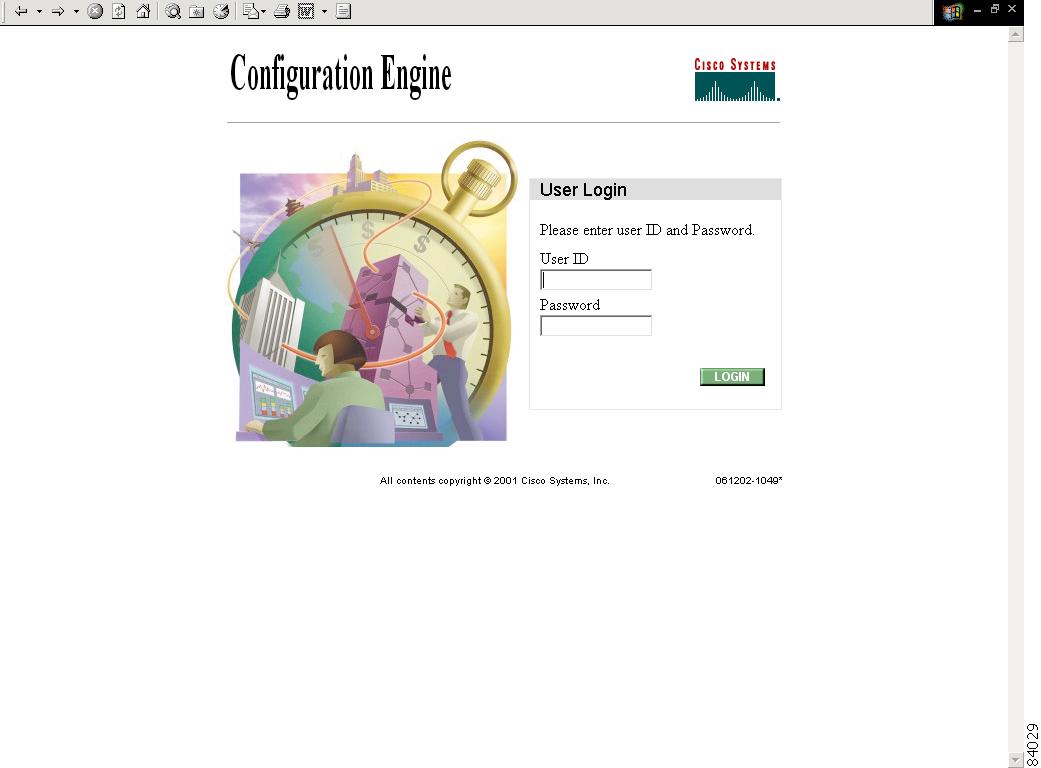
The login window appears (see Figure 3-1).
Figure 3-1 Logging In to the Configuration Server
Step 3
This is the value for the ConfigService AdminID parameter that you entered during Setup.
Step 4
Step 5
For an Administrator, the full-function Cisco CNS Configuration Engine Home page appears (see Figure 3-2).
For an Operator, a limited-function Cisco CNS Configuration Engine Home page appears where the active tabs are Home, Order Entry, and Tools (see Figure 3-3).
Figure 3-2 Administrator Home Page
Figure 3-3 Operator Home Page
How to Log Out
To log out of the system, click the Logout button.
Operator-Level Operations
After logging into the Cisco CNS Configuration Engine, an Operator has access to the following functions:
•
–
–
–
•
–
–
The order entry functions of creating a new device configuration order, editing an existing order, and managing subdevice orders are available to both Administrator and Operator.
Under tools, an Operator has access to the password editor (for changing or resetting only their own password), and the event log.
Device Configuration Order Entry
To conduct device configuration order entry operations as an Operator, follow these steps:
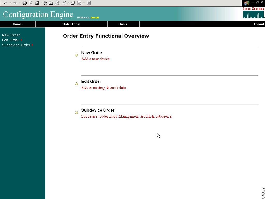
Step 1
The Order Entry page appears (see Figure 3-4).
Step 2
Figure 3-4 Order Entry for Operator-Level User
How to Change or Reset a Password at the Operator Level
To change or reset a password at the operator level, follow these steps:
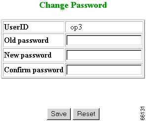
Step 1
The password editor appears (see Figure 3-5).
Figure 3-5 Operator Password Editor
Step 2
Step 3
Step 4
Step 5
Step 6
How to View the Event Log
As an operator, to view the Event Log, follow these steps:
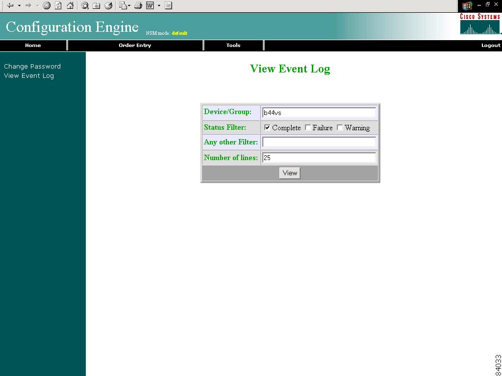
Step 1
Step 2
The Event Log control panel appears (see Figure 3-6)
Figure 3-6 Operator-Level Event Log Control Panel
Administrator-Level Operations
In Internal Directory mode, an Administrator can access all of the functions provided by the Cisco CNS Configuration Engine user interface including managing user accounts and devices.
How to Manage User Accounts
To begin managing user accounts, follow these steps:
Step 1
Step 2
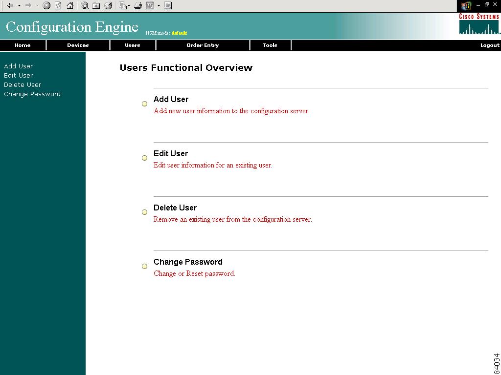
A functional overview of the user administration options appears (see Figure 3-7).
Figure 3-7 User Administration Overview
How to Add a User Account
To add a user account, follow these steps:
Step 1
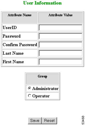
The User Information dialog box appears (see Figure 3-8).
Figure 3-8 User Information
Step 2
Step 3
Step 4
Step 5
Step 6
Step 7
Step 8
Step 9
Step 10
How to Edit a User Account
To edit a user account, follow these steps:
Step 1
A list of users appears (see Figure 3-9).
Figure 3-9 User List
Step 2
Note
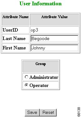
The User Information page appears (see Figure 3-10).
Figure 3-10 User Information
Step 3
Step 4
Step 5
Step 6
Step 7
Step 8
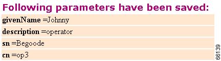
User information update status appears (see Figure 3-11).
Step 9
Figure 3-11 User Information Update Status
How to Delete a User Account
To delete a user account, follow these steps:
Step 1
Step 2
Step 3
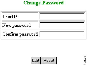
How to Change or Reset a User Password
To change or reset a user password, follow these steps:
Step 1
The Change Password dialog box (see Figure 3-12) appears.
Figure 3-12 Change Password
Step 2
Step 3
Step 4
Step 5
Step 6
Step 7
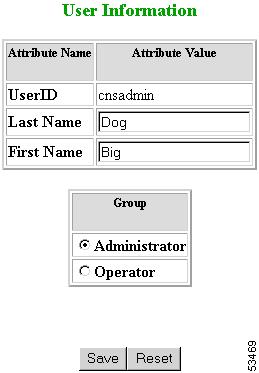
How to Change Account Privilege Level
To change the privilege level of a user account, follow these steps:
Step 1
Step 2
The User Information page appears (see Figure 3-13).
Figure 3-13 User Information
Step 3
Step 4
Step 5
Step 6
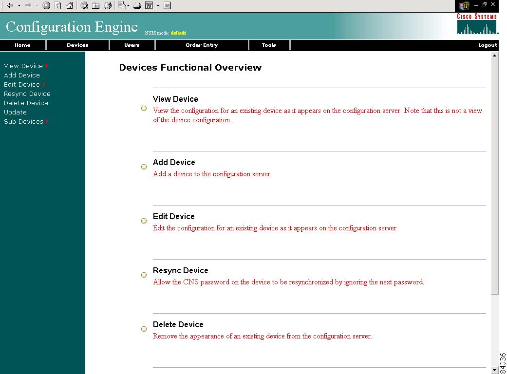
How to Manage Devices
To begin managing devices, follow these steps:
Step 1
Step 2
A functional overview of the device administration options appears (see Figure 3-14).
Figure 3-14 Device Administration Overview
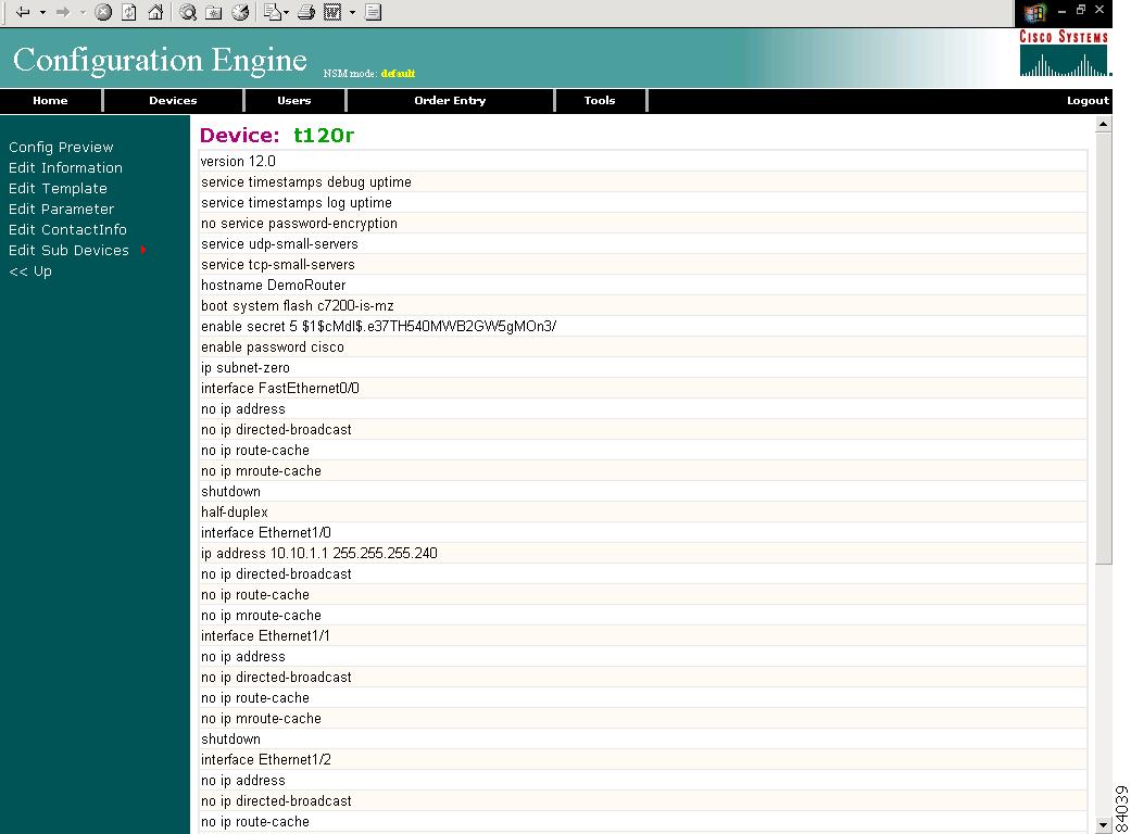
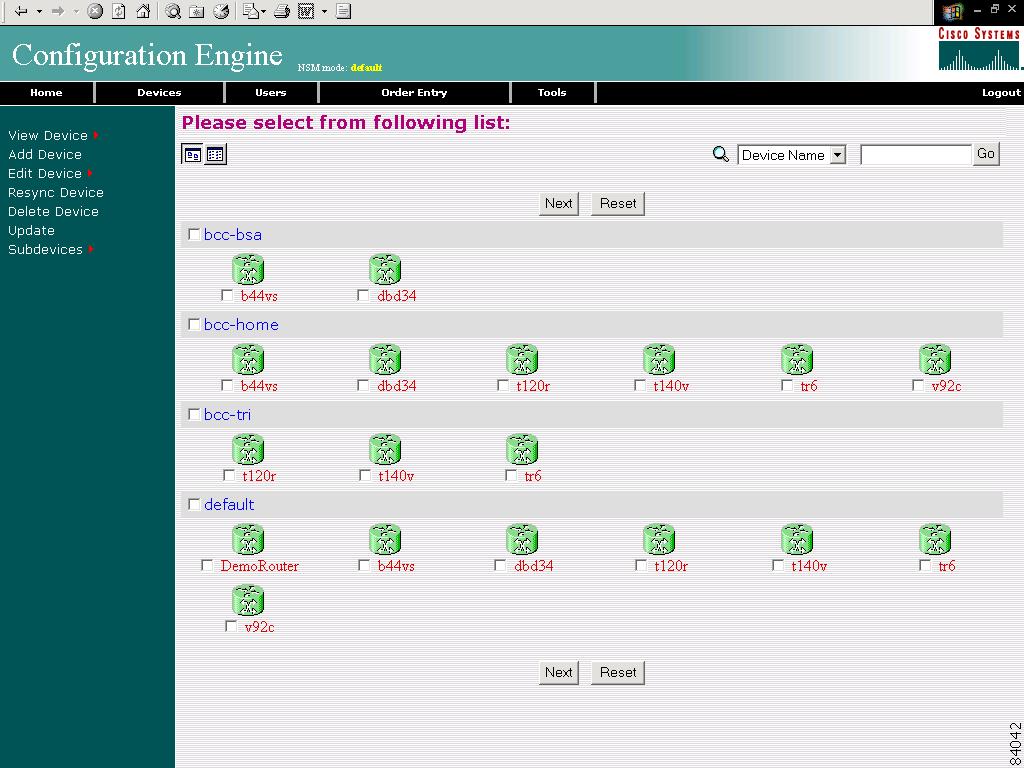
How to View Device Configuration
To view a device configuration, follow these steps:
Step 1
The Device List page appears (see Figure 3-15).
Figure 3-15 Device List
Step 2
The Configuration for that device appears.
Note
Step 3
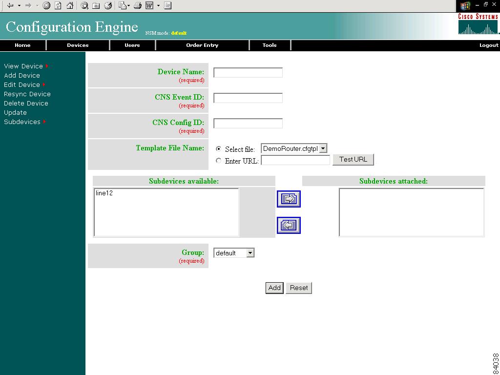
How to Add a Device
To add the logical appearance of a device to the configuration server, follow these steps:
Step 1
The Device Information page appears (see Figure 3-16).
Figure 3-16 Device Information Page
Step 2
Step 3
Step 4
The ConfigID must match the one used to manage this particular device.
Step 5
To use a template on your Cisco CNS Configuration Engine:
a.
b.
OR
To use an external template:
a.
b.
c.
If the server is unavailable or the external template cannot be accessed, an error appears. You can still save this logical device, but the template is not available until you have access to the external template.
Step 6
Step 7
Tip
Step 8
Step 9
Step 10
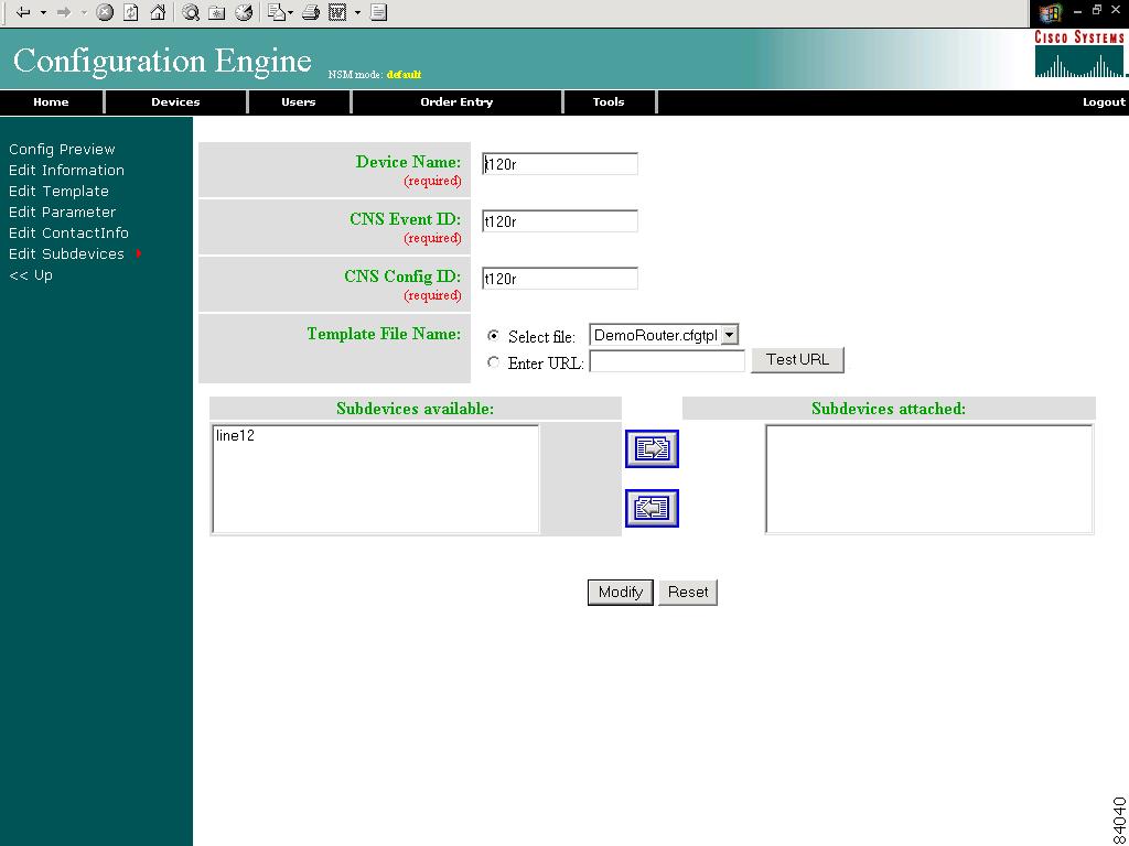
How to Edit a Device
To edit information associated with a particular device, follow these steps:
Step 1
Step 2
The device configuration appears with a menu of edit functions in the left pane (see Figure 3-17).
Figure 3-17 Device Configuration
Step 3
Step 4
Step 5
How to Edit Device Information
To edit device information, follow these steps:
Step 1
The device information dialog box appears (see Figure 3-18).
Figure 3-18 Device Information Editor
Step 2
Step 3
Step 4
Step 5
Step 6
Step 7
Step 8
Step 9
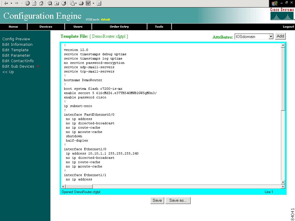
How to Edit Device Templates
To edit a device template, follow these steps:
Step 1
The template editor appears (see Figure 3-19).
Figure 3-19 Template Editor
Step 2
Step 3
Step 4
Step 5
Step 6
The default multi-line begin and end tags are ^[ and ^] respectively. The delimiter for these tags are: ~ ! @ ^ & * - = |. Do not use # or %.
A multi-line test banner might be:
banner exec ^[*This is a Test Banner1. Hi2. Hello3. Test is 1234567890*^]Step 7
Step 8
Step 9
How to Edit Device Parameters
To edit device parameters, follow these steps:
Step 1
The parameters editor appears.
Step 2
Step 3
Step 4
How to Edit Contact Information
To edit contact information related to the physical location of a device, follow these steps:
Step 1
The contact information appears.
Step 2
Step 3
Step 4
Step 5
How to Re-synchronize a Device
To re-synchronize a device, follow these steps:
Step 1
Step 2
Step 3
Step 4
How to Delete a Device
To delete the logical appearance of a device from the configuration server, follow these steps:
Step 1
Step 2
Step 3
How to Update a Device Configuration
To send an updated version of the configuration to a device, follow these steps:
Step 1
The Device Update List page appears (see Figure 3-20).
Figure 3-20 Device Update List
Step 2
Step 3
The update task dialog box appears (see Figure 3-21)
Figure 3-21 Update Task
Step 4
•
•
Step 5
Step 6
Step 7
Working with Subdevices
A subdevice is a configuration object for network modules in a modular router. When working with subdevices, it is very important to pick the correct type of interface card or module.
To work with subdevices, from the Devices Functional Overview page, click Subdevices.
The Subdevices Functional Overview page appears (see Figure 3-22).
Figure 3-22 Subdevices
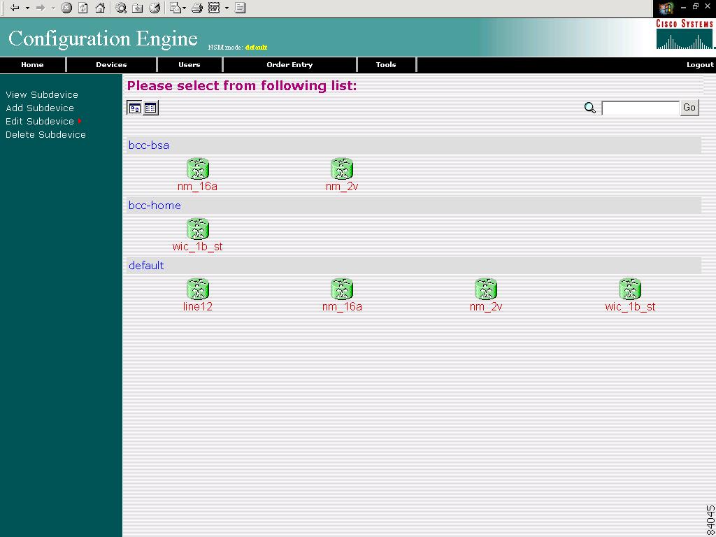
How to View Subdevices
To view subdevices, follow these steps:
Step 1
The list of subdevices appears (see Figure 3-23).
Figure 3-23 Subdevice List
Step 2
The Configuration for that device appears.
Note
Step 3
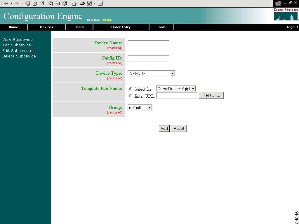
How to Add Subdevices
To add the logical appearance of a subdevice to the configuration server, follow these steps:
Step 1
The Subdevice Information page appears (see Figure 3-24).
Figure 3-24 Subdevice Information Page
Step 2
Step 3
Step 4
Device type is the name of the network module as defined in the Cisco product catalog (price list).
Step 5
To use a template on your Cisco CNS Configuration Engine:
a.
b.
OR
To use an external template:
a.
b.
c.
If the server is unavailable or the external template cannot be accessed, an error appears. You can still save this logical subdevice, but the template is not available until you have access to the external template.
Step 6
Step 7
Step 8
Step 9
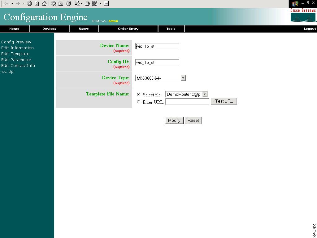
How to Edit Subdevices
To edit information associated with a particular subdevice, follow these steps:
Step 1
Step 2
The subdevice configuration appears with a menu of edit functions in the left pane (see Figure 3-25).
Figure 3-25 Subdevice Configuration
Step 3
Step 4
Step 5
How to Edit Subdevice Information
To edit subdevice information, follow these steps:
Step 1
The subdevice information editor dialog box appears (see Figure 3-26).
Figure 3-26 Device Information Editor
Step 2
Step 3
Step 4
Step 5
Step 6
Step 7
Step 8
Step 9
Step 10
How to Edit Subdevice Template
To edit a device template, follow these steps:
Step 1
The template editor appears (see Figure 3-27).
Figure 3-27 Template Editor
Step 2
Step 3
Step 4
Step 5
Step 6
The default multi-line begin and end tags are ^[ and ^] respectively. The delimiter for these tags are: ~ ! @ ^ & * - = |. Do not use # or %.
A multi-line test banner might be:
banner exec ^[*This is a Test Banner1. Hi2. Hello3. Test is 1234567890*^]Step 7
Step 8
Step 9
How to Edit Subdevice Parameters
To edit subdevice parameters, follow these steps:
Step 1
The parameters editor appears.
Step 2
Step 3
Step 4
How to Edit Contact Information
To edit contact information related to the physical location of a device, follow these steps:
Step 1
The contact information appears.
Step 2
Step 3
Step 4
Step 5
How to Delete Subdevices
To delete the logical appearance of a subdevice from the configuration server, follow these steps:
Step 1
The Subdevice Selection list appears (see Figure 3-28).
Figure 3-28 Subdevice Selection List
Step 2
Step 3
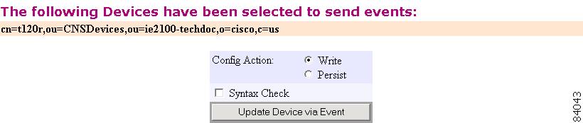
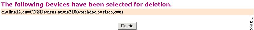
A status page appears indicating that the subdevice has been selected for deletion (see Figure 3-29).
Figure 3-29 Delete Subdevice
Step 4
Step 5
Device Configuration Order Entry
To conduct device configuration order entry tasks, from the Home page, click the Order Entry tab. The Order Entry page appears (see Figure 3-30).
Figure 3-30 Device Configuration Order Entry
How to Enter an Order for a New Device Configuration
To enter a new device configuration order, follow these steps:
Step 1
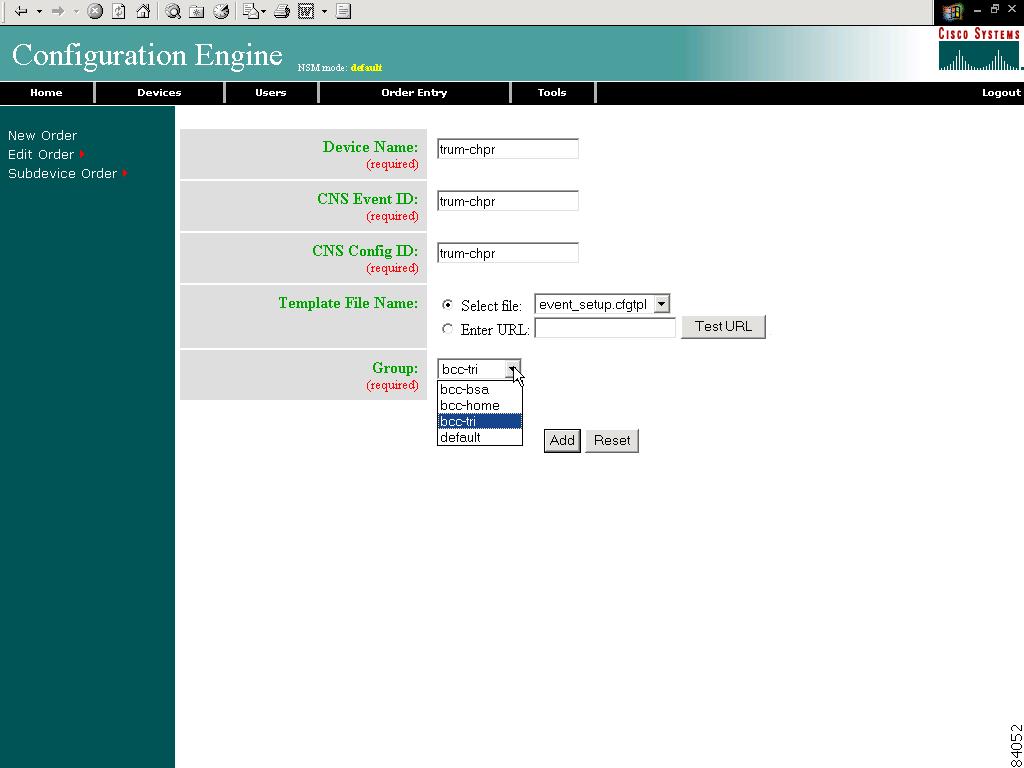
The order information dialog box appears (see Figure 3-31).
Figure 3-31 New Device Configuration Order
Step 2
Step 3
Step 4
Step 5
To use a template on your Cisco CNS Configuration Engine:
a.
b.
OR
To use an external template:
a.
b.
c.
If the server is unavailable or the external template cannot be accessed, an error appears. You can still save this logical device, but the template is not available until you have access to the external template.
Step 6
Tip
Step 7
Step 8
Step 9
Editing an Existing Configuration Order
To edit an existing configuration order, follow these steps:
Step 1
The Device List page appears (see Figure 3-15).
Step 2
The device configuration order editor appears (see Figure 3-32) with a menu of edit functions in the left pane.
Figure 3-32 Device Configuration Order Editor
How to Edit Existing Order Information
To edit existing order information, follow these steps:
Step 1
The order information dialog box appears (see Figure 3-33).
Figure 3-33 Order Information Editor
Step 2
Step 3
Step 4
Step 5
Step 6
Step 7
Step 8
Step 9
How to Edit Parameters
To edit parameter for an order, follow these steps:
Step 1
The parameter editor appears (see Figure 3-34).
Figure 3-34 Parameter Editor
Step 2
When a devices is added, the IOSDeviceID field is set to device name.
Step 3
Step 4
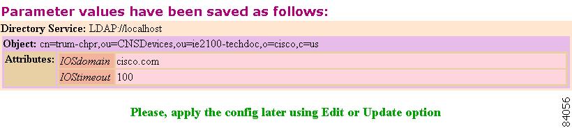
A parameter save status page appears (see Figure 3-35).
Figure 3-35 Parameter Save Status
Step 5
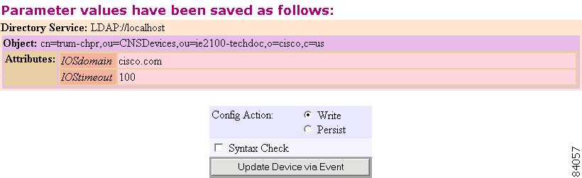
A parameter save and apply status page appears (see Figure 3-36).
Figure 3-36 Parameter Save and Apply Status
Step 6
How to Edit Contact Information
To edit contact information for an existing order, follow these steps:
Step 1
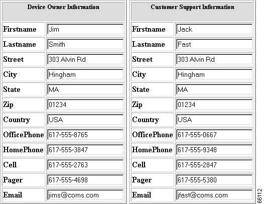
The contact information appears (see Figure 3-37).
Figure 3-37 Contact Information (Partial View)
Step 2
Step 3
Step 4
Step 5
Managing Subdevice Configuration Orders
To enter new subdevice configuration orders or edit existing ones, from the Order Entry page, click Subdevice Order. The subdevice order entry page appears (see Figure 3-38).
Figure 3-38 Subdevice Order Entry
How to Enter an Order for a New Subdevice Configuration
To enter an order for a new subdevice configuration, follow these steps:
Step 1
The subdevice information page appears (see Figure 3-24).
Step 2
Step 3
Step 4
Step 5
To use a template on your Cisco CNS Configuration Engine:
a.
b.
OR
To use an external template:
a.
b.
c.
If the server is unavailable or the external template cannot be accessed, an error appears. You can still save this logical subdevice, but the template is not available until you have access to the external template.
Step 6
Step 7
Step 8
Step 9
How to Edit an Existing Order for a Subdevice Configuration
To edit an existing order for a new subdevice configuration, follow these steps:
Step 1
Step 2
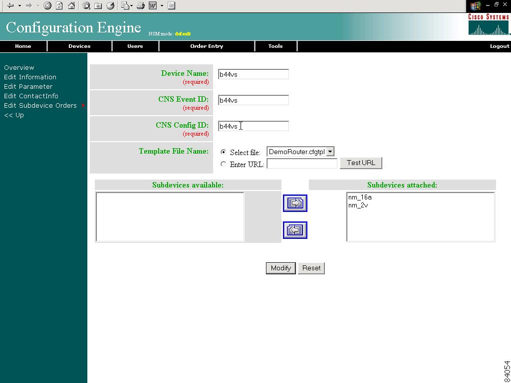
The subdevice configuration appears with a menu of edit functions in the left pane (see Figure 3-39).
Figure 3-39 Edit Subdevice Order
How to Edit Subdevice Information
To edit subdevice information, follow these steps:
Step 1
The subdevice information editor dialog box appears (see Figure 3-40).
Figure 3-40 Device Information Editor
Step 2
Step 3
Step 4
Step 5
Step 6
Step 7
Step 8
Step 9
Step 10
How to Edit Subdevice Parameters
To edit subdevice parameters, follow these steps:
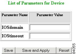
Step 1
The parameters editor appears.
Step 2
Step 3
Step 4
How to Edit Contact Information
To edit contact information related to the physical location of a device, follow these steps:
Step 1
The contact information appears.
Step 2
Step 3
Step 4
Step 5
Management Tools
To use the management tools, from the Home page, click on the Tools tab.
The Tools page appears (see Figure 3-41).
From the Tools page, you can access the following management tools:
•
•
•
•
Figure 3-41 Management Tools
How to Use DAT
To connect to the user interface for the Directory Administration Tool (DAT), follow these steps:
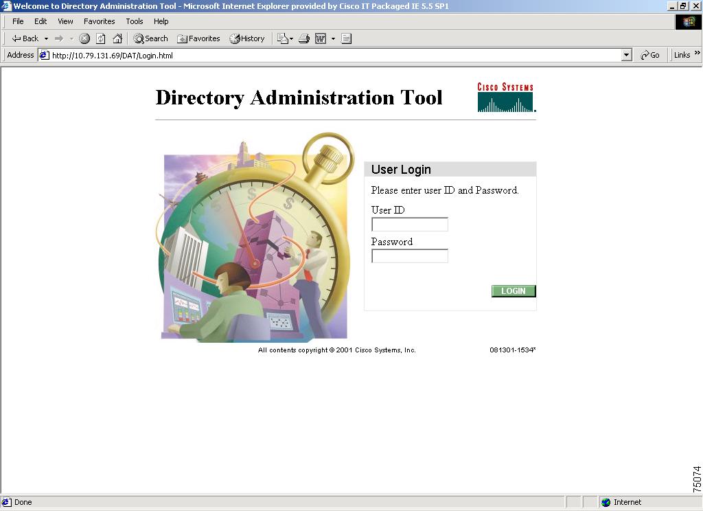
Step 1
The login window appears (see Figure 3-42).
Figure 3-42 Directory Administration Tool Login Window
Step 2
This is the LDAP proxy user name for the Cisco CNS Configuration Engine administrative account that you entered during Setup.
Step 3
Step 4
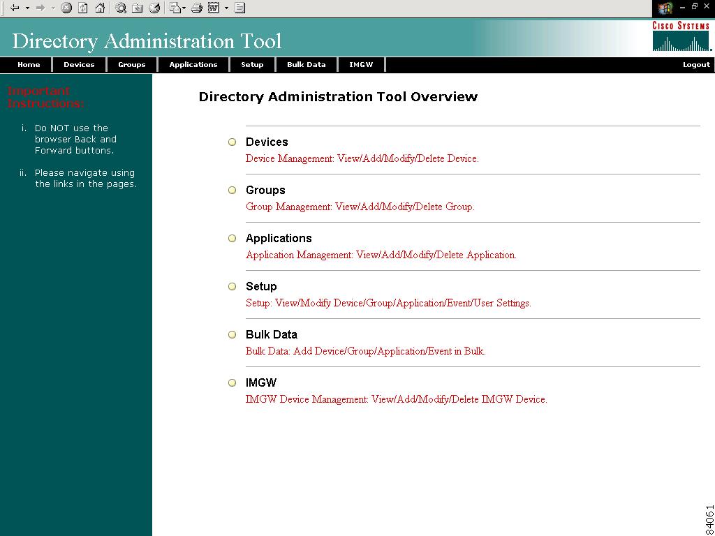
The Directory Administration Tool Overview page appears (see Figure 3-43).
Figure 3-43 DAT Home Page
Step 5
Managing Data
The data manager tools allows you to:
•
•
How to Schedule Data Backup
To schedule a data backup, follow these steps:
Step 1
The Data Manager page appears (see Figure 3-44).
Figure 3-44 Data Manager
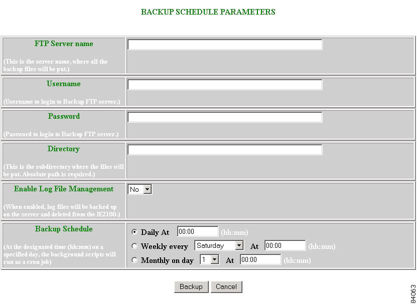
Step 2
The backup information dialog box appears (see Figure 3-45).
Figure 3-45 Backup Schedule Parameters
Step 3
Step 4
Step 5
Step 6
Step 7
Step 8
Note
Step 9
Step 10
Step 11
For more information about backup and restore, see "Backup and Restore" section.
How to View Log Files
To view various log files, follow these steps:
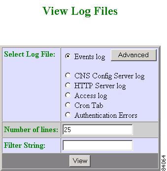
Step 1
The View Log Files dialog box appears (see Figure 3-46).
Figure 3-46 Log File Viewer
Step 2
Step 3
Step 4
Step 5
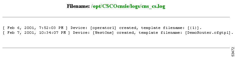
A report displays (for an example see Figure 3-47).
Step 6
Figure 3-47 Log File
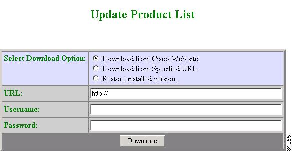
How to Update Product List
The product list is a mapping between product name of the network modules as specified in the pricing list and the numeric identification number stored in EPROM. As new products are added, this list grows and hence the need for the Cisco CNS Configuration Engine to update this list whenever new products are added. This list can be downloaded from the Cisco web site at: http://www.cisco.com.
To update the product list, follow these steps:
Step 1
The Update Product List dialog box appears (see Figure 3-48).
Figure 3-48 Update Product List
Step 2
Step 3
Step 4
Step 5
Step 6
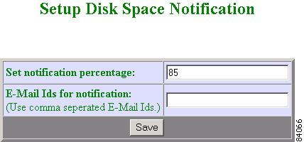
How to Manage Disk Space
To setup disk space e-mail notification of disk space usage, follow these steps:
Step 1
The Setup Disk Space Notification dialog box appears (see Figure 3-49).
Figure 3-49 Disk Space Notification
Step 2
Step 3
Step 4
Step 5
How to Manage Directory Content
With the directory manager you can:
•
•
•
•
To use the directory manager tool, click Directory Mgr.
The Directory Manager page appears (see Figure 3-50).
Figure 3-50 Directory Manager
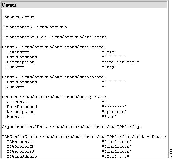
How to View the Directory Information Tree
To view the directory information tree (DIT), click View DIT. The DIT appears (see Figure 3-51).
Figure 3-51 DIT (Partial View)
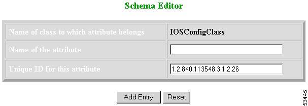
How to Edit the Schema
To edit the schema, follow these steps:
Step 1
The schema editor appears (see Figure 3-52).
Figure 3-52 Schema Editor
Step 2
Step 3
Step 4
Step 5
Step 6
How to Undo Schema Edit
You can undo the last schema update and revert to the previous schema by clicking Undo Edit on the Directory Manager page.
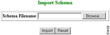
How to Import Schema
You can import a schema accessible from your computer. However, the file must be in XML format and conform to the definitions specified in the document type definition (DTD) file shown here:
<!-- DTD for DAML --><!-- Last updated: 2000-10-03 --><!ELEMENT daml (schema)><!-- SCHEMA --><!ELEMENT schema (class+,attribute-type+,link*)><!-- element types common to class and attribute-type --><!ELEMENT class (auxclass*,attribute+)><!ATTLIST classname (#PCDATA) #REQUIREDid ID #IMPLIEDsuperior IDREF #IMPLIEDtype (structural|abstract|auxiliary) #REQUIREDdescription? #IMPLIED><!ELEMENT auxclass EMPTY><!ATTLIST auxclassref IDREF #REQUIRED><!ELEMENT attribute EMPTY><!ATTLIST attributeref IDREF #REQUIREDrequired (true|false) #REQUIRED><!ELEMENT attribute-type EMPTY><!ATTLIST attribute-typename (#PCDATA) #REQUIREDid ID #REQUIREDsingle-value (true|false) "false"syntax (string|integer|boolean|binary|key) "string"><!ELEMENT link EMPTY><!ATTLIST linkfromclass IDREF #REQUIREDfromattr IDREF #REQUIREDtoclass IDREF #REQUIREDtoattr IDREF #REQUIRED>For example, a valid schema would look like:
<?xml version="1.0" encoding="UTF-8"?><!DOCTYPE dsml SYSTEM "dsml.dtd"><dsml complete="true"><directory-schema><attribute-type id="IOSe1ipaddress" single-value="true" obsolete="false" user-modification="true"><name>IOSe1ipaddress</name><object-identifier>1.2.840.113548.3.1.2.20</object-identifier><syntax>string</syntax></attribute-type><class id="IOSConfigClass" superior="top" type="structural" obsolete="false"><name>IOSConfigClass</name><object-identifier>1.2.840.113548.3.2.2.1</object-identifier><attribute ref="1.2.840.113548.3.1.2.20" required="false"/></class></directory-schema></dsml>To import a schema from an XML file accessible from your computer, follow these steps:
Step 1
The import schema dialog box appears (see Figure 3-53).
Figure 3-53 Import Schema
Step 2
Use the browse function to locate the file, if needed.
Step 3
Step 4
Step 5
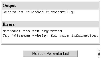
How to Reload the Schema
To reload the schema, follow these steps:
Step 1
The reload operation runs and a report displays (see Figure 3-54).
Figure 3-54 Reload Schema
Step 2
Step 3
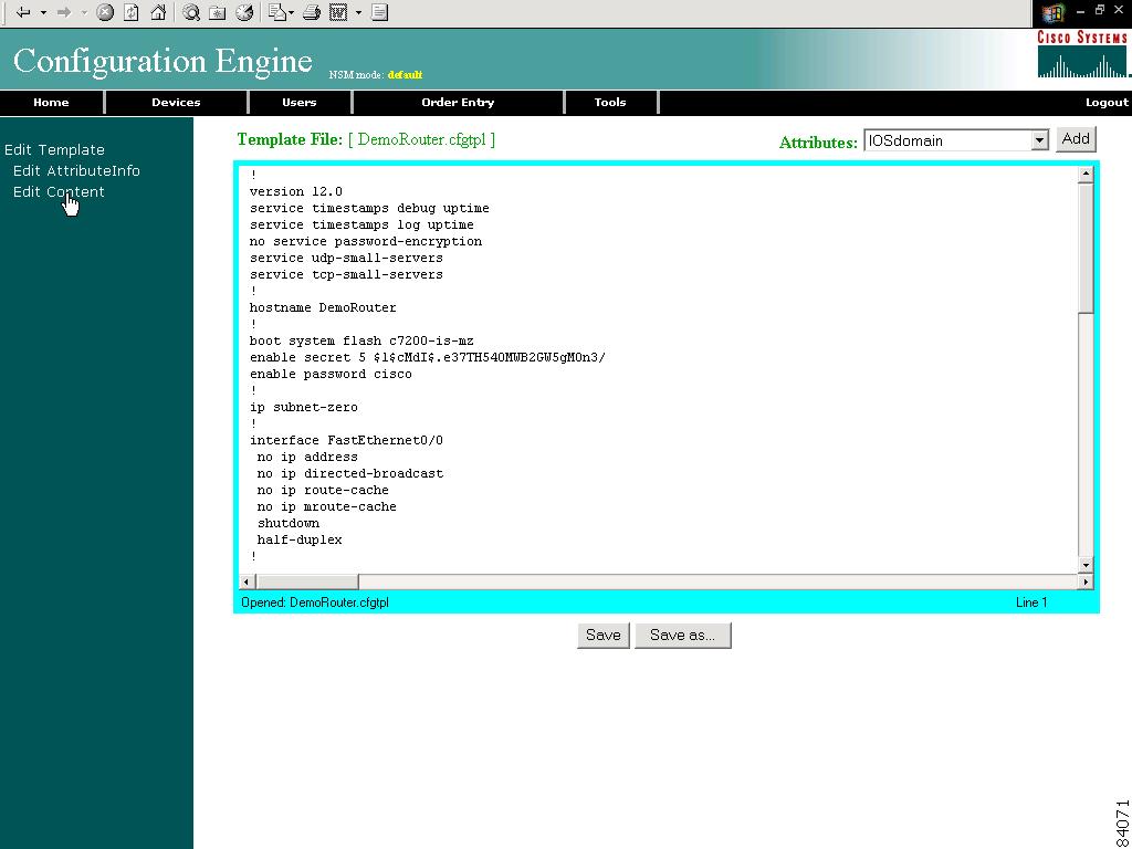
Templates and Template Management
When creating a template, it is possible to specify variables that will be contextually substituted. Many of these variables are available in the drop-down menu in the Template Editor (see Figure 3-58). It is also possible to create these files offline without the Template Editor and still use these variables.
The basic format of a template file is simply the text of the configuration to be downloaded to your device (see "Sample Template" section). However, you can put variable substitutions of the following form (for example, the variable name could be iosipaddress):
Internal directory mode:${LDAP://this:attrName=iosipaddress}External directory mode:${LDAP://10.1.2.3/cn=Device1,ou=CNSDevices,o=cisco,c=us:attrName=iosipaddress}It is possible to create segments of templates that can be included in other templates. For example, you might have an Ethernet configuration that would be used by multiple devices. In each device template, you could have:
#include /opt/CSCOcnsie/Templates/ethernet_setup.cfgtplNow, you could centralize all the administration for Ethernet configuration in one file.
Caution
Sample Template
The following sample is the configuration template for the DemoRouter (DemoRouter.cfgtpl), which is pre-loaded on your system:
!version 12.0service timestamps debug uptimeservice timestamps log uptimeno service password-encryptionservice udp-small-serversservice tcp-small-servers!hostname DemoRouter!boot system flash c7200-is-mzenable secret 5 $1$cMdI$.e37TH540MWB2GW5gMOn3/enable password cisco!ip subnet-zero!interface FastEthernet0/0no ip addressno ip directed-broadcastno ip route-cacheno ip mroute-cacheshutdownhalf-duplex!interface Ethernet1/0ip address 10.10.1.1 255.255.255.240no ip directed-broadcastno ip route-cacheno ip mroute-cache!interface Ethernet1/1no ip addressno ip directed-broadcastno ip route-cacheno ip mroute-cacheshutdown!interface Ethernet1/2no ip addressno ip directed-broadcastno ip route-cacheno ip mroute-cacheshutdown!interface Ethernet1/3no ip addressno ip directed-broadcastno ip route-cacheno ip mroute-cacheshutdown!ip classlessip route 0.0.0.0 0.0.0.0 10.10.1.1ip http server!dialer-list 1 protocol ip permitdialer-list 1 protocol ipx permit!line con 0transport input noneline aux 0line vty 0 4password ciscologin!endTemplates for Modular Routers
The template mechanism for the devices has been enhanced to support modular routers. A modular router chassis includes slots in which you can install modules. You can install any module into any available slot in the chassis. Some modules like 2 Ethernet 2 WAN card slot module can in turn have sub slots to install interface cards or line cards. Device management has been extended to support subdevices representing line cards.
Additional attributes representing line card number, line card type, and subdevices have been added to the existing device object structure in the directory server in order to have the same structure to represent the main device or the subdevice.
Currently, card type is a string that maps to the product code of the network module. Since the EPROM data in the card stores part numbers only, not product codes, the part numbers are mapped to product codes. The user uses part numbers and the configuration server maps part number to product codes.
In the context of main device, the line card number and line card type fields make no sense and hence are set to NULL value. The subdevices field in the sub device (representing the line card) is set to NULL value.
New interface variable support has been added. These variables are included in the templates, which are parameterize with the interface numbers in the template. These are not attributes. They are special format variables that are replaced by the configuration server based on the interface information, which comes from the device. These variables only specify the relative position of the interface on the module and are replaced by the actual slot number, shelf-ID or port number. The interface variables are wrapped in percent sign (%) characters and specify the type, if any, and the relative position. The configuration server replaces these variables with the interface numbers. The interface type still has to be specified in the CLI using the following syntax:
Interface Variable = %[InterfaceType] RelativePosition%
For example:
%FastEthernet 0% for interface FastEthernet
%Serial 0% interface Serial
%T1 0% controller T1
%E1 0% controller E1
%voice-port 0% voice-port
Example 1:
A network module with two FastEthernet ports plugged in Slot 2 would be referred in the configuration CLI as FastEthernet 2/0 and FastEthernet 2/1 and referred in the template as FastEthernet %FastEthernet 0% and FastEthernet %FastEthernet 1%:
!interface FatsEthernet 2/0ip address 10.10.1.1 255.255.255.0!interface FatsEthernet 2/1ip address 20.20.1.1 255.255.255.0!Templates for these CLIs would be:
!interface FastEthernet %FastEthernet 0%ip address 10.10.1.1 255.255.255.0!interface FastEthernet %FastEthernet 1%ip address 20.20.1.1 255.255.255.0!Example 2 (Voice card with two ports plugged in slot 3):
!voice-port 3/0/0description 4082224444!voice-port 3/0/0description 4082225555!Templates for these CLIs would be:
!voice-port %voice-port 0%description 4082224444!voice-port %voice-port 1%description 4082225555!The main device template does not include links to the subdevice templates. The subdevice templates are appended to the main device template. The line card number are a parameter in the subdevice templates.
All the CLI commands which reference a line card interface are specified in the subdevice template for that line card. This implies that any command in the global configuration mode, or otherwise, that refers to a particular line card interface is in the template for that subdevice (line card) and not in the main device template.
Only the CLI commands in the global configuration mode, and not pertaining to the any specific interface, are specified in the main device template.
The port number and channel number are not be template parameters since these are fixed for a given line card. The network administrator can configure specific channels on the interfaces by explicitly specifying the channels in the subdevice templates.
For example:
interface Serial %Serial 0%:0
Sample Templates for Modular Router
The names of the attributes for slot, slot-unit, line card type and so forth, are used for demonstration purposes.
Main Device Template
!version 12.2no parser cacheno service single-slot-reload-enableservice timestamps debug uptimeservice timestamps log uptimeno service password-encryption!hostname 2600!logging rate-limit console 10 except errors!memory-size iomem 25ip subnet-zero!!!no ip dhcp-client network-discoverylcp max-session-starts 0!ip classlessno ip http server!call rsvp-sync!no mgcp timer receive-rtcp!mgcp profile default!dial-peer cor custom!!!!line con 0line aux 0line vty 0 4loginline vty 5 15login!Fastethernet Template
Interface FastEthernet %FastEthernet 0%ip address 10.0.0.1 255.0.0.0shutdownspeed autoVoice-port Template
voice-port %voice-port 0%playout-delay mode adaptive!voice-port %voice-port 1%!dial-peer voice 10 potsdestination-pattern 200port %voice-port 0%forward-digits allvoice-port %voice-port 0%!dial-peer voice 20 potsdestination-pattern 100port %voice-port 0%!voice-port %voice-port 1%Modular Router Events
Modular router events are published to the event bus and are accessible to applications connected to the bus. The IOS device publishes the system hardware configuration in the cisco.cns.config.device-details event after hardware discovery. The Cisco CNS Configuration Engine is configured to listen for this event, retrieve it and extract the hardware configuration of the device.
Following is the DTD of the cisco.cns.config.device-details event that the Cisco IOS device sends:
<!ELEMENT device-details (config-id, connect-interface?, card-info*><!ELEMENT config-id (#PCDATA)><!ELEMENT connect-interface (#PCDATA)><!ELEMENT card-info (card-info+)><!ELEMENT card-info (card-type,card-desc?,slot,daughter?,serial-number,part-number,hw-version?,board-revision? ,ports?,controller?,rma-number?,test-history?,eeprom-version?,eeprom-data?,interface?,cont roller?,voice-port?)><!ELEMENT card-type (#PCDATA)><!ELEMENT card-desc (#PCDATA)><!ELEMENT slot (#PCDATA)><!ELEMENT daughter (#PCDATA)><!ELEMENT serial-number (#PCDATA)><!ELEMENT part-number (#PCDATA)><!ELEMENT hw-version (#PCDATA)><!ELEMENT board-revision (#PCDATA)><!ELEMENT ports (#PCDATA)><!ELEMENT controller (#PCDATA)><!ELEMENT rma-number (#PCDATA)><!ELEMENT test-history (#PCDATA)><!ELEMENT eeprom-version (#PCDATA)><!ELEMENT eeprom-data (#PCDATA)><!ELEMENT interface (#PCDATA)><!ELEMENT controller (#PCDATA)><!ELEMENT voice-port (#PCDATA)>Dynamic Templates
There may be times when the actual contents of a template needs to be dynamically generated. To do this, you would use the #call mechanism. This executes a JavaScript program whose output becomes part of the template. The program is re-executed each time a device asks for the template.
For example, you might want to distribute the load across the various event gateway processes without permanently assigning a device to a particular event gateway. This is useful because of the limit of 500 devices per event gateway daemon instance.
Let us take the following template as an example:
version 12.0service timestamps debug uptimeservice timestamps log uptimeno service password-encryptionservice udp-small-serversservice tcp-small-servers!hostname DemoRouter#call /opt/CSCOcnsie/Templates/event_setup.jsHere is an example of an event_setup.js that one might use:
/** An instance of Event Gateway resides on every odd port from 11011 to 11031.* This will choose a random one in this range so that devices are spread out* evenly among the various ports. Adjust the IP address in the println* statement to be the address of the IE2100 itself.*/var port = Math.floor(Math.random() * 11) * 2 + 11011;println("cns event 10.1.6.131 " + port.toString());The result of this combination would be a template that appears as follows:
version 12.0service timestamps debug uptimeservice timestamps log uptimeno service password-encryptionservice udp-small-serversservice tcp-small-servers!hostname DemoRoutercns event 10.1.6.131 11017The last line is programmatically determined and recalculated every time the template is requested by the device. So the next time a device requests this template, the last line might be:
cns event 10.1.6.131 11023Simple modifications to event_setup.js could even be used to distribute devices across multiple CNS 2100 Series devices (by dynamically generating the IP address). It could also be used to affect any part of the device configuration—be it DNS servers or routing tables. Anything that is printed out by the JavaScript program becomes a dynamic part of the template.
Control Structures
The configuration template can include simple control structures such as, if, else and elseif. By using these control structures, the user can include or exclude a block of CLI commands based on a parameter stored in the directory.
The syntax for these # preprocessing control structures is as follows:
Syntax Description
#if <URL> = constant
cli-command(s)
#elseif <URL> = constant
cli-command(s)
#else
cli-command(s)
#endif
Where constant is an integer, boolean or a string in single quotes and the <URL> is a URL pointing to an attribute in the Directory or Database.
Note
Usage Guidelines
The configuration template can include #define entries to define short names for long URLs.
The syntax for the #define preprocessing command is as follows
#define definition-name <URL> | constant
where <URL> is a reference to an attribute in the directory.
The configuration template can contain another # preprocessing command #include, which allows the inclusion of other configuration templates or the results of an ASP page.
The syntax for the # preprocessing command is as follows:
#include <URL> | `<Filename>' | <Filename>
Whenever an #include directive is encountered, it is replaced by the content of the file.
The following configuration template sample includes either IP sub-template or ISDN sub-template based on the value of the parameter protocol in the directory or database.
Examples
!version 12.0service timestamps debug uptimeservice timestamps log uptimeno service password-encryptionservice udp-small-serversservice tcp-small-servers!hostname ${LDAP://this:attrName=IOShostname}#if ${LDAP://this:attrName=IOSIPprotocol} = true then#include ${LDAP://this:attrName=IPsubTemplate}#else#include ${LDAP://this:attrName=ISDNsubTemplate}#endifThe parameter, ${LDAP://this:attrName=IPsubTemplate} contains the location of the file.
How to Manage Templates
To use the template manager tool, click Template Mgr.
The Template Manager page appears (see Figure 3-55).
Figure 3-55 Template Manager
How to Add a Template
To add a template to the directory, follow these steps:
Step 1
A blank template page appears.
Step 2
Step 3
Step 4
Step 5
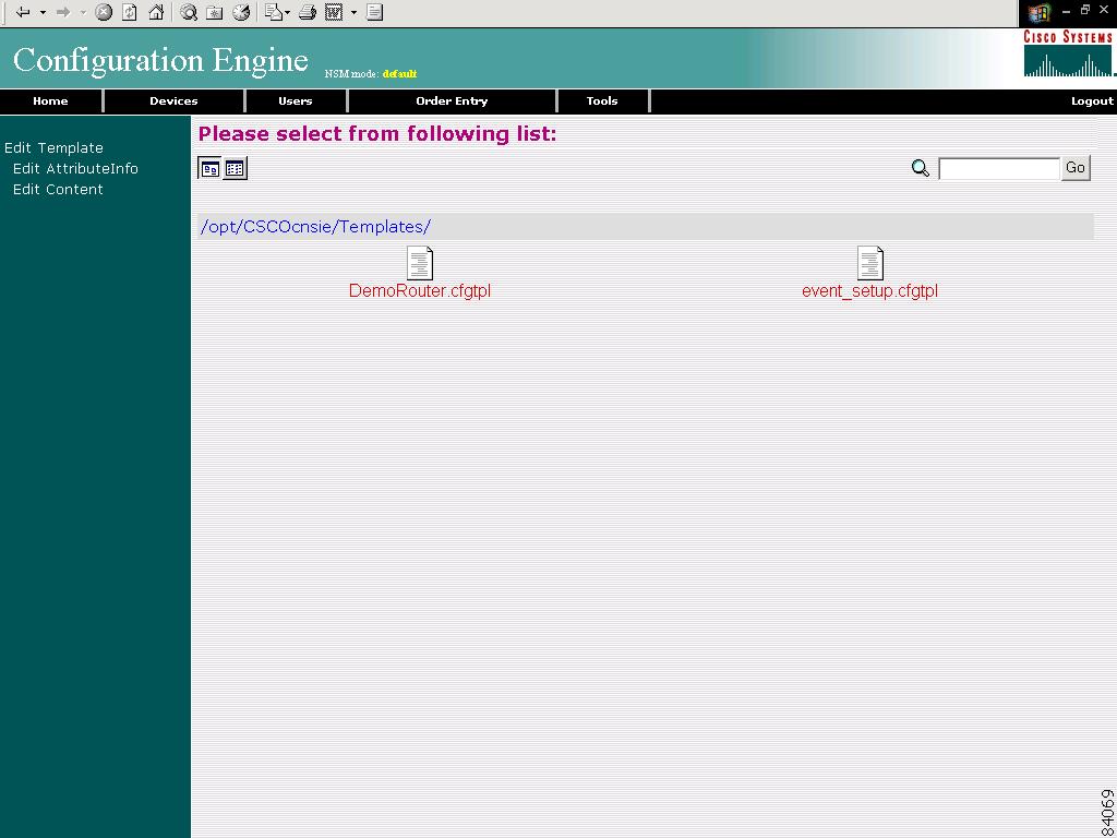
How to Edit a Template
To edit parameters (attribute information) and the content of a template, follow these steps:
Step 1
The Template list appears (see Figure 3-56).
Figure 3-56 Template List
Step 2
The template file appears.
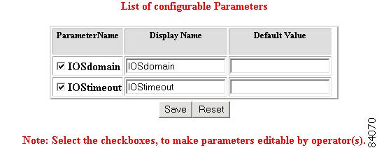
Step 3
a.
The list of configurable parameters appears (see Figure 3-57).
Figure 3-57 Parameter Editor
b.
Only selected (see check box) parameters appear in Order Entry.
The Display Name and Default Value appear when an operator edits parameters by means of Order Entry.
c.
d.
e.
Step 4
a.
The template content appears (see Figure 3-58).
Figure 3-58 Template Content
b.
c.
d.
e.
How to Delete a Template
To delete a template, follow these steps:
Step 1
The template file list appears (see Figure 3-56).
Step 2
Step 3
Step 4
How to Import a Template
To import a template file to the configuration server from another location, follow these steps:
Step 1
Step 2
Step 3
Step 4
Step 5
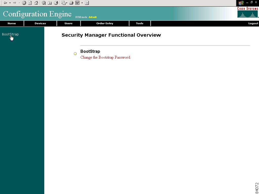
Security Manager
With the security manager tool you can change the bootstap password.
The bootstrap password is used to authenticate a Cisco IOS device before it connects to the Event Gateway. For additional information see "Authentication settings" section)
To use the security manager tool, from the Tools page, click Security Mgr.
The Security Manager page appears (see Figure 3-59).
Figure 3-59 Security Manager
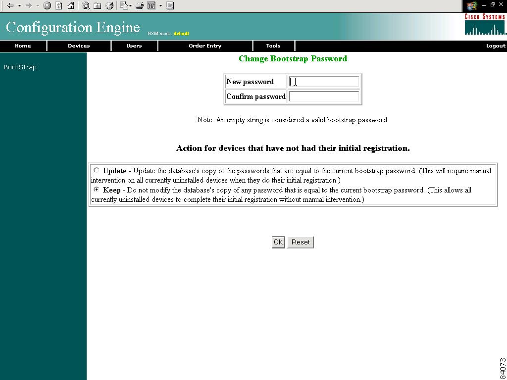
How to Change Bootstrap Password
To change the bootstrap password, follow these steps:
Step 1
The Change Bootstrap Password page appears (see Figure 3-60).
Figure 3-60 Change Bootstrap Password
Step 2
Step 3
Step 4
Step 5
Step 6
Step 7
Backup and Restore
This section explains how to backup and recover your directory store, templates, and certain configuration files.
Backup
The backup function is a script that takes the values you enter in the dialog box for scheduling backups under the Directory Manager (Tools > Directory Mgr. > ScheduleBackup) in the Configuration Registrar (see "How to Schedule Data Backup" section).
How the Backup Works
The backup sequence is as follows:
1.
When the script backs up CNS Directory Service, it sets the directory in an inactive state until the backup completes.
2.
The script stores the database file in the /extra partition of the CNS 2100 Series system drive. All other files (templates, http.conf, jserv.properties, and so on) are saved as tar [tape archive] files, then zipped with the CNS Directory Service backup.
3.
4.
The /extra/old directory contains only one previous backup. Each backup operation overwrites this space with the new backup data.
Restore
To restore CNS Directory Service, template, and other configuration files to the CNS 2100 Series system, complete the following steps:
Step 1
For example, use the console interface to ping a known device on the network, such as the file server that has the backup file.
Step 2
Step 3
The backup file is in a zip format.
Step 4
zcat <filename>.gz | tar xvf -
where <filename> consists of a date/time notation. For example, backup<date_and_timestamp_of_backup>
How to Restore the CNS Directory
To restore the CNS directory, complete these steps:
Step 1
su - dcdadmin -c /opt/CSCOcnsie/scripts/dclschemaload.txt
This command will fail if the CNS directory server is not running.
Step 2
su - dcdadmin -c dcdstop
(If the command fails, try running: /etc/rc.d/init.d/NetAppDCL stop)
Step 3
su - dcdadmin -c "dcbckdib /y restore /extra"
Step 4
su - dcdadmin -c dcdstart
Step 5
/etc/rc.d/init.d/httpd restart
/etc/rc.d/init.d/Imgw restart