Feedback Feedback
|
Table Of Contents
Installation and Configuration for Common Criteria EAL4 Evaluated Cisco IOS/Firewall
Supported Hardware and Software Versions
Security Implementation Considerations
Remote Administration and Management
Verification of Image and Hardware
Disabling H.323 and Session Initiation Protocol (SIP)
Setting the Default Access Control List (ACL) / Firewall Policy
Enabling Remote and Local AAA services
Configuring Firewall Fail Close Functionality
MD5 Hash Values for Cisco IOS Software Images
Obtaining Technical Assistance
Appendix A.1: Cisco 1841 Series Modules
Appendix A.2: Cisco 2800 Series Module
Appendix A.3: Cisco 3800 Series Module
Appendix A.4: Cisco 7000 Series Module Support
Appendix B: PIX Firewall Syslog Server (PFSS) Guidance
I. Release Notes for PIX Firewall Syslog Server 5.1(2)
II. Release Notes for PIX Firewall Syslog Server 5.1(1)
Appendix C: RSA Token Implementation Guidance
Installation and Configuration for Common Criteria EAL4 Evaluated Cisco IOS/Firewall
October 2006—Version 1.0Contents
This document describes how to install and configure Cisco IOS routers in accordance with the Common Criteria Evaluation Assurance Level 4 (EAL4) evaluated Cisco IOS/Firewall.
Note
Any changes to the information provided in this document will result in the Cisco IOS router not being compliant with Cisco IOS/Firewall as evaluated and may make it insecure.
This document includes the following sections:
•
•
•
•
This document also includes the following appendices:
•
•
•
•
•
•
Introduction
This document is an addendum to the Cisco IOS Release 12.3/12.3T and 12.4/12.4T documentation sets. It should be read before configuring a Cisco IOS router in accordance with the Common Criteria Evaluation Assurance Level 4 (EAL4) evaluated Cisco IOS/Firewall. This document contains instruction on a variety of security configuration issues and all of the instruction contained within should be followed, unless otherwise stated, when installing or configuring a Cisco IOS router in accordance with the Common Criteria evaluated configuration.
Cisco product documentation includes:
•
•
•
The following Cisco IOS Release documentation is referenced by this document:
•
•
•
•
•
•
•
•
•
•
•
•
•
•
•
Cisco IOS documentation is available on CD-ROM, in printed-paper form, and online (in both HTML and PDF formats). This document should be used in conjunction with the Cisco IOS/Firewall Common Criteria Evaluation Documentation CD-ROM. The Cisco IOS documents listed above can be found on the CD-ROM or on the Internet at: http://www.cisco.com/univercd/cc/td/doc/product/software/ios123/index.htm
The Cisco IOS Firewall Target of Evaluation relies on a Windows 2000 computer to act as an audit server. Windows 2000 is configured in it's EAL 4 evaluated configuration to support this TOE. Microsoft Windows 2000 Evaluated Configuration documentation can be found at the following links:
Windows 2000 Common Criteria Evaluated Configuration User's Guide: http://www.microsoft.com/technet/security/prodtech/Windows2000/w2kccug/default.mspx
Windows 2000 Common Criteria Evaluated Configuration Administrator's Guide: http://www.microsoft.com/technet/security/prodtech/windows2000/w2kccadm/default.mspx
Windows 2000 Common Criteria Security Configuration Guide: http://www.microsoft.com/technet/security/prodtech/windows2000/w2kccscg/default.mspx
Audience
This document is written for administrators configuring a Cisco IOS router in accordance with the Common Criteria evaluated Cisco IOS/Firewall. This document assumes you are familiar with networks and network terminology, that you are a trusted individual, and that you have been trained in the use of firewalls and their application. There are no configurable components of the Cisco router that are accessible to non-administrative users (end-users), and hence there is no user-level documentation.
Supported Hardware and Software Versions
Only the following combinations of hardware and software in Table 1 are compliant with Common Criteria evaluated Cisco IOS/Firewall. The Common Criteria evaluated Cisco IOS/Firewall configuration also includes the PIX Firewall Syslog Server version 5.1(3). This software has been included to perform viewing, searching and sorting of audit data.
Security Information
In addition to the regulatory compliance documentation for each hardware platform listed in Table 2, the sections that follow provide additional security information for use with a Common Criteria evaluated Cisco IOS/Firewall router.
Security Implementation Considerations
The sections that follow provide implementation considerations that need to be addressed to administer Cisco IOS Routers in a secure manner consistent with Common Criteria evaluated Cisco IOS/Firewall.
The TOE must not be connected to any untrusted network prior reading this section and following the secure installation and generation procedures contained within this document in their entirety and confirming that all TOE components (including PFSS) are functional.
The administrator of the evaluated product is warned to pay careful attention to the following potential insecure configurations.
Modes of Operation
Cisco IOS Routers
A Cisco IOS router has several modes of operation, these modes are as follows:
Booting—while booting, the routers drop all network traffic until the router image and configuration has loaded. This mode of operation automatically progresses to the Normal mode of operation. During booting, a user may press the break key on a console connection within the first 60 seconds of startup to enter the ROM Monitor mode of operation. This Booting mode is referred to in the Cisco IOS guidance documentation as "ROM Monitor Initialization." Additionally if the Router does not find a valid operating system image it will enter ROM Monitor mode and not normal mode therefore protecting the router from booting into an insecure state.
Normal—The Cisco IOS router image and configuration is loaded and the router is operating as configured. It should be noted that all levels of administrative access occur in this mode and that all router based TOE security functions are operating. While operating the TOE has little interaction with the administrator. However, the configuration of the TOE can have a detrimental effect on security. Misconfiguration of the TOE could result in the unprotected network having access to the internal/protected network
ROM Monitor—This mode of operation is a maintenance, debugging and disaster recovery mode. While the router is in this mode, no network traffic is routed between the network interfaces. In this state the router may be configured to upload a new boot image from a specified TFTP server, perform configuration tasks and run various debugging commands. It should be noted that while no administrator password is required to enter ROM monitor mode, physical access to the router is required, therefore the router should be stored in a physically secure location to avoid unauthorized access which may lead to the router being placed in an insecure state.
Following operational error the router reboots (once power supply is available) and enters booting mode.
The router includes facilities to guard against failure caused by the PIX Firewall Syslog Server (PFSS) not being available. This safeguard includes the use of the TCP Syslog protocol to ensure that audit events are reliably delivered to the PFSS. The TCP Syslog option should be configured on the router using the logging host ip-address tcp port-number command as show in Configuring Firewall Fail Close Functionality section of the user guidance. With TCP logging configured, new sessions through the router will eventually be disallowed if log messages cannot be forward to the PFSS within approximately a nine minute period.
PIX Firewall Syslog Server
The PIX Firewall Syslog Server (PFSS) has several modes of operation:
PFSS Service Started—the PFSS service has been started and is listening on the specified port for TCP Syslog traffic. TCP Syslog traffic received will be entered into log files on the PFSS hosts hard drive, logging will continue until interrupted or the hosts hard disk reaches the specified "% disk full" threshold (default is 90%). Once the service has started, all configured events will be logged allowing an administrator to detect any unauthorized events.
PFSS Service Stopped—The PFSS service may be in a stopped state as a result of not being started by the host OS after reboot, having been stopped by the host OS due to error, or have stopped itself after detecting that the host hard drive is full. Once the service has been stopped logging of system events will not occur which may result in unauthorized event going undetected, however if the router is continually unable to connect to the syslog server for a TCP retry period of nine minutes the router will fail close, disallowing all new connection attempts with the exception of connections to the administration interface. The router will remain in this state until the connection to the PFSS is made available and TCP Syslog configuration is re-established.
PFSS Viewer Running—The PFSS Viewer application is running, allowing authorized administrators to perform the required searching and sorting operations whilst viewing the log files. The viewer is a simple application that is either running or not (not running is not considered a mode of operation). As the PFSS Viewer is independent to the PFSS Service, this mode of operation may occur concurrently with either of the above two modes of operation of the PFSS service.
Windows 2000 OS Operating/Not Operating—For the purpose of this evaluation, the Windows 2000 operating system may be considered to be either operating or not operating. In an operating state, the Windows 2000 OS is capable of executing the code of the operating system, and any applications it has been instructed to execute, including running the PFSS service or Viewer application. In its non operational state, the OS is incapable of executing the code of the applications it has been instructed to execute. Non operational includes states such as when the power has been turned off, or when the OS has stopped responding or is in the process of restarting.
Windows 2000 OS user logged on/not logged on—An administrator may be either logged on or not logged on while the Windows 2000 OS is in an operating mode. When logged on, the OS will execute any commands provided by the user so long as those commands are allowed under the access control restrictions for that user. For example, the administrator may choose to execute the PFSS Viewer application in this mode. When the Windows 2000 OS is not logged on, the user is presented with a logon screen requesting their user name and password. Until a user successfully identified and authenticated, the OS does not allow any other functions to be performed on the behalf of that user.
Evaluated Configuration
Only the hardware and software version combinations listed in Table 1 and the PIX Firewall Syslog Server version 6.0(1) can be used to implement an evaluated configuration. Changing the software to a different version invalidates the evaluated status of a particular hardware platform.
The Common Criteria Target of Evaluation (TOE) for Cisco IOS/Firewall defines only the following features:
•
•
•
•
The evaluated configuration also includes several assumptions and requirements on the TOE environment that must be met by the intended environment in order for the installed TOE to be in the evaluated configuration. These are as follows:
•
•
•
•
•
•
•
•
•
•
•
All other hardware and software features and functions of a Cisco IOS router are outside the scope of the evaluated product configuration and thus can be used in conjunction with the TOE functions so long as the TOE functions are configured, operated and managed in accordance with this document.
The configuration of the Cisco IOS router should be reviewed on a regular basis to ensure that the configuration continues to meet the evaluated configuration and in the face of the following:
•
•
•
•
Physical Security
The Cisco IOS router must be located in a physically secure environment to which only a trusted administrator has access. The secure configuration of a Cisco IOS router can be compromised if an intruder gains physical access to the router.
Network Interfaces
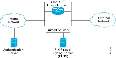
The Cisco IOS router must be configured to communicate with three separate networks: external, internal and trusted network. The interfaces that can be used with each Cisco IOS router are listed in the appendices of this document. The trusted network contains the PFSS server for collection of syslog audit data. The PFSS is to be connected to the Cisco IOS\Firewall enabled router such that the network interface of the PFSS is only accessible by the TSF. This may be achieved by either directly connecting the PFSS to the router, or indirectly over the trusted network.
The Cisco 8xx, Cisco 38xx and Cisco 72/73xx series of routers are modular and include at least two Fast Ethernet interfaces. When the TOE consists of one of these series, a third interface is required to connect to the Trusted Network. (See Figure 1.)
Figure 1
Typical Configuration for a Cisco 28xx, 38xx, and Cisco 72xx/73xx
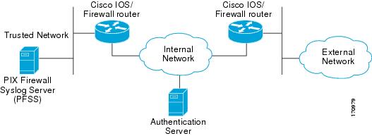
The Cisco 87x and Cisco 18xx series of routers are fixed configuration with a maximum of two Fast Ethernet interfaces. When the TOE consists of one of these series, a second instance of the TOE is required to protect access to the Trusted Network. (See Figure 2.)
Figure 2
Typical Configuration for Cisco 87xx and Cisco 18xx
Built in switch and modular switch options can be used to connect the trusted network to the router. To use this option, the administrator must define a VLAN interface on the router that is accessible to the PFSS server. Note: when the HWIC is used to connect to the Trusted Network additional networks can not be attached to other ports on the HWIC.
For a description of configuring VLAN interfaces with the Cisco HWIC-4ESW and HWIC-D-9ESW EtherSwitch Interface Cards as well as the onboard switch modules, see the "VLAN Configuration: Example" from the following link:
VLAN Configuration Example
Router# vlan databaseRouter(vlan)# vlan 2VLAN 2 modified:Router(vlan)# exitAPPLY completed.Exiting....Router# configure terminalRouter(config)# interface vlan 2Router(config-if)# ip address 10.150.0.1 255.255.255.0Router(config-if)# no shutRouter(config-if)# interface FastEthernet 2Router(config-if)# no shutRouter(config-if)# switchport mode accessRouter(config-if)# switchport access vlan 2Router(config-if)# exitTime Sources
Routers configured in accordance with the Cisco IOS/Firewall evaluation must timestamp system log messages. All routers in the Cisco IOS/Firewall evaluation Cisco IOS have internal real time clocks, these clocks provide reliable time stamp for audit logs. Administrators are required to check the system time on a regular basis and adjust it as necessary to maintain accurate time.
Administrative Roles
The TOE contains three administrative roles for use in the evaluated configuration: privileged, semi-privileged and audit administrators.
Semi-privileged administrator is the role with access to the console or SSH session on the Cisco IOS router. This role is automatically assigned when a user account is created on the Cisco IOS router. The privileged administrator is any administrator with knowledge of the "enable" password on the router. Privileged access is defined by any privilege level entering an enable password after their individual login. The audit administrator is the role assigned to a user that logs in and reviews the information recorded by the PFSS application.
Privilege Levels
The default configuration for Cisco IOS based networking devices uses privilege level 1 for user EXEC mode and privilege level 15 for privileged EXEC. The commands that can be run in user EXEC mode at privilege level 1 are a subset of the commands that can be run in privileged EXEC mode at privilege 15. The privilege command is used to move commands from one privilege level to another.
Caution
Access Control (Router)
The Cisco IOS router must be configured to authenticate both unprivileged and privileged (enable mode) access to the command line interface using a username and password for each administrator and one password for the enable command. When setting passwords on the TOE, please reference the TOE Password Complexity section. Individual administrator password should be kept secret, the enable password should only be told to administrators in a position of trust, who also have a need to know the enable password. When creating administrator accounts, ensure all passwords are configured to be encrypted
Administrator account access is to be restricted to a specified number of authentication attempts before the administrator account in question is locked out. The account then requires unlocking by an authorized administrator before it can be used again. The evaluated configuration requires that the threshold for unsuccessful authentication attempts is set.
Caution
TOE Password Complexity
To ensure proper protection of each administrator account, passwords MUST be:
•
•
•
Access Control (PFSS)
Access control is also required to be set on the PIX Firewall Syslog Server (PFSS) to protect the audit records from unauthorized deletion or modification. See the Windows 2000 user manuals for more information on how to set access controls in Windows. Access controls for the PFSS should be set to only allow the TOE's authorized administrators access to log on to the Windows 2000 operating system and to access the PFSS service. Only Privileged Authorized Administrators should be provided with administrator access. This level of restriction is important to maintain the evaluated configuration, the PFSS should not be used for any functions other than those related to the TOE.
Remote Administration and Management
If the Cisco IOS router is to be remotely administered, then the management station must be connected to a trusted network and SSH must be used to connect to the router. The ability to use telnet to remotely connect to the TOE is disabled by default in the evaluated configuration and should not be enabled. The use of SSH for remote administration requires the use of an external AAA server to provide one time authentication. For information on configuration of the router to use an external AAA server, see the Enabling Remote AAA services section.
Logging and Messages
Monitoring activity in the log files is an important aspect of your network security and should be conducted regularly. Monitoring the log files lets you take appropriate and timely action when you detect breaches of security or events that are likely to lead to a security breach in the future. Use the PIX Firewall Syslog Server (PFSS) or the show logging command on the router to view log files and messages. For configuration details, see Message Logging in Table 5.
Access Lists
The access-list command operates on a first match basis. Therefore, the last rule added to the access list is the last rule checked. The administrator should make a note of the last rule during initial configuration, because it may impact the remainder of the rule parsing. The evaluated configuration requires that the TOE Access control lists (ACLs) are to be configured to drop all packet flows as the default rule.
To enable logging of access-list matches, the log keyword should be used with access-list definitions.
Wireless Networking Features
The scope of the Common Criteria evaluation for Cisco IOS Firewall does not include the use of wireless networking features. In order to achieve an evaluated configuration, all wireless network interfaces are to be disabled. To disable an interface use the command:
interface <interface name> to enter configuration mode for the specified interface.
shutdown to change the state of the interface to administratively down or disabled.
For information on disabling network interfaces see the description of the interface shutdown command:
/en/US/docs/ios/12_2/interface/command/reference/irfshoip.html#wp1018004
Monitoring and Maintenance
Cisco IOS routers provide several ways to monitor their operation, from logs to messages.
•
•
Installation Notes
Table 4 Installation Documentation for Cisco IOS/Firewall Hardware Platforms
Cisco 8xx Series routers
Cisco 850 Series and Cisco 870 Series Access Routers Cabling and Setup Quick Start Guide (no cd location yet)
Cisco 180x Series routers
Cisco 1801, Cisco 1802, and Cisco 1803 Integrated Services Routers Cabling and Installation (no cd location yet)
Cisco 181x Series routers
Cisco 1811 and 1812 Integrated Services Router Cabling and Installation (no cd location yet)
Cisco 2800 Series routers
Cisco 2800 Series Integrated Services Routers Quick Start Guide (no cd location yet)
http://www.cisco.com/univercd/cc/td/doc/product/access/acs_mod/2800/qsg/2800_qsg.pdfCisco 3800 Series routers
Cisco 3800 Series Integrated Services Routers Quick Start Guide (no cd location yet)
http://www.cisco.com/univercd/cc/td/doc/product/access/acs_mod/3800/qsg/rb_qsg.htmCisco 7200 and 7300 Series routers
Cisco 7204 Installation and Configuration Guide
http://www.cisco.com/univercd/cc/td/doc/product/core/7204/7204ig/Cisco 7206 Installation and Configuration Guide
http://www.cisco.com/univercd/cc/td/doc/product/core/7206/7206ig/Cisco 7301 Router Quick Start Guide
http://www.cisco.com/univercd/cc/td/doc/product/core/7301/5341q.pdf
Verification of Image and Hardware
To verify that the Cisco IOS router software and hardware have not been tampered with during delivery, execute the following procedures.
1.
2.
3.
4.
5.
http://www.cisco.com/cisco/web/download/index.html
6.
7.
Cisco IOS Configuration Fundamentals and Network Management Configuration Guide, Release 12.31
Part 2: File Management
Loading and Maintaining System Images
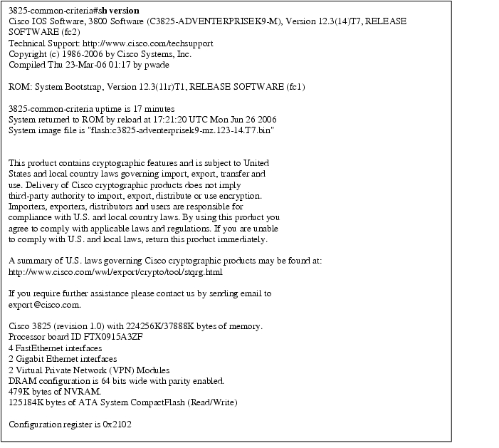
Start your Cisco IOS router as described in the installation documentation (see Table 4 above). Confirm that your Cisco IOS router loads the image correctly, completes internal self-checks and displays the cryptographic export warning on the console. At the prompt, type the show version command. (See Figure 3) Verify that the version is one of the valid versions listed in Table 1. If the Cisco IOS image fails to load, or if the Cisco IOS version does not match one of the valid versions listed in Table 1, contact Cisco Technical Support.Figure 3
Example "show version" Output, Showing Cisco IOS Release Version
Configuration Notes
The Common Criteria Target of Evaluation (TOE) for Cisco IOS/Firewall defines the following security features:
•
•
•
•
•
Upon delivery, a Cisco IOS router is not configured to support any of the security functions described above. These functions must be explicitly configured as described in the product documentation and this document to ensure your Cisco IOS router is operating in accordance with Common Criteria evaluated Cisco IOS/Firewall configuration. It should be noted that the PIX Firewall Syslog Server (PFSS) is also required in the Common Criteria evaluated Cisco IOS/Firewall configuration. Therefore the Cisco IOS router must not be connected to an untrusted network until these security features have been configured in accordance with this documentation. The installation guide for this software is contained in the PIX Firewall Syslog Server Release Notes.
Note
Security Features
The configuration information provided in this document should be followed when the particular feature of the TOE is to be configured. Note that all configuration commands listed in this document require to be entered as a privilege level 15 administrator. Where no evaluation specific guidance has been provided, Security features of the TOE should be configured as described in the following documentation:
Table 5 Evaluated Security Features for Cisco IOS Routers
Packet filtering
Cisco IOS Security Configuration Guide1
Part 3: Traffic Filtering and Firewalls
Access Control Lists: Overview and GuidelinesMessage Logging
Cisco IOS Configuration Fundamentals and Network Management Configuration Guide2
Part 3: System and Network Management
Troubleshooting and Fault ManagementPIX Firewall Syslog Sever Installation Instructions (Appendix B of this document)
User Authentication
Cisco IOS Security Configuration Guide1
Part 5: Other Security Features
Configuring Passwords and PrivilegesRSA Token implementation guidance (Appendix C of this document)
Time Management
Cisco IOS Configuration Fundamentals and Network Management Configuration Guide2
Part 3: System and Network Management
Performing Basic System ManagementRemote Management
Cisco IOS Security Configuration Guide1
Part 5: Other Security Features
Configuring Secure Shell
1 http://www.cisco.com/univercd/cc/td/doc/product/software/ios123/123cgcr/sec_vcg.htm
2 http://www.cisco.com/univercd/cc/td/doc/product/software/ios123/123cgcr/cfun_vcg.htm
Saving Configuration
Cisco IOS uses both a running configuration and a starting configuration. Configuration changes affect the running configuration, in order to save that configuration the running configuration (held in memory) must be copied to the startup configuration. This may be achieved by either using the write memory command or the copy system:running-config nvram:startup-config command. These commands should be used frequently when making changes to the configuration of the Cisco IOS router. If the Cisco IOS router reboots and resumes operation when uncommitted changes have been made, these changes will be lost and the Cisco IOS router will revert to the last configuration saved.
Access Controls
When setting passwords on the TOE, please reference the TOE Password Complexity section.
Administrator account access is to be restricted to a specified number of authentication attempts before the administrator account in question is locked out. The account then requires unlocking by an authorized administrator before it can be used again. The evaluated configuration requires that the lockout occurs after a specified threshold for unsuccessful authentication attempts. Use the following command, with `<x>' being the required number of attempts before lockout, to set the authentication failure threshold (the authentication threshold must be non zero):
aaa local authentication attempts max-fail <x>
In order to use "aaa" commands, some routers may require the entry of the aaa new-model command before the above command may be entered.
A locked user account may be unlocked by a privileged administrator by using the following command:
clear aaa local user lockout username [username]
The Cisco IOS router must be configured to use a username and password for each administrator and one password for the enable command. Ensure all passwords are stored encrypted by using the following command:
service password-encryption
When creating administrator accounts, all individual accounts are to be set to a privilege level of one. This is done by using the following commands:
username <name> password <password> to create a new username and password combination, and
username <name> privilege 1 to set the privilege level of <name> to 1
If the administrator forgets the password for a given TOE router and is unable to login, please visit the Cisco IOS Password Recovery site on cisco.com for instructions on how to recover.
http://www.cisco.com/en/US/products/sw/iosswrel/ps1831/products_tech_note09186a00801746e6.shtml
Disabling the HTTP Server
The scope of the Common Criteria evaluation for Cisco IOS Firewall does not include the HTTP Server feature. In order to achieve an evaluated configuration, the HTTP Server is to be disabled on the routers.
To disable the HTTP Server use the following commands:
Router#configure terminalEnter configuration commands, one per line. End with CNTL/Z.Router(config)#no ip http serverDisabling SNMP management
The scope of the Common Criteria evaluation for Cisco IOS Firewall does not include Management access of the Router via SNMP. In order to achieve an evaluated configuration SNMP is to be disabled on the routers.
To disable the SNMP Server use the following commands:
Router (config)#no snmp-serverDisabling H.323 and Session Initiation Protocol (SIP)
The router, by default, responds to H.323 and SIP services on TCP ports 1720 and 5060. Cisco gateways with SIP functionality listen to port 5060 by default.
You can disable the router listening on port 5060 by issuing this command:
Router(config)# sip-ua
Router(config-sip-ua)# no transport tcp
Router(config-sip-ua)# no transport udp
Cisco gateways running Cisco IOS® versions that support SIP protocol listen to TCP or UDP port 5060 by default, even when the gateway is not explicitly configured for SIP.
Disabling Source Routing
The IP protocol supports source routing options that allow the sender of an IP datagram to control the route that datagram will take toward its ultimate destination, and generally the route that any reply will take. These options are rarely used for legitimate purposes in real networks. Some older IP implementations do not process source-routed packets properly, and it may be possible to crash machines running these implementations by sending them datagrams with source routing options.
A Cisco router with no ip source-route set will never forward an IP packet which carries a source routing option. You should use this command unless you know that your network needs source routing.
Router(config)# no ip source-routeEnabling Time-Stamps
By default, all audit records are not stamped with the time and date, which are generated from the system clock when an event occurs.
The Common Criteria evaluated Cisco IOS/Firewall requires that the time-stamp feature be enabled on your Cisco IOS router. To enable the timestamp of audit events, use the following command
Router (config)# service timestamps log datetimeTo ensure that the timestamp option is meaningful, the system clock in your Cisco IOS router must be set correctly (see following section).
Audit Events
To generate logging messages for failed and successful login attempts in the evaluated configuration, issue the login on-failure and login on-success commands.
Router(config)# login on-failureRouter(config)# login on-successRouter(config)# login block-for 1 attempts 3 within 30Further enhancements to the Configuration Change Logging process were implemented in Cisco IOS Release 12.3(14)T. These enhancements support an effort to ensure the logging process meets the requirements set forth in the Conformance to Common Criteria, Evaluation Assurance Level 4+ (EAL4+) Firewall Protection Profiles. These enhancements include changes to meet the following requirements:
•
•
Router(config)# archiveRouter(config-archive)# log configRouter(config-archive-log-cfg)# logging enableRouter(config-archive-log-cfg)# logging size 1000Router(config-archive-log-cfg)# hidekeysRouter(config-archive-log-cfg)# notify syslogRouter(config-archive-log-cfg)# exitRouter(config-archive)# exitSetting the Default Access Control List (ACL) / Firewall Policy
The evaluated configuration requires that the TOE Access control lists (ACLs) are to be configured to drop all packet flows as the default rule. This can be achieved by including an ACL rule to drop all packets as the last rule in the ACL configuration.
A privileged authorized administrator may manipulate the ACLs using the commands ip inspect, access-list and access-group as described in the Cisco IOS command reference.
Access lists must be configured on the TOE to prevent spoofing of external or internal addresses through the opposite interface and also to block broadcast source address and loopback source address traffic. These access control lists are required for compliance with the Application Firewall Protection Profile.
These access lists must be integrated with the defined security policy for your TOE router. Enabling just these access lists with no permits will result in traffic being dropped.
In this example, we are assuming that interface GigabitEthernet0/0 is the external interface, and is assigned an IP address of 10.200.1.1. Interface GigabitEthernet0/1 is the internal interface and is assigned an IP address of 10.100.1.1.
Note: Access lists must be created on the TOE router to allow communication between the third-party authentication server and the TOE router.
Enter configuration mode to begin creating ACL's.
Router# configure terminalEnter configuration commands, one per line. End with CNTL/Z.To prevent the passing of traffic with an internal source address on the external Interface, apply the following access control list to the external interface:
Router(config)# access-list 199 deny ip 10.100.0.0 0.0.255.255 any log-inputTo prevent the passing of traffic with an external source address on the internal Interface, apply the following access control list to the internal interface:
Router(config)# access-list 100 deny ip 10.200.0.0 0.0.255.255 any log-inputTo prevent the passing of traffic with a broadcast or loopback address on either interface, apply the following access control list to both interfaces:
Router(config)# access-list 100 deny ip 224.0.0.0 15.255.255.255 any log-inputRouter(config)# access-list 100 deny ip 255.255.255.255 0.0.0.0 any log-inputRouter(config)# access-list 100 deny ip 127.0.0.0 0.255.255.255 any log-inputRouter(config)# access-list 199 deny ip 224.0.0.0 15.255.255.255 any log-inputRouter(config)# access-list 199 deny ip 255.255.255.255 0.0.0.0 any log-inputRouter(config)# access-list 199 deny ip 127.0.0.0 0.255.255.255 any log-inputConfigure a default firewall policy, to watch all TCP, UDP and ICMP packets. To prevent the loss of audit data, the Cisco IOS Firewall will not allow new sessions to pass through if it loses the connection to the TCP syslog server. The firewall inspect policy needs to be applied to all TOE network interfaces.
Router(config)# ip inspect name sample_policy tcpRouter(config)# ip inspect name sample_policy udpRouter(config)# ip inspect name sample_policy icmpApply the policies to the appropriate interfaces.
Router(config)# interface GigabitEthernet0/0Router(config-if)# ip access-group 199 inRouter(config-if)# ip inspect sample_policy inRouter(config)# interface GigabitEthernet0/1Router(config-if)# ip access-group 100 inRouter(config-if)# ip inspect sample_policy inIf remote administration is required, SSH has to be explicitly allowed through either the internal or external interfaces.
Router# configure terminalEnter configuration commands, one per line. End with CNTL/Z.Router(config)# access-list 199 permit tcp host 10.200.0.1 host 10.200.0.1 eq 22 log-input
Caution
Enabling Remote and Local AAA services
For remote management via SSH, the evaluated configuration requires a remote AAA service that provides one time authentication. The configuration of AAA services will depend on the environment in which the TOE is to operate and may differ between installations. In order to maintain a level of flexibility to the possible configuration of the TOE, it is important to follow the guidance material relevant to your installation (12.3 for 12.3T installations, 12.4T for 12.4T installations). Specific guidance for the configuration of the TOE to use an external AAA server may be found in the following locations:
Cisco IOS Security Configuration Guide (12.3 and 12.4T versions)
Part 1: Authentication, Authorization, and Accounting (AAA)
AAA OverviewCisco IOS Security Configuration Guide (version for 12.3)
Part 5: Other Security Features
Configuring Secure Shell
New Feature: SSH Terminal-Line AccessCisco IOS Security Configuration Guide (version for 12.4T)
Configuring Login Authentication Using AAA
Note
Configuring Firewall Fail Close Functionality
The evaluated configuration requires that the firewall fail close functionality is enabled. Since this functionality is not enabled by default the following command must be entered at the CLI to configure this option: logging host <ip> transport tcp port <port> audit
Router# configure terminalEnter configuration commands, one per line. End with CNTL/Z.Router(config)# logging host 10.150.0.206 transport tcp port 1470 auditRouter(config)# exitThis function allows for the firewall to disallow any new connection attempts in the audit logging system failure. In the above command <ip> and <port> are the IP address of the PIX Firewall Syslog Server and the port that the service is listening on (the default port for TCP Syslog is 1468). This command also enables the use on TCP Syslog for the transfer of audit data.
When the PFSS service (syslog server) is restarted and the connection to the router is dropped, sometimes the router re-establishes the TCP syslog session on its own and other times won't re-establish the connection to the listening Windows box unless the router is reloaded. This condition exists when the syslog server is rebooted or goes offline for an extended period of time.
The router will attempt to reconnect for a limited time. The limited reconnect retries may be exhausted by the time the syslog server comes back operational or when the IP connection stabilizes, and hence the syslog server may appear not connected.
The workaround for this issue is to remove the "logging host..." entry for that syslog server and re-add it. By adding it back via the CLI the connection retry is reset to the maximum and the syslog server should reconnect.
Setting the System Clock
To provide accurate time stamps for logging, the system clock must be set. Some models of Cisco IOS routers have real time clocks that maintain real time when the Cisco IOS router is powered down. These real time clocks are used to initialize the system clock at startup. Other models of Cisco IOS routers do not have a real time clock that will maintain the date and time after shutdown and must obtain the correct date and time from a reliable time source. Although Cisco IOS routers are capable of using the Network Time Protocol (NTP), this function is not enabled in the evaluated configuration. If the Cisco IOS router does not have an internal hardware clock the time is required to be set manually at startup by a privileged authorized administrator using the clock command as follows:
clock set <hh:mm:ss day month year> where hh;mm;ss is 24 hour time, day is the current date, month and year are the name of the month and year in full. Eg: clock set 08:52:00 8 February 2005.
Configuring Secure Shell
If the remote management over Secure Shell (SSH) is to be enabled, it is required to be configured to use 3DES encryption in accordance with the evaluated configuration.
Router# configure terminalEnter configuration commands, one per line. End with CNTL/Z.Router(config)# hostname sample-hostRouter(config)# ip domain name cisco.comRouter(config)# crypto key generate rsaThe name for the keys will be: sample-host.cisco.com Choose the size of the key modulus in the range of 360 to 2048 for your General Purpose Keys. Choosing a key modulus greater than 512 may take a few minutes.
How many bits in the modulus [512]: 2048 <enter>% Generating 2048 bit RSA keys ...[OK]Router(config)# ip ssh logging eventsRouter(config)# ip ssh version 2Router(config)# line vty 0 4Router(config-line)# transport input sshRouter(config-line)# exitRouter(config)# exitAdditional information for configuring this feature can be found in the following documentation:
Cisco IOS Security Configuration Guide
Part 5: Other Security Features
Configuring Secure ShellNote that remote AAA authentication is required to be used to authenticate SSH remote management in the evaluated configuration. For information on configuring AAA services see the section Enabling Remote and Local AAA services in this document.
MD5 Hash Values for Cisco IOS Software Images
Further verification of MD5 hash values can be obtained by contacting Cisco Technical support.
Related Documentation
Use this document in conjunction with the Cisco IOS router documentation at the following locations:
http://www.cisco.com/univercd/cc/td/doc/product/software/ios123/index.htm
Obtaining Documentation
The following sections provide sources for obtaining documentation from Cisco Systems.
World Wide Web
You can access the most current Cisco documentation on the World Wide Web at the following sites:
Documentation CD-ROM
Cisco documentation and additional literature are available in a CD-ROM package, which ships with your product. The Documentation CD-ROM is updated monthly and may be more current than printed documentation. The CD-ROM package is available as a single unit or as an annual subscription.
Obtaining Technical Assistance
Cisco provides Cisco.com as a starting point for all technical assistance. Customers and partners can obtain documentation, troubleshooting tips, and sample configurations from online tools. For Cisco.com registered users, additional troubleshooting tools are available from the TAC website.
Cisco.com
Cisco.com is the foundation of a suite of interactive, networked services that provides immediate, open access to Cisco information and resources at anytime, from anywhere in the world. This highly integrated Internet application is a powerful, easy-to-use tool for doing business with Cisco.
Cisco.com provides a broad range of features and services to help customers and partners streamline business processes and improve productivity. Through Cisco.com, you can find information about Cisco and our networking solutions, services, and programs. In addition, you can resolve technical issues with online technical support, download and test software packages, and order Cisco learning materials and merchandise. Valuable online skill assessment, training, and certification programs are also available.
Customers and partners can self-register on Cisco.com to obtain additional personalized information and services. Registered users can order products, check on the status of an order, access technical support, and view benefits specific to their relationships with Cisco.
To access Cisco.com, go to the following website:
http://www.cisco.comTechnical Assistance Center
The Cisco TAC website is available to all customers who need technical assistance with a Cisco product or technology that is under warranty or covered by a maintenance contract.
Contacting TAC by Using the Cisco TAC Website
If you have a priority level 3 (P3) or priority level 4 (P4) problem, contact TAC by going to the TAC website:
P3 and P4 level problems are defined as follows:
•
•
In each of the above cases, use the Cisco TAC website to quickly find answers to your questions.
To register for Cisco.com, go to the following website:
http://www.cisco.com/register/
If you cannot resolve your technical issue by using the TAC online resources, Cisco.com registered users can open a case online by using the TAC Case Open tool at the following website:
http://www.cisco.com/tac/caseopen
Contacting TAC by Telephone
If you have a priority level 1 (P1) or priority level 2 (P2) problem, contact TAC by telephone and immediately open a case. To obtain a directory of toll-free numbers for your country, go to the following website:
http://www.cisco.com/warp/public/687/Directory/DirTAC.shtml
P1 and P2 level problems are defined as follows:
•
•
This document is to be used in conjunction with the documents listed in the Related Documentation section.
Any Internet Protocol (IP) addresses used in this document are not intended to be actual addresses. Any examples, command display output, and figures included in the document are shown for illustrative purposes only. Any use of actual IP addresses in illustrative content is unintentional and coincidental.
© 2006 Cisco Systems, Inc. All rights reserved.Appendix A.1: Cisco 1841 Series Modules
Table 8 lists the modules and interface cards supported by the Cisco 1841 router.
Table 8 Modules and Interface Cards Supported by the Cisco 1841 Router
HWIC-4ESW
4-port single-wide 10/100 BaseT Ethernet switch HWIC
X
WIC-1T
1-port serial WIC
X
WIC-2T
2-port serial WIC
X
WIC-2A/S
2-port asynchronous or synchronous serial WIC
X
WIC-1DSU-T1-V2
1-port T1/Fractional-T1 CSU/DSU WIC
X
WIC-1DSU-56K4
1-port 4-wire 56-/64-kbps CSU/DSU WIC
X
WIC-1B-U-V2
1-port ISDN Basic Rate Interface (BRI) with integrated NT1 (U interface)
X
WIC-1B-S/T-V3
1-port ISDN BRI with S/T interface
X
WIC-1ADSL
1-port asymmetric DSL (ADSL) over basic-telephone-service WIC
X
WIC-1ADSL-DG
1-port ADSL over basic telephone service with dying-gasp1 WIC
X
WIC-1ADSL-I-DG
1-port ADSL over ISDN with dying-gasp1 WIC
X
WIC-1SHDSL
1-port G.shdsl WIC (two wire only)
X
WIC-1SHDSL-V2
1-port G.shdsl WIC (two or four wire)
X
WIC-1AM
1-port analog modem WIC
X
WIC-2AM
2-port analog modem WIC
X
WIC-1AM-V2
1-port analog modem WIC
X
WIC-2AM-V2
2-port analog modem WIC
VWIC-1MFT-T1
1-port RJ-48 multiflex trunk-T1
X (data only)
VWIC-2MFT-T1
2-port RJ-48 multiflex trunk-T1
X (data only)
VWIC-2MFT-T1-DI
2-port RJ-48 multiflex trunk-T1 with drop and insert
X (data only)
VWIC-1MFT-E1
1-port RJ-48 multiflex trunk-E1
X (data only)
VWIC-1MFT-G703
1-port RJ-48 multiflex trunk-G.703
X (data only)
VWIC-2MFT-E1
2-port RJ-48 multiflex trunk-E1
X (data only
VWIC-2MFT-E1-DI
2-port RJ-48 multiflex trunk-E1 with drop and insert
X (data only
VWIC-2MFT-G703
2-port RJ-48 multiflex trunk-G.703
X (data only
AIM-VPN/BPII-PLUS
Enhanced-performance DES, 3DES, AES, and compression VPN encryption AIM
X
MEMUSB-64FT
64 MB USB Flash
X
MEMUSB-128FT
128 MB USB Flash
X
MEMUSB-256FT
256 MB USB Flash
X
Aladdin "eToken Pro USB"
Aladdin "eToken Pro USB"
(See www.aladdin.com/etoken/)X
Appendix A.2: Cisco 2800 Series Module
Table 9 lists the modules supported by the Cisco 2800 series router.
Table 9 Network Modules Supported by the Cisco 2800 Series Router
NM-16ESW
16-port 10/100 Cisco EtherSwitch® Network Module
No
X
X
X
NM-16ESW-1GIG
16-port 10/100 Cisco EtherSwitch Network Module with 1 Gigabit Ethernet (1000BASE-T) port
No
X
X
X
NM-16ESW-PWR
16-port 10/100 Cisco EtherSwitch Network Module with in-line power support
No
X
X
X
NM-16ESW-PWR-1GIG
16-port 10/100 Cisco EtherSwitch Network Module with in-line power and Gigabit Ethernet
No
X
X
X
NMD-36ESW
36-port 10/100 Cisco EtherSwitch High-Density Services Module (HDSM)
No
No
No
X
NMD-36ESW-2GIG
36-port 10/100 Cisco EtherSwitch HDSM with 1 Gigabit Ethernet (1000BASE-T) port
No
No
No
X
NMD-36ESW-PWR
36-port 10/100 Cisco EtherSwitch HDSM with in-line power support
No
No
No
X
NMD-36ESW-PWR-2G
36-port 10/100 Cisco EtherSwitch HDSM with in-line power and Gigabit Ethernet
No
No
No
X
NM-1T3/E3
1-port clear-channel T3/E3 network module
No
X
X
X
NM-1HSSI
1-port High-Speed Serial Interface (HSSI) network module
No
X
X
X
NM-4A/S
4-port asynchronous/synchronous serial network module
No
X
X
X
NM-8A/S
8-port asynchronous/synchronous serial network module
No
X
X
X
NM-16A/S
16-port asynchronous/synchronous serial network nodule
No
X
X
X
NM-16A
16-port asynchronous serial network module
No
X
X
X
NM-32A
32-port asynchronous serial network module
No
X
X
X
NM-1CE1T1-PRI
1-port Channelized E1/T1/ISDN PRI network module
No
X
X
X
NM-2CE1T1-PRI
2-port Channelized E1/T1/ISDN PRI network module
No
X
X
X
NM-4B-S/T
4-port ISDN BRI network module (S/T interface)
No
X
X
X
NM-4B-U
4-port ISDN BRI network module with integrated Network Termination 1 (NT1) (U interface)
No
X
X
X
NM-8B-S/T
8-port ISDN BRI network module (S/T interface)
No
X
X
X
NM-8B-U
8-port ISDN BRI network module with integrated NT1 (U interface)
No
X
X
X
NM-1A-T3
1-port DS-3 ATM network module
No
X
X
X
NM-1A-E3
1-port E3 ATM network module
No
X
X
X
NM-8AM-V2
8-port analog modem network module with v.92
No
X
X
X
NM-16AM-V2
16-port analog modem network module with v.92
No
X
X
X
NM-HD-1V
1-slot IP Communications voice and fax network module
No
X
X
X
NM-HD-2V
2-slot IP Communications voice and fax network module
No
X
X
X
NM-HD-2VE
2-slot IP Communications enhanced voice and fax network module
No
X
X
X
NM-HDA-4FXS
High-density analog voice and fax network module with 4 FXS slots
No
X
X
X
NM-HDV2
IP Communications high-density voice and fax network module
No
X
X
X
NM-HDV2-1T1/E1
1-port T1/E1 IP Communications high-density voice and fax network module
No
X
X
X
NM-HDV2-2T1/E1
2-port T1/E1 IP Communications high-density voice and fax network module
No
X
X
X
NM-HDV=
High Density Voice/Fax Network Module (Single VIC Slot)
No
X
X
X
NM-HDV-1T1-12
1-port 12-channel T1 voice and fax network module
No
X
X
X
NM-HDV-1T1-24
1-port 24-channel T1 voice and fax network module
No
X
X
X
NM-HDV-1T1-24E
Single-port 24 enhanced channel T1 voice and fax network module
No
X
X
X
NM-HDV-2T1-48
2-port 48-channel T1 voice and fax network module
No
X
X
X
NM-HDV-1E1-12
1-port 12-channel E1 voice and fax network module
No
X
X
X
NM-HDV-1E1-30
1-port 30-channel E1 voice and fax network module
No
X
X
X
NM-HDV-1E1-30E
1-port 30-enhanced-channel E1 voice and fax network module
No
X
X
X
NM-HDV-2E1-60
2-port 60-channel E1 voice and fax network module
No
X
X
X
NM-HDV-1J1-30
1-port 30-channel J1 high-density voice network module
No
X
X
X
NM-HDV-1J1-30E
1-port 30-enhanced-channel J1 high-density voice network module
No
X
X
X
NM-HDV-FARM-C36
36-port transcoding and conferencing DSP farm
No
X
X
X
NM-HDV-FARM-C54
54-port transcoding and conferencing DSP farm
No
X
X
X
NM-HDV-FARM-C90
90-port transcoding and conferencing DSP farm
No
X
X
X
NM-CE-BP-40G-K9
Cisco Content Engine Network Module, basic performance, 40-GB IDE hard disk
No
X
X
X
NM-CE-BP-80G-K9
Cisco Content Engine Network Module, basic performance, 80-GB IDE hard disk
No
X
X
X
NM-CE-BP-SCSI-K9
Cisco Content Engine Network Module, basic performance, Small Computer System Interface (SCSI) controller
No
X
X
X
NM-CIDS-K9
Cisco IDS Network Module
No
X
X
X
NM-CUE
Cisco Unity Express Voice-Mail Network Module
No
X
X
X
NM-NAM
Cisco 2600, 3660, and 3700 series network analysis module
No
X
X
X
NM-AIC-64
Alarm monitoring and control network module
No
X
X
X
NM-CEM-4SER
4-port serial Circuit Emulation over IP (CEoIP) network module
No
X
X
X
NM-CEM-T4E1
4-port T1/E1 Circuit Emulation over IP (CEoIP) network module
No
X
X
X
HWIC-4ESW
4-port single-wide 10/100BaseT Ethernet switch HWIC
X
X
X
X
HWIC-D-9ESW
9-port double-wide 10/100BaseT Ethernet switch HWIC
X
X
X
X
HWIC-4ESW-POE
4-port Ethernet switch HWIC, Power over Ethernet capable
X
X
X
X
HWIC-D-9-ESW-POE
9-port Ethernet switch HWIC, Power over Ethernet capable
X
X
X
X
HWIC-1GE-SFP
No
X
X
X
WIC-1T
1-port high-speed serial WIC
X
X
X
X
WIC-2T
2-port high-speed serial WIC
X
X
X
X
WIC-2A/S
2-port asynchronous/synchronous serial WIC
X
X
X
X
WIC-1DSU-T1-V2
1-port T1/Fractional-T1 DSU/CSU WIC
X
X
X
X
WIC-1DSU-56K4
1-port 4-wire 56-/64-kbps CSU/DSU WIC
X
X
X
X
WIC-1B-U-V2
1-port ISDN BRI with integrated NT1 (U interface)
X
X
X
X
WIC-1B-S/T-V3
1-port ISDN BRI with S/T interface
X
X
X
X
WIC-1ADSL
1-port asymmetric DSL (ADSL) over POTS service WIC
X
X
X
X
WIC-1ADSL-DG
1-port ADSL over basic telephone service with dying-gasp WIC
X
X
X
X
WIC-1ADSL-I-DG
1-port ADSL over ISDN with dying-gasp WIC
X
X
X
X
WIC-1SHDSL
1-port G.shdsl WIC (two wire only)
X
X
X
X
WIC-1SHDSL-V2
1-port G.shdsl WIC (two or four wire)
X
X
X
X
WIC-1AM
1-port analog modem WIC
X
X
X
X
WIC-2AM
2-port analog modem WIC
X
X
X
X
WIC-1AM-V2
1-port analog modem WIC
X
No
No
No
WIC-2AM-V2
2-port analog modem WIC
X
No
No
No
VWIC-1MFT-T1
1-port RJ-48 multiflex trunk-T1
X
X
X
X
VWIC-2MFT-T1
2-port RJ-48 multiflex trunk-T1
X
X
X
X
VWIC-2MFT-T1-DI
2-port RJ-48 multiflex trunk-T1 with drop and insert
X
X
X
X
VWIC-1MFT-E1
1-port RJ-48 multiflex trunk-E1
X
X
X
X
VWIC-1MFT-G703
1-port RJ-48 multiflex trunk-G.703
X
X
X
X
VWIC-2MFT-E1
2-port RJ-48 multiflex trunk-E1
X
X
X
X
VWIC-2MFT-E1-DI
2-port RJ-48 multiflex trunk-E1 with drop and insert
X
X
X
X
VWIC-2MFT-G703
2-port RJ-48 multiflex trunk-G.703
X
X
X
X
VIC-2DID
2-port DID voice and fax interface card
X
X
X
X
VIC-1J1
1-port digital VIC (J1) for Japan
No
X
X
X
VIC-4FXS/DID
4-port FXS or DID VIC
X
X
X
X
VIC2-2FXS
2-port VIC-FXS
X
X
X
X
VIC2-2FXO
2-port VIC-FXO (universal)
X
X
X
X
VIC2-4FXO
4-port VIC-FXO (universal)
X
X
X
X
VIC2-2E/M
2-port VIC-E&M
X
X
X
X
VIC2-2BRI-NT/TE
2-port VIC card-BRI (NT and TE)
X
X
X
X
MEMUSB-64FT
64 MB USB Flash
X
No
No
No
MEMUSB-128FT
128 MB USB Flash
X
No
No
No
MEMUSB-256FT
256 MB USB Flash
X
No
No
No
Aladdin "eToken Pro USB"
Aladdin "eToken Pro USB"
(See www.aladdin.com/etoken/)X
No
No
No
Appendix A.3: Cisco 3800 Series Module
Table 10 lists the modules supported by the Cisco 3800 series router.
Appendix A.4: Cisco 7000 Series Module Support
Table 11 lists the modules supported by the Cisco 7000 series router.
Appendix B: PIX Firewall Syslog Server (PFSS) Guidance
Installation Instructions
1.
2.
3.
TCP PORT = 1468
UDP PORT = 514
==> You must enter a port number greater than 1024 and less than 65536.
4.
% Disk Full - The percentage of the total disk size that is full that you wish the Syslog Server to stop at. (Default is 90%)
Disk Empty Watch - This is the number of seconds in interval that you wish the disk monitor to check to see if the disk is full when the disk is still empty. (Default is 5 seconds)
Disk Full Watch - This is the number of seconds in interval that you wish the disk monitor to check to see if the disk is empty when the disk is still full. (Default is 3 seconds)
5.
6.
-d < % Disk Full >
-t < TCP PORT >
-u < UDP PORT>
-e < Disk Empty Watch >
-f < Disk Full Watch >
For example, to set the % Disk Full to %35 and the TCP PORT to 1470, type -d 35 -t 1470.
Usage Instructions
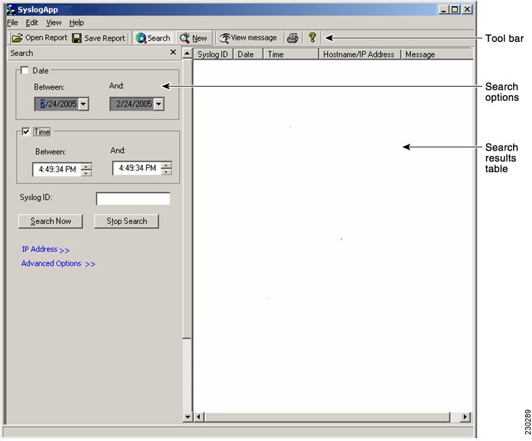
The PFSS is bundled with an executable application to conduct searching and sorting of the stored syslog records. The shortcut for this application is created on the desktop and in the existing program folder of PFSS. No changes can be done to the log files from the search/sort application.
The PFSS search/sort application is launched by clicking the short cut present in the desktop or the one present in the program folder. The initial screen of the application is given in Figure 4. The screen is divided into 3 parts:
1.
2.
3.
Figure 4
PFSS Search/Sort Screen
Controls in Tool Bar
The following controls are present in the toolbar:
1.
2.
3.
4.
5.
6.
Clicking the "Open Report" opens the already stored report files for viewing. "Save Report" saves the search results in two formats
1.
2.
In the .PFSS format there is a delimiter ($) in between the fields and when opened from the application the messages are shown in the search results table.
In the *.txt format the syslog message information is stored and will be opened in a notepad for viewing.
Clicking the "Search" in the tool bar enables and disables the search options dialog. The search options dialog can also be enabled using the menu "View—>Search".
Clicking the "New" in the tool bar, clears the existing search values and set the search fields in default values. The "New Search" can also be selected from "Edit—>New Search" menu.
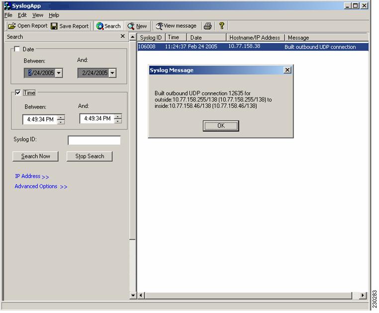
The "View message" will be enabled only when the user has selected a message displayed in the search table. The log message can also be viewed by double clicking the row as shown in Figure 5.
Figure 5 Syslog View Message
Fields in Search Options
The search options dialog has the following fields based on which searching will be done:
1.
2.
3.
4.
5.
The first 3 fields— namely Date, Time range selection and Syslog ID—are the most commonly used scenarios, and they are enabled by default; the other 2 fields are disabled by default.
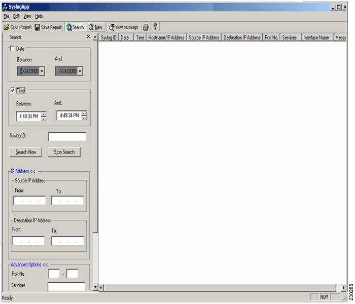
Clicking the "IP Address >> and Advanced Options >>" in the search options dialog, will enable and disable the fields like source and destination IP address, Services, Ports, Interface name etc. The full view of search options is given in Figure 6 and Figure 7 below.
Figure 6
Search With IP Address and Advanced Option Fields
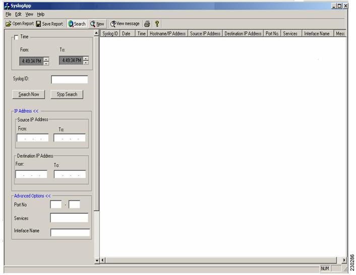
Figure 7
Search With IP Address and Advanced Option Fields (continued)
Search Results Table
The syslog messages which satisfy the search conditions are populated in the "Search results table". The following are the default columns present initially:
1.
2.
3.
4.
5.
Apart from the above columns, the user can select the following fields as columns in the search results table by going to "View—>Select columns" options. The optional fields are:
1.
2.
3.
4.
5.
The default columns cannot be deselected from the Search results table. Sorting can be done by clicking on the column headers. For example, to sort by "Syslog ID" click on the "Syslog ID" column header in the Search Results table.
Search/Sort Menu Structure:
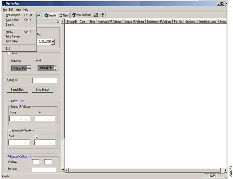
The "File" Menu has the options to Open, Save and Print the search reports as shown in Figure 8.
Figure 8
Search/Sort File Menu
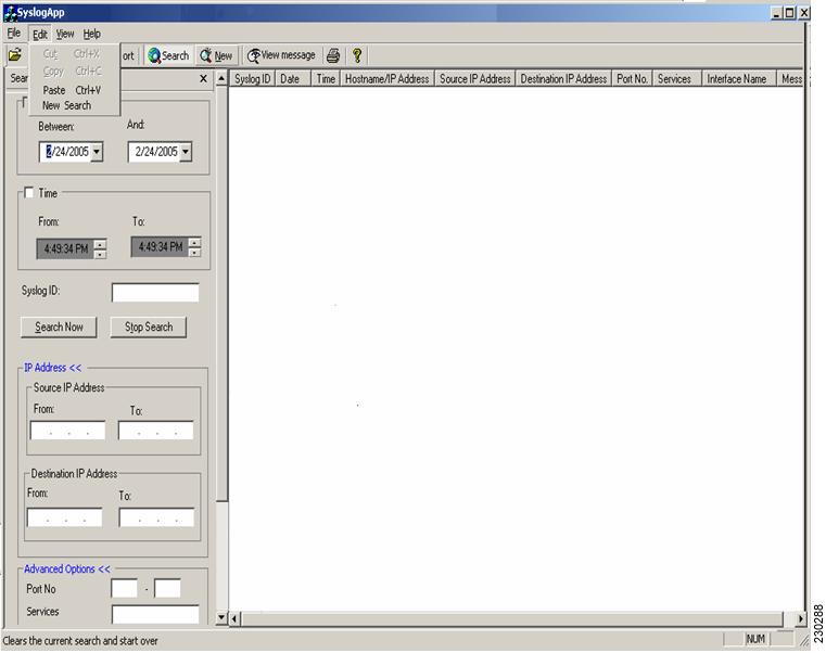
The "Edit" menu has options like cut, copy and paste like normal applications. "New Search" is the same as the "New" in the toolbar. It clears the current search fields and populates them with default values. The Edit menu is shown in Figure 9.
Figure 9
Search/Sort Edit Menu
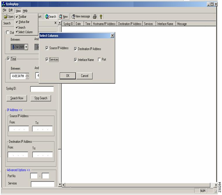
The "View" menu has the options to enable the toolbar, status bar, search options and Select Columns. "Select Columns" menu is used to customize the search results table. Not all the options in the search results table are customizable. The Syslog ID, Date, Time, Hostname/IP Address and log message fields will always be displayed. The other fields (Source and Destination IP Address, Port, Services and Interface name) can be enable or disabled by using the "Select Columns" dialog via the "Select Columns" menu as shown in Figure 10.
Figure 10
Search/Sort View Menu
I. Release Notes for PIX Firewall Syslog Server 5.1(2)
1.
2.
3.
II. Release Notes for PIX Firewall Syslog Server 5.1(1)
NOTES: For 5.1(1), per bug CSCdp45416, there are 2 changes made to PFSS:
1.
2.
Appendix C: RSA Token Implementation Guidance
Configuration Instructions
The following instructions cover the use of RSA tokens for remote access only.
1.
For Tacacs+-based Authentication
aaa new-modelaaa authentication login default tacacs+ line enableaaa authentication ppp default tacacs+tacacs-server host xxx.xxx.xxx.xxxtacacs-server timeout 120tacacs-server key "your key"For RADIUS-based authentication
aaa new-modelaaa authentication login default radius line enableaaa authentication ppp default radiusradius-server host xxx.xxx.xxx.xxx auth-port 1645 acct-port 1646 key "your key"radius-server timeout 120For additional information on configuring Cisco IOS to use RSA tokens, please see the RSA SecurID Ready Implementation Guide.