Feedback Feedback
|
Table Of Contents
Cisco 3800 Series Integrated Services Routers Quick Start Guide
Cisco One-Year Limited Warranty Terms
Documents, Equipment, and Tools
Items Included with Cisco 3800 Series Routers
Connecting the Routers to AC Power
Connecting the Router to DC Power
Connecting the Router to Backup Power
WAN, LAN, and Voice Connections
Verify the Front Panel LED Indications
Verify the Hardware Configuration
Interface Card in Network Module
Initial Configuration Using Cisco Router and Security Device Manager (SDM)
Initial Configuration Using the Setup Command Facility
Initial Configuration Using the Cisco CLI—Manual Configuration
Verify the Initial Configuration
Obtaining Technical Assistance
Cisco Technical Support Website
Definitions of Service Request Severity
Obtaining Additional Publications and Information
Quick Start Guide
Cisco 3800 Series Integrated Services Routers Quick Start Guide
INCLUDING LICENSE AND WARRANTY1 Cisco One-Year Limited Warranty Terms
There are special terms applicable to your hardware warranty and various services that you can use during the warranty period. Your formal Warranty Statement, including the warranties and license agreements applicable to Cisco software, is available on Cisco.com at the following URL: www.cisco.com/go/warranty.
You can also contact the Cisco service and support website for assistance: http://www.cisco.com/en/US/support/
2 Overview
The Cisco 3800 series integrated services routers include the Cisco 3825 and Cisco 3845 routers. Both routers support WAN interface cards (WIC), voice/WAN interface cards (VWICs), high-speed WAN interface cards (HWICs), and advanced integration modules (AIMs). These routers differ as follows:
•
Cisco 3825 routers support 2 network module slots. The lower network module slot, labeled 1, can hold either 1 single-wide network module or 1 extended single-wide network module. The upper network module slot, labeled 2, can hold either 1 single-wide network module, 1 extended single-wide network module, 1 double-wide network module, or 1 extended double-wide network module. Cisco 3825 routers also support 1 optional small form-factor pluggable (SFP) slot, 2 built-in Gigabit Ethernet LAN ports, 2 built-in USB ports for future use, 4 single-wide or 2 double-wide HWICs (high-speed WICs), 2 AIMs, 4 PVDMs (packet voice data modules), 24 ports of IP phone power output, and hardware-based VPN encryption acceleration. IP phone power is supported if the appropriate AC-input chassis power supply is installed.
•
Cisco 3845 routers also support 1 optional SFP slot, 2 built-in Gigabit Ethernet LAN ports, 2 built-in USB ports for future use, 4 single-wide or 2 double-wide HWICs, 2 AIMs, 4 PVDMs, 48 ports of IP phone power output, and hardware-based VPN encryption acceleration.This document provides the minimum necessary information to help you install the router, power it up, and configure a network connection. This document directs you to other documents for the following information:
•
•
Note
•
•
Product Serial Number Location
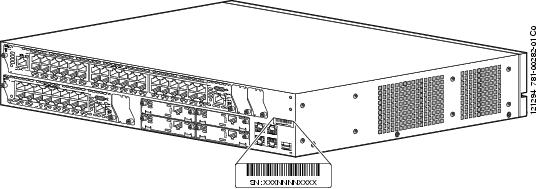
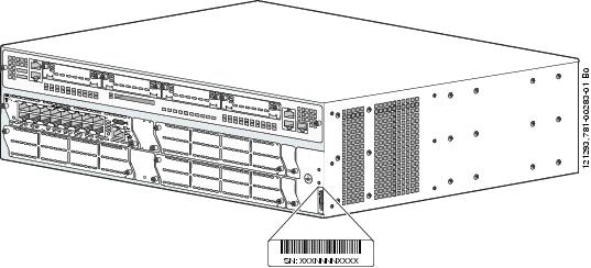
The serial number label for Cisco 3825 and Cisco 3845 routers is located on the rear of the chassis, on the right side, as shown in Figure 1 and Figure 2.
Figure 1 Serial Number Location on Cisco 3825 Routers
Figure 2 Serial Number Location on Cisco 3845 Routers
For detailed product serial number location on the chassis, see the online Cisco 3800 series hardware installation documentation at the following URL:
http://cisco.com/en/US/products/ps5855/prod_installation_guides_list.html
Cisco Product Identification Tool
The Cisco Product Identification tool provides detailed illustrations and descriptions showing where to locate serial number labels on Cisco products. It includes the following features:
•
•
•
The tool streamlines the process of locating serial number labels and identifying products. Serial number information expedites the entitlement process and is important for access to support services.
The Cisco Product Identification tool can be accessed at the following URL:
http://tools.cisco.com/Support/CPI/index.do
3 Documents, Equipment, and Tools
User Documentation
For complete platform documentation, see the following URL:
Step 1
All the documents referenced in this quick start guide are available on Cisco.com. See the "Where to Go Next" section. To view or print an online document in its original page format, click the PDF icon.
Translated Versions
http://cisco.com/en/US/docs/routers/access/3800/hardware/quick/guide/38qsgesp.pdf
http://cisco.com/en/US/docs/routers/access/3800/hardware/quick/guide/38qsgchs.pdf
Items Included with Cisco 3800 Series Routers
Your router package should include the following items in addition to the router:
•
•
•
•
•
•
•
•
•
Items Not Included
Individual items in this list may be required for your application:
•
•
•
•
•
•
•
4 Install Chassis
This section contains basic installation procedures. For more detailed installation instructions, see the Cisco 3800 series hardware installation documentation at the following URL:
http://cisco.com/en/US/products/ps5855/prod_installation_guides_list.html
Safety Information
For safety information you must know before working on your Cisco router, see the Cisco 2800 Series and Cisco 3800 Series Regulatory Compliance and Safety Information document that accompanied this device.
This document contains translations of the warnings that appear in this quick start guide.
Warning Definition
Warning
Warning
Warning
Warning
Warning
Warning
Warning
Warning
Warning
Installing the Router
You can install any Cisco 3800 series router in a rack. See the applicable instructions in the following sections.
Note
http://cisco.com/en/US/products/ps5855/prod_installation_guides_list.html
For module and interface card compatibility information, see the data sheet for each module and interface card.
Caution
Rack-Mounting the Router
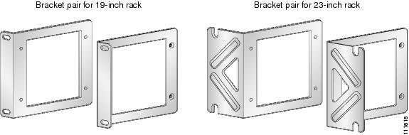
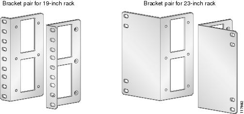
Cisco 3800 series routers can be installed in 19-inch (48.26-cm) racks. Use the standard brackets for mounting the chassis in a 19-inch (48.26-cm) rack.
Note
You can mount the router in the following ways:
•
•
•
The brackets are shown in Figure 3 and Figure 4.
Figure 3 Rack-Mounting Brackets for Cisco 3825 Routers
Figure 4 Rack-Mounting Brackets for Cisco 3845 Routers
Attaching Brackets to the Router for Rack-Mounting
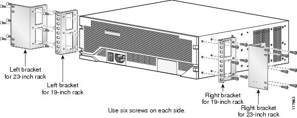
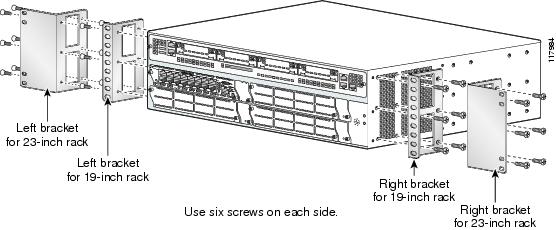
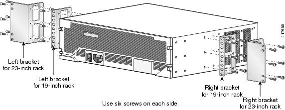
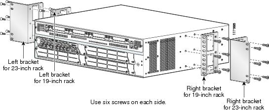
Attach the mounting brackets to the router chassis as shown in Figure 5 through Figure 8, using the screws provided.
Caution
Caution
Figure 5 Bracket Installation for Front Mounting
Figure 6 Bracket Installation for Rear Mounting
Figure 7 Bracket Installation for Center Mounting with Front Panel Forward
Figure 8 Bracket Installation for Center Mounting with Rear Panel Forward
Installing the Router in a Rack
Caution
Use two screws for each side (supplied with the rack, not with the router).
Tip
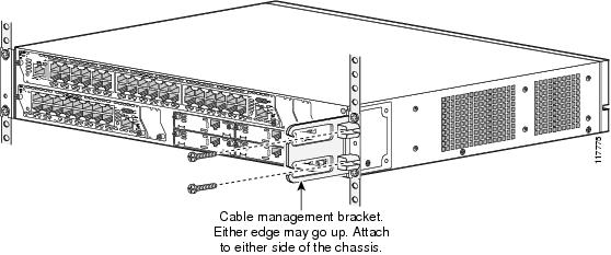
Attaching the Cable Management Bracket
The optional cable management bracket provides attachment points for organizing and routing cables. Attach the cable management bracket to the left or right rack-mount bracket using the screw provided. You can attach the cable management bracket to either the upper or the lower threaded hole. See Figure 9 for attachment locations.
Figure 9 Attaching the Cable Management Bracket to the Cisco 3825 Router
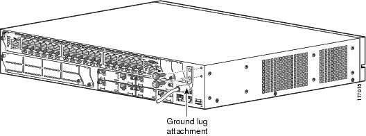
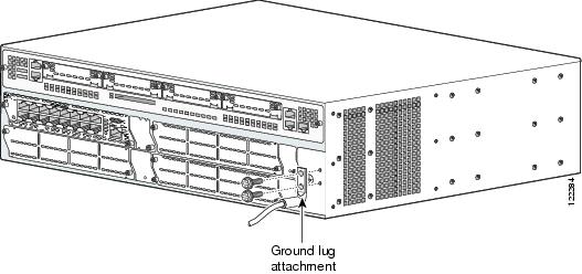
Grounding the Chassis
Warning
Warning
You must connect the chassis to a reliable earth ground; the ground wire must be installed in accordance with local electrical safety standards. For NEBS-compliant grounding, use size 6 AWG (13 mm2) copper wire and the ground lug provided in the accessory kit.
Note
To connect the chassis to a reliable earth ground, perform the following steps:
Step 1
Step 2
Step 3
Step 4
Figure 10 NEBS-Compliant Chassis Ground Connection on Cisco 3825 Chassis
Figure 11 NEBS-Compliant Chassis Ground Connection on Cisco 3845 Chassis
5 Connect Cables
Warning
Warning
Warning
Warning
Warning
Warning
Caution
Caution
Power Connections
This section describes procedures for connecting your router to AC power, DC power, and backup power. See the appropriate subsection:
•
•
•
Warning
Note
Connecting the Routers to AC Power
If your router uses AC power, connect it to a 15 A, 120 VAC (240 VAC, 10 A) circuit with overcurrent protection. If backup power is required, see the "Connecting the Router to Backup Power" section.
Note
Warning
Warning
The following warning applies to both AC power supplies and AC power supplies with IP phone power in the Cisco 3825 router and Cisco 3845 router:
Warning
120 VAC, 15 A (240 VAC, 10 A). Statement 1005
Note
Connecting the Router to DC Power
If your router has a DC-input power supply, follow the directions in this section for proper wiring. If backup power is required, see the "Connecting the Router to Backup Power" section.
DC Wiring Requirements for Cisco 3800 Series Routers
Caution
Warning
Warning
60 VDC, 20 A. Statement 1005
Warning
60 VDC, 30 A. Statement 1005
Note
Warning
A Cisco 3800 series router with a DC-input power supply requires copper wire for the power connections. Table 1 and Table 2 summarize the DC wiring requirements.
If you connect dual DC power sources to a Cisco 3825 router, both sources must be the same polarity and voltage.
For a Cisco 3845 router, the safety ground wire connection must be at the same potential as the 0 V (return) connection.
Table 1 DC Wiring Requirements for Cisco 3825 Routers
24-36 VDC, 12 A, positive or negative, single source or dual sources
AWG 14 (2.0 mm2)
AWG 14 (2.0 mm2), minimum
Amp/Type No. 32957 or equivalent
20 A maximum
36-60 VDC, 8 A, positive or negative, single source or dual sources
1 The input voltage tolerance limits for DC power are 18 and 72 VDC.
Table 2 DC Wiring Requirements for Cisco 3845 Routers
Wire Size
Wire Size24-36 V, 19 A, positive or negative, single source or dual sources
AWG 12
(3.0 mm2)AWG 12 (3.0 mm2), minimum
Amp/Tyco No. 34852 or equivalent
30 A
36-60 V, 13 A, positive or negative, single source or dual sources
AWG 12 or 14
(3.0 or 2.0 mm2)AWG 12 (3.0 mm2), minimum
For AWG 12: Amp/Tyco No. 34852 or equivalent
For AWG 14: Amp/Tyco No. 32957 or equivalent
20 - 30 A
1 The input voltage tolerance limits for DC power are 18 and 72 VDC.
Wiring Procedure for DC Input
To connect the router to a DC power source, perform the following steps:
Step 1
Warning
Tip
Warning
Step 2
Step 3
Step 4
Step 5
Warning
Warning
Caution
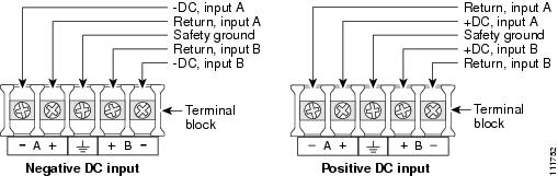
Figure 12 DC Power Connections for Cisco 3825 Routers (Typical)
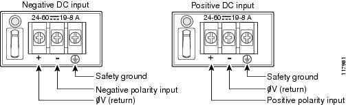
Figure 13 DC Power Connections for Cisco 3845 Routers
Step 6
Warning
Step 7
Step 8
Step 9
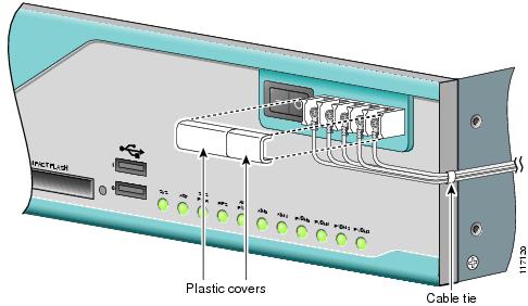
Figure 14 DC Wire Routing and Attachment for Cisco 3825 Routers
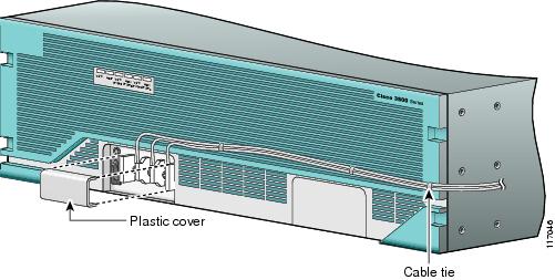
Figure 15 DC Wire Routing and Attachment for Cisco 3845 Routers
Approved Scenarios and Scenarios Not Approved for Dual DC Power Supply Configuration
You can connect a single DC power source to either the A input or the B input. If there are dual power sources, connect one source to the A input and one source to the B input. Both sources must be the same polarity (with respect to ground) and voltage (within 0.25 volts). Do not connect -DC grounded and +DC grounded dual sources to a Cisco 3825 series integrated router.
Caution
In Figure 16, either the positive source terminal or the negative source terminal is tied to ground.
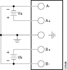
Figure 16 Connecting to One Source Only—Source A or Source B
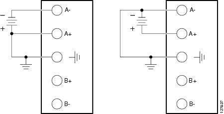
In Figure 17, source A and source B share common negative terminal connections.
Figure 17 Connecting Source A and Source B with Common Negative Terminals
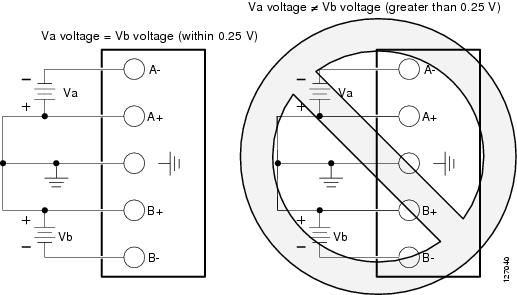
In Figure 18, source A and source B share common positive terminal connections. This is allowed only if Va equals Vb (within 0.25 V).
Caution
Note
Figure 18 Connecting Source A and Source B with Common Positive Terminals
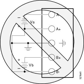
In Figure 19, source A and source B are wired with opposite polarity grounds. Do not use this configuration.
Figure 19 Source A and Source B Wired with Opposite-Polarity Grounds
Connecting the Router to Backup Power
The Cisco 3845 router operates in redundant mode when two power supplies are installed. The Cisco 3825 router has one internal power supply and a connector for mating to an external backup power source.
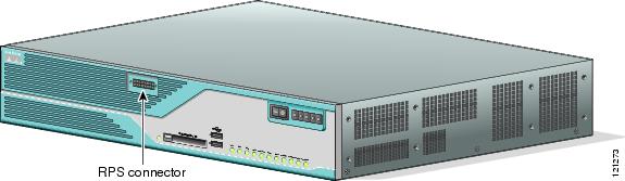
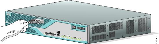
To connect the Cisco 3825 router to the external Cisco Redundant Power System (RPS), remove the RPS connector cover from the bezel and connect the RPS cable. (See Figure 20 and Figure 21.)
See the Cisco RPS-675 Hardware Installation Guide for more information about RPS power connections. To locate this documents, see the "Where to Go Next" section.
Note
http://cisco.com/en/US/products/ps5855/prod_installation_guides_list.html
Caution
Figure 20 RPS Connector on the Cisco 3825 Router
Figure 21 Plugging the RPS Connector into the Cisco 3825 Router
WAN, LAN, and Voice Connections
The connections and cables listed in Table 3 are described in detail in the Cisco 3800 series hardware installation documents at the following URL:
http://cisco.com/en/US/products/ps5855/prod_installation_guides_list.html
Note
Cisco Modular Access Router Cable Specifications document.Warning
Statement 1036
Warning
Warning
Caution
Table 3 summarizes some typical WAN, LAN, and voice connections for the Cisco 3800 series routers.
Table 3 WAN, LAN, and Voice Connections
Ethernet
RJ-45, yellow
Ethernet switch
Category 5 or higher Ethernet
T1/E1 WAN
xCE1T1-PRIRJ-48C/CA81A
RJ-48S, tanT1 or E1 network
External T1 CSU or other T1 equipmentRJ-48 T1/E1
RJ-48S to RJ-48S TE; RJ-48S to RJ-48S NT; RJ-48S to RJ-48S T1' RJ-48S to bare
RJ-48S to BNC; RJ-48S to twinaxial cable
RJ-48S to DB-15
RJ-48S to DB-15 nullT3/DS3/E3 WAN
BNC connector
T3 network, CSU/DSU, or other T3/DS3 equipment
75-ohm coaxial cable
OC3 / STM-1 WAN
SC connector
OC3/STM-1 network or device
Single-mode or multimode optical fiber
Cisco serial
60-pin D-sub, blue
CSU/DSU and serial network or equipment
Cisco serial transition cable that matches the signaling protocol (EIA/TIA-232, EIA/TIA-449, V.35, X.21, or EIA-530)
and the serial port operating mode (DTE or DCE).2Cisco Smart serial
Cisco Smart compact connector, blue
CSU/DSU and serial network or equipment
ADSL
RJ-11C/CA11A, lavender
Network demarcation device for service provider's DSL interface
RJ-11 straight-through
SHDSL
RJ-11C/CA11A, lavender, RJ-14
Network demarcation device for service provider's DSL interface
RJ-11 straight-through for 2-wire
RJ-14 straight-through for 4-wireT1/E1 digital voice
RJ-48C/CA81A, tan
Digital PBX, ISDN network, CSU/DSU
RJ-48 T1/E1
Analog voice FXS
RJ-11, gray
Telephone, fax
RJ-11; RJ21 if using NM-HDA, straight-through
Analog voice FXO
RJ-11, pink
Central office, analog PBX
Analog voice E&M
RJ-45, brown
Analog PBX
RJ-45
BRI S/T WAN
(external NT1)RJ-45/CB-1D, orange
NT1 device or private integrated network exchange (PINX)
RJ-45 straight-through
BRI U WAN
(built-in NT1)RJ-49C/CA-A11, red
ISDN network
RJ-48 straight-through
BRI NT/TE
(built-in NT1)RJ-45, orange
ISDN terminal equipment and ISDN network
RJ-45 straight-through in TE mode
BRI crossover in NT mode
56/64-kbps CSU/DSU
8-pin modular, blue
RJ-48S interface in subrate device or network
RJ-48 straight-through
T1/FT1 CSU/DSU
8-pin modular, blue
RJ-48C interface
RJ-48 straight-through
Gigabit Ethernet SFP, optical
LC, color according to optical wavelength
1000BASE-SX, -LX, -LH, -ZX, -CWDM
Optical fiber as specified on applicable data sheet
1 The color codes are specific to cables shipped by Cisco.
2 See the Cisco Modular Access Router Cable Specifications document for information about selecting these cables.
System Management Connections
The connections described in Table 4 provide system management access.
Note
6 Power Up the Router
Caution
Checklist for Power Up
You are ready to power up the Cisco 3800 series router after the following steps are completed:
•
•
•
•
•
•
Note
Power-Up Procedure
To power up your Cisco router and verify that it goes through its initialization and self-test, perform this procedure. When the procedure is finished, the Cisco router is ready to configure.
Note
Step 1
Step 2
http://cisco.com/en/US/products/ps5855/tsd_products_support_troubleshoot_and_alerts.html
Startup messages appear in your terminal emulation program window. After Cisco IOS software has finished booting, the SYS LED for both routers is steady green, and the SYS PWR1 LED or SYS PWR2 LED on the Cisco 3845 chassis is steady green.
Caution
Verify the Front Panel LED Indications
The indicator LEDs described in Table 5 provide power, activity, and status information:
Verify the Hardware Configuration
To display and verify the hardware features, enter the following commands:
•
•
7 Port Numbering
Each built-in networking port on a Cisco 3800 series router, and each port on a network module or interface card, is identified in Cisco IOS software by an interface type and a number or series of numbers separated by forward slashes (/). Port numbers for Cisco 3800 series routers follow the rules in this section.
Note
Built-In Ports
The Gigabit Ethernet ports built into the router's rear panel are numbered 0/0 and 0/1. These numbers are used with the interface-type keyword gigabitethernet to identify these ports in Cisco IOS software commands—gigabitethernet 0/0 and gigabitethernet 0/1.
Network Module Ports
Ports on network modules inserted into a router slot are numbered slot/port, where slot is the slot number and port is the port number.
The Cisco 3825 router has two network module slots. The lower slot is numbered 1; the upper slot is numbered 2. The
Cisco 3845 router has four slots: 1 at lower right, 2 at lower left, 3 at upper right, and 4 at upper left.
Note
Ports in a network module are normally numbered from right to left and bottom to top, starting at 0. See the Cisco Network Modules Hardware Installation Guide for more information.
Table 6 summarizes the interface numbering.
Table 6 Port Numbering
Built into the chassis rear panel
Interface-type 0 / port
interface gigabitethernet 0/1
In an interface card plugged directly into a chassis slot
Interface-type 0 / interface-card-slot2 / port
interface serial 0/1/1
In an interface card plugged into a slot in a network module
Interface-type network-module-slot3 / interface-card-slot / port
voice-port 1/1/0
Built into a network module
Interface-type network-module-slot / port
interface gigabitethernet 1/0
1 The interfaces listed are examples only; other possible interface types are not listed.
2 Interface card slot numbers for double-width interface-card slots are 1 and 3 only.
3 Network module slot numbers are 1 and 2 for the Cisco 3825 router; 1, 2, 3, and 4 for the Cisco 3845 router.
Interface Card Ports
Interface cards can be inserted either directly into a router slot or into a slot in a network module.
Interface Card in Router
Interface cards inserted into a router slot are numbered 0/HWIC-slot/port. HWIC-slot is 0, 1, 2, or 3, as labeled on the router rear panel.
Note
Ports in an interface card are normally numbered from right to left and bottom to top, starting at 0. See the Cisco Interface Cards Installation Guide for more information.
Interface Card in Network Module
Some network modules provide slots for interface cards. Ports in these interface cards are numbered router-slot/module-slot/port, where router-slot is 1, 2, 3, or 4.
Note
Slots in network modules for interface cards are normally numbered from right to left, starting at 0. Ports in an interface card are normally numbered from right to left and bottom to top, starting at 0. For more information, see the Cisco Network Modules Hardware Installation Guide and Cisco Interface Cards Installation Guide.
Note
8 Perform Initial Configuration
You can configure your router by using one of the following tools:
•
•
•
Note
Initial Configuration Using Cisco Router and Security Device Manager (SDM)
If the following messages appear at the end of the startup sequence, Cisco Router and Security Device Manager (SDM) is installed on your router:
yourname con0 is now availablePress RETURN to get started.For instructions on configuring your router by using SDM, see the Cisco Router and Security Device Manager (SDM) Quick Start Guide that shipped with your router.
Tip
http://www.cisco.com/pcgi-bin/tablebuild.pl/sdm
To obtain the SDM quick start guide, SDM release notes, and other SDM documentation, go to www.cisco.com/go/sdm and click the Technical Documentation link.
Initial Configuration Using the Setup Command Facility
This section shows how to use the setup command facility to configure a hostname for the router, set passwords, and configure an interface for communication with the management network. If the following messages appear at the end of the startup sequence, the setup command facility has been invoked automatically:
--- System Configuration Dialog ---At any point you may enter a question mark '?' for help.Use ctrl-c to abort configuration dialog at any prompt.Default settings are in square brackets '[]'.Would you like to enter the initial configuration dialog? [yes/no]:The setup command facility prompts you for basic information about your router and network, and it creates an initial configuration file. After the configuration file is created, you can use the CLI or Cisco Router and Security Device Manager (SDM) to perform additional configuration.
The prompts in the setup command facility vary depending on your router model, the installed interface modules, and the software image. The following example and the user entries (in bold) are shown as examples only.
For help with interface and port numbering, see the "Port Numbering" section.
Note
Step 1
Would you like to enter the initial configuration dialog? [yes/no]: yesStep 2
At any point you may enter a question mark '?' for help.Use ctrl-c to abort configuration dialog at any prompt.Default settings are in square brackets '[]'.Basic management setup configures only enough connectivityfor management of the system, extended setup will ask youto configure each interface on the systemWould you like to enter basic management setup? [yes/no]: yesStep 3
Configuring global parameters:Enter host name [Router]: RouterStep 4
The enable secret is a password used to protect access toprivileged EXEC and configuration modes. This password, afterentered, becomes encrypted in the configuration.Enter enable secret: xxxxxxStep 5
The enable password is used when you do not specify anenable secret password, with some older software versions, andsome boot images.Enter enable password: xxxxxxStep 6
The virtual terminal password is used to protectaccess to the router over a network interface.Enter virtual terminal password: xxxxxxStep 7
Configure SNMP Network Management? [yes]:Community string [public]:A summary of the available interfaces appears.
Note
Current interface summaryController Timeslots D-Channel Configurable modes StatusT1 0/0/0 24 23 pri/channelized Administratively upT1 0/0/1 24 23 pri/channelized Administratively upT1 0/2/0 24 23 pri/channelized Administratively upT1 0/2/1 24 23 pri/channelized Administratively upAny interface listed with OK? value "NO" does not have a valid configurationInterface IP-Address OK? Method Status ProtocolGigabitEthernet0/0 20.0.0.40 YES DHCP up upGigabitEthernet0/1 unassigned NO unset up upStep 8
Enter interface name used to connect to themanagement network from the above interface summary: gigabitethernet0/0Step 9
Configuring interface GigabitEthernet0/0:Use the 100 Base-TX (RJ-45) connector? [yes]: yesOperate in full-duplex mode? [no]: noConfigure IP on this interface? [yes]: yesIP address for this interface: 172.1.2.3Subnet mask for this interface [255.255.0.0] : 255.255.0.0Class B network is 172.1.0.0, 16 subnet bits; mask is /16The configuration is displayed:
The following configuration command script was created:hostname Routerenable secret 5 $1$D5P6$PYx41/lQIASK.HcSbfO5q1enable password xxxxxxline vty 0 4password xxxxxxsnmp-server community public!no ip routing!interface GigabitEthernet0/0no shutdownmedia-type 100BaseXhalf-duplexip address 172.1.2.3 255.255.0.0!interface GigabitEthernet0/1shutdownno ip address!endStep 10
[0] Go to the IOS command prompt without saving this config.[1] Return back to the setup without saving this config.[2] Save this configuration to nvram and exit.Enter your selection [2]: 2Building configuration...Use the enabled mode 'configure' command to modify this configuration.Press RETURN to get started! RETURNThe user prompt appears:
Router>Step 11
Initial Configuration Using the Cisco CLI—Manual Configuration
This section shows how to display a command-line interface (CLI) prompt for configuration using the CLI, and it directs you to documentation for the CLI configuration. You can use the CLI if the following messages appear at the end of the startup sequence:
--- System Configuration Dialog ---At any point you may enter a question mark '?' for help.Use ctrl-c to abort configuration dialog at any prompt.Default settings are in square brackets '[]'.Would you like to enter the initial configuration dialog? [yes/no]:If these messages do not appear, SDM and a default configuration file were installed on the router at the factory. To use SDM to configure the router, see the "Initial Configuration Using Cisco Router and Security Device Manager (SDM)" section.
For help with interface and port numbering, see the "Port Numbering" section.
Step 1
Would you like to enter the initial configuration dialog? [yes/no]: noStep 2
Would you like to terminate autoinstall? [yes] ReturnSeveral messages appear, ending with a line similar to the following:
...Copyright (c) 1986-2004 by Cisco Systems, Inc.Compiled <date> <time> by <person>Step 3
...flashfs[4]: Initialization complete.Router>Step 4
Router> enableRouter#Step 5
http://cisco.com/en/US/products/ps5855/tsd_products_support_configure.html
Note
Step 6
Verify the Initial Configuration
Verify that the new interfaces are operating correctly by performing the following tests:
•
•
•
When you complete and verify the initial configuration, your Cisco router is ready to configure for specific functions. See the "Where to Go Next" section for information about locating documentation for advanced configuration procedures.
9 Where to Go Next
For additional configuration procedures, see the appropriate Cisco 3800 series routers documentation or Cisco IOS software documentation, available online on Cisco.com.
Tip
To access documentation on Cisco.com:
For Cisco 3800 series routers platform documentation, start on Cisco.com at http://www.cisco.com, and choose Products & Solutions > Routers > Cisco 3800 Series Integrated Services Routers > Technical Documentation > Document type > Document.
For Cisco IOS software documentation, start on Cisco.com at http://www.cisco.com, and choose Products & Solutions > IOS Software > Cisco IOS Software Releases > Your Cisco IOS software release.
To get updated information about platform support for features, access Cisco Feature Navigator II at http://www.cisco.com/go/fn. (This requires a registered account on Cisco.com.)
To access documentation using Cisco Connection Online (CCO):
For Cisco 3800 series routers platform documentation, start on Cisco.com at http://www.cisco.com, and click the Technical Documentation link under Quick Links. Under the Product Documentation heading, navigate to Modular Access Routers and to the documentation for your router.
For Cisco IOS software documentation, start on Cisco.com at http://www.cisco.com, and click the Technical Documentation link under Quick Links. Under the Product Documentation heading, navigate to the Cisco IOS software documentation for the Cisco IOS software release that is installed on your router.
10 Obtaining Documentation
For information on obtaining documentation, submitting a service request, and gathering additional information, see the monthly What's New in Cisco Product Documentation, which also lists all new and revised Cisco technical documentation, at:
http://www.cisco.com/en/US/docs/general/whatsnew/whatsnew.html
11 Documentation Feedback
You can send comments about technical documentation to bug-doc@cisco.com.
You can submit comments by using the response card (if present) behind the front cover of your document or by writing to the following address:
Cisco Systems
Attn: Customer Document Ordering
170 West Tasman Drive
San Jose, CA 95134-9883We appreciate your comments.
12 Obtaining Technical Assistance
For all customers, partners, resellers, and distributors who hold valid Cisco service contracts, Cisco Technical Support provides 24-hour-a-day, award-winning technical assistance. The Cisco Technical Support Website on Cisco.com features extensive online support resources. In addition, Cisco Technical Assistance Center (TAC) engineers provide telephone support. If you do not hold a valid Cisco service contract, contact your reseller.
Cisco Technical Support Website
The Cisco Technical Support Website provides online documents and tools for troubleshooting and resolving technical issues with Cisco products and technologies. The website is available 24 hours a day, 365 days a year, at this URL:
http://www.cisco.com/techsupport
Access to all tools on the Cisco Technical Support Website requires a Cisco.com user ID and password. If you have a valid service contract but do not have a user ID or password, you can register at this URL:
http://tools.cisco.com/RPF/register/register.do
Note
Submitting a Service Request
Using the online TAC Service Request Tool is the fastest way to open S3 and S4 service requests. (S3 and S4 service requests are those in which your network is minimally impaired or for which you require product information.) After you describe your situation, the TAC Service Request Tool provides recommended solutions. If your issue is not resolved using the recommended resources, your service request is assigned to a Cisco TAC engineer. The TAC Service Request Tool is located at this URL:
http://www.cisco.com/techsupport/servicerequest
For S1 or S2 service requests or if you do not have Internet access, contact the Cisco TAC by telephone. (S1 or S2 service requests are those in which your production network is down or severely degraded.) Cisco TAC engineers are assigned immediately to S1 and S2 service requests to help keep your business operations running smoothly.
To open a service request by telephone, use one of the following numbers:
Asia-Pacific: +61 2 8446 7411 (Australia: 1 800 805 227)
EMEA: +32 2 704 55 55
USA: 1 800 553-2447For a complete list of Cisco TAC contacts, go to this URL:
http://www.cisco.com/techsupport/contacts
Definitions of Service Request Severity
To ensure that all service requests are reported in a standard format, Cisco has established severity definitions.
Severity 1 (S1)—Your network is "down," or there is a critical impact to your business operations. You and Cisco will commit all necessary resources around the clock to resolve the situation.
Severity 2 (S2)—Operation of an existing network is severely degraded, or significant aspects of your business operation are negatively affected by inadequate performance of Cisco products. You and Cisco will commit full-time resources during normal business hours to resolve the situation.
Severity 3 (S3)—Operational performance of your network is impaired, but most business operations remain functional. You and Cisco will commit resources during normal business hours to restore service to satisfactory levels.
Severity 4 (S4)—You require information or assistance with Cisco product capabilities, installation, or configuration. There is little or no effect on your business operations.
13 Obtaining Additional Publications and Information
For information on obtaining documentation, submitting a service request, and gathering additional information, see the monthly What's New in Cisco Product Documentation, which also lists all new and revised Cisco technical documentation, at:
http://www.cisco.com/en/US/docs/general/whatsnew/whatsnew.html
DOC-7816391=