Any Transport over MPLS (AToM)
MPLS AToM: Configuring

Table Of Contents

MPLS AToM — Configuring

Documentation Specifics

Prerequisites to Configuring

Configuration Tasks

Step 1: Specify the Label Distribution Protocol

Step 2: Assign LDP Router IDs to the PE Routers

Step 3: Enable the PE Routers to Transport AToM Packets

Enable PE Routers to Transport ATM AAL5 SDUs and ATM Cell Relay Packets

Enable PE Routers to Transport Ethernet Packets

Enable PE Routers with DLCI-to-DLCI Connections to Transport Frame Relay Packets

Enable PE Routers to Transport Frame Relay with Port-to-Port Connections, HDLC over MPLS, and PPP over MPLS Packets

Enable Other PE Devices to Transport Frame Relay Packets

Step 4: Configure the Customer CE Routers

Configure CE Routers for ATM AAL5 over MPLS

Configure CE Routers for ATM Cell Relay over MPLS

Configure CE Routers for Ethernet over MPLS

Configure CE Routers for Frame Relay over MPLS

Configure CE Routers for HDLC over MPLS

Configure CE Routers for PPP over MPLS

Verification Tasks

Verify Connectivity Between the PE Routers

Verify Connectivity Between the P and PE Routers

Verify Connectivity Between the PE and CE Routers

Other Configuration Tasks

Configuring Quality of Service

Using CLP Bits to Determine the Experimental Bit Settings

Enabling OAM Cell Emulation for ATM AAL5 over MPLS

Specify the Rate at Which AIS Cells Are Sent

Troubleshooting Tasks

Estimating the Size of Packets Traveling Through the Core Network

Example of Estimating Packet Size

Changing the MTU Size on the P and PE Routers

Configuration Examples

ATM AAL5 over MPLS Configuration Example

ATM Cell Relay over MPLS Configuration Example

Ethernet over MPLS Configuration Example

Frame Relay over MPLS Configuration Example

HDLC over MPLS Configuration Example

PPP over MPLS Configuration Example

What To Do Next


MPLS AToM — Configuring


This document provides configuration tasks for the MPLS AToM and includes the following sections:

Documentation Specifics

Prerequisites to Configuring

Configuration Tasks

Verification Tasks

Other Configuration Tasks

Troubleshooting Tasks

Configuration Examples

What To Do Next

Documentation Specifics

This documentation set includes the following sections:

Start Here: MPLS AToM: Transport, Platform, and Release Specifics

MPLS AToM: Overview

MPLS AToM: Configuring (this document)

MPLS AToM: Commands


Note Start Here: MPLS AToM: Transport, Platform, and Release Specifics details the features that are supported in each release and on each platform. Not all MPLS AToM features are supported in each Cisco IOS software release for each platform. Read the entire chapter before reading the other chapters.

The other chapters provide overview, configuration, and command reference information for MPLS AToM features.


Prerequisites to Configuring

Before configuring AToM, configure the following:

Provide label switched paths (LSPs) between provider edge (PE) routers by enabling dynamic MPLS labeling (through the mpls ip command) on all paths between the imposition and disposition PE routers.

Enable and configure Cisco Express Forwarding (CEF) or distributed CEF before configuring ATM AAL5, ATM Cell Relay, or Ethernet over MPLS. Enable and configure CEF before configuring Frame Relay, HDLC, or PPP over MPLS.

Configuration Tasks

Perform the following configuration tasks to enable AToM:

Step 1: Specify the Label Distribution Protocol (required)

Step 2: Assign LDP Router IDs to the PE Routers (required)

Step 3: Enable the PE Routers to Transport AToM Packets (required)

Step 4: Configure the Customer CE Routers (optional)

Step 1: Specify the Label Distribution Protocol

To specify the label distribution protocol for this interface, issue the following command. If you do not specify LDP, tag distribution protocol (TDP) is used instead.

Router(config)# mpls label protocol ldp

Step 2: Assign LDP Router IDs to the PE Routers

To assign LDP router IDs to the PE routers, perform the following steps. Both PE routers require a loopback address that you can use to create a virtual circuit (VC) between the routers.


Step 1 Enter interface configuration mode by using the following command:

Router(config)# interface loopback0


Step 2 Assign an IP address to the loopback interface. The LDP router ID must be configured with a 32-bit mask to ensure proper operation of MPLS forwarding between PE routers.

Router(config-if)# ip address ip-address


Step 3 Force the loopback IP address to be used as the router ID. You must assign an LDP router ID to each PE router. The mpls ldp router-id command allows you to specify which interface's IP address to use as the router ID. The force keyword guarantees that the PE routers are correctly targeting the appropriate router ID. If you do not use the force keyword, the router might assign a different router ID, which can prevent the establishment of VCs between PE routers.

Router(config)# mpls ldp router-id loopback0 force


Step 3: Enable the PE Routers to Transport AToM Packets

In general, the steps for configuring a PE router so that it can transport Layer 2 packets include:


Step 1 Choose which interface will transport the packets with the interface command.

Step 2 Specify the type of encapsulation you want on the interface with the encapsulation command.

Step 3 Enable the local and remote PE router to establish a virtual circuit with the mpls l2transport route command. On each PE router, specify the loopback address of the remote PE router at the other end of the VC. You also assign a number to the VC, called a VC ID. Specify the same VC ID on both ends of the VC. On a PE router, the destination and vc-id pair must be unique. See the mpls l2transport route command for more information.


Each transport type might require some additional commands, which are detailed in the following sections:

Enable PE Routers to Transport ATM AAL5 SDUs and ATM Cell Relay Packets

Enable PE Routers to Transport Ethernet Packets

Enable PE Routers with DLCI-to-DLCI Connections to Transport Frame Relay Packets

Enable PE Routers to Transport Frame Relay with Port-to-Port Connections, HDLC over MPLS, and PPP over MPLS Packets

Enable Other PE Devices to Transport Frame Relay Packets

Enable PE Routers to Transport ATM AAL5 SDUs and ATM Cell Relay Packets

In this release, the ATM Cell Relay features transports only a single cell. You must configure ATM Cell Relay on the permanent virtual circuits. ATM Cell Relay over MPLS supports only PVC mode, single cell relay.

 
Command
Purpose

Step 1 

Router(config)# interface atmx/x

Specifies an ATM interface.

Step 2 

Router(config-atm-vc)# pvc vpi/vci l2transport

Assigns a virtual path identifier (VPI) and virtual circuit identifier (VCI). The l2transport keyword indicates that the PVC is a switched PVC instead of a terminated PVC.

You can configure ATM AAL5 and ATM Cell Relay over MPLS on permanent virtual circuits (PVCs) only. You cannot configure AAL5 over MPLS on main interfaces.

Step 3 

For ATM AAL5:

Router(config-atm-vc)# encapsulation aal5


For ATM Cell Relay:

Router(config-atm-vc)# encapsulation aal0

For ATM AAL5, this command specifies ATM AAL5 encapsulation for the interface.

For ATM Cell Relay, this command specifies raw cell encapsulation for the interface.

Make sure you specify the same encapsulation type on the PE and CE routers.

Step 4 

Router(config-atm-vc)# mpls l2transport route destination vc-id

Creates the VC to transport the Layer 2 packets.

Enable PE Routers to Transport Ethernet Packets


Note You must configure Ethernet over MPLS on the subinterfaces.


Command
Purpose

Step 1 

Router(config-if)# interface GigabitEthernetx/x.x

Specifies the GigabitEthernet subinterface. Make sure the subinterface on the adjoining CE router is on the same VLAN as this PE router.

Step 2 

Router(config-subif)# encapsulation dot1q vlan-id

Enables the subinterface to accept 802.1Q VLAN packets.

The interfaces/subinterfaces between the CE and PE routers that are running Ethernet over MPLS must be in the same VLAN and subnet. All other interfaces/subinterfaces and backbone routers do not.

Step 3 

Router(config-subif)# mpls l2transport route destination vc-id

Creates the VC to transport the VLAN packets.

Enable PE Routers with DLCI-to-DLCI Connections to Transport Frame Relay Packets

 
Command
Purpose

Step 1 

Router(config)# frame-relay switching

Enable permanent virtual circuit (PVC) switching on a Frame Relay device.

Step 2 

Router(config)# interface Serialx/x

Specifies a serial interface.

Step 3 

Router(config-if)# encapsulation frame-relay frame-relay-type

Specifies Frame Relay encapsulation for the interface. You can specify different types of encapsulations. You can set one interface to Cisco encapsulation and the other interface to IETF encapsulation.

Step 4 

Router(config-if)# frame-relay intf-type dce

Specifies that the interface is a DCE switch. You can also specify the interface to support NNI and DTE connections.

Step 5 

Router(config)# connect connection-name interface dlci l2transport

Defines connections between Frame Relay PVCs. Using the l2transport keyword specifies that the PVC will not be a locally switched PVC, but will be tunneled over the backbone network.

The argument connection-name is a text string that you provide.

The argument interface is the interface on which a PVC connection will be defined.

The argument dlci is the data-link connection identifier (DLCI) number of the PVC that will be connected.

Step 6 

Router(config-fr-pw-switching)# mpls l2transport route destination vc-id

Creates the VC to transport the Layer 2 packets. In a DLCI-to DLCI connection type, Frame Relay over MPLS uses the mpls l2transport route command in connect submode.

Enable PE Routers to Transport Frame Relay with Port-to-Port Connections, HDLC over MPLS, and PPP over MPLS Packets

Use the following steps to set up any of the following transport types:

Frame Relay Port-to-Port: When you set up a port-to-port connection between PE routers, you use HDLC mode to transport the Frame Relay encapsulated packets.

HDLC

PPP

 
Command
Purpose

Step 1 

Router(config)# interface Serialx/x

Specifies a serial interface.

You must configure HDLC and PPP over MPLS on router interfaces only. You cannot configure HDLC over MPLS on subinterfaces.

Step 2 

For Frame Relay Port-to-Port or HDLC encapsulation:

Router(config-if)# encapsulation hdlc


For PPP encapsulation:

Router(config-if)# encapsulation ppp

For Frame Relay port-to-port encapsulation, this command transports Frame Relay packets in an HDLC packet.

Otherwise, the packet is encapsulation as an HDLC or PPP packet.

Step 3 

Router(config-fr-pw-switching)# mpls l2transport route destination vc-id

Creates the VC to transport the Layer 2 packets.

Enable Other PE Devices to Transport Frame Relay Packets

You can configure an interface as a DTE device or a DCE switch, or as a switch connected to a switch with NNI connections. Use the following command in interface configuration mode:

frame-relay intf-type [dce | dte | nni]

The keywords are explained in the following table:

Keyword
Description

dce

Enables the router or access server to function as a switch connected to a router.

dte

Enables the router or access server to function as a DTE device. DTE is the default.

nni

Enables the router or access server to function as a switch connected to a switch.


Step 4: Configure the Customer CE Routers

This section explains how to configure the customer CE router to transport Layer 2 packets. If the customer CE routers are configured to accept Layer 2 packets, these steps are not necessary.

In general, you use the following steps to configure the CE router. Each transport type might require some additional commands, which are detailed in the following sections.

 
Command
Purpose

Step 1 

Router(config)# interface interface

Specifies an interface.

Step 2 

Router(config-atm-vc)# encapsulation encapsulation type

Specifies encapsulation for the interface.

Configure CE Routers for ATM AAL5 over MPLS

To configure the CE routers for ATM AAL5 over MPLS, make sure you specify the same encapsulation type on the PE and CE routers.

Router(config)# interface atmx/x
Router(config-if)# pvc vpi/vci
Router(config-atm-vc)# encapsulation aal5 

Note CE devices can also be switches.


Configure CE Routers for ATM Cell Relay over MPLS

To configure the CE routers for ATM Cell Relay over MPLS, make sure the CE routers have the same encapsulation type. However, the PE and CE routers can have different encapsulation types.

Router(config)# interface atmx/x
Router(config-if)# pvc vpi/vci
Router(config-atm-vc)# encapsulation aal5

Note CE devices can also be switches.


Configure CE Routers for Ethernet over MPLS

To configure the CE routers for Ethernet over MPLS, make sure the interfaces/subinterfaces on the CE routers connected to the PE routers share the same VLAN ID and are in the same subnet.

Router(config-if)# interface GigabitEthernet x/x.x
Router(config-subif)# encapsulation dot1Q vlan-id
Router(config-subif)# ip address ip-address

Configure CE Routers for Frame Relay over MPLS

To configure the CE routers for Frame Relay over MPLS, make sure the following conditions are met:

For DLCI-to-DLCI connections, the interfaces between the CE and PE routers must use the same LMI type. The CE routers must use the same encapsulation type.

For port-to-port connections, all the routers (PE and CE) must have the same type of LMI, encapsulation, and interface. The CE routers must be configured as either DCE-DTE or NNI-NNI.

In this procedure, the CE device is a router. The CE device can also be a Frame Relay switch.

The following example configures the CE routers for Frame Relay.

Router(config)# interface Serialx/x
Router(config-if)# encapsulation frame-relay [ietf]

Configure CE Routers for HDLC over MPLS

To configure the CE routers for HDLC over MPLS, if you configure keep-alive functionality, make sure that both CE router interfaces have keep-alives enabled with similar settings.

Router(config)# interface Serialx/x
Router(config-if)# encapsulation hdlc 
Router(config-if)# ip address ip-address


Note HDLC is the default encapsulation, so you do not have to enter the encapsulation command.


Configure CE Routers for PPP over MPLS

To configure the CE routers for PPP over MPLS, make sure the connections between the CE and PE routers on both ends of the backbone have similar link layer characteristics. The connections between the CE and PE routers must both be asynchronous or synchronous.

Router(config)# interface Serialx/x
Router(config-if)# encapsulation ppp
Router(config-if)# ip address ip-address 

Verification Tasks

Perform the following tasks to verify that AToM is properly configured on the network:

Verify Connectivity Between the PE Routers

Verify Connectivity Between the P and PE Routers

Verify Connectivity Between the PE and CE Routers

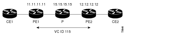
The following sections show the commands that help to verify the configuration of AToM. The verification procedures are based on the topology used in Figure 8.

Figure 8 Configuration Used for Verification

Verify Connectivity Between the PE Routers

Use the following commands on each PE router to ensure that the PE routers are working properly:


Step 1 To make sure the PE router endpoints have discovered each other, use the show mpls ldp discovery command. The command output shows that PE1 established a targeted LDP session with PE2.

PE1# show mpls ldp discovery 

Local LDP Identifier:
    11.11.11.11:0
Discovery Sources:
    Interfaces:
        POS6/0 (ldp): xmit/recv
            LDP Id: 15.15.15.15:0
    Targeted Hellos:
        11.11.11.11 -> 12.12.12.12 (ldp): active, xmit/recv
            LDP Id: 12.12.12.12:0

Step 2 Use the show mpls l2transport vc command to check that a VC (with VC ID 115) has been established between the PE routers and that the VC is operational.

PE1# show mpls l2transport vc

Local intf     Local circuit      Dest address    VC ID      Status
-------------  ------------------ --------------- ---------- ----------
AT1/0          ATM AAL5 0/115     12.12.12.12     115        UP

Step 3 To make sure the label distribution session has been established, use the show mpls ldp neighbors command. The output shows that:

PE1 and PE2 have established a targeted LDP session.

The LDP session is operational.

Messages are being sent and received.

PE1# show mpls ldp neighbor

Peer LDP Ident: 15.15.15.15:0; Local LDP Ident 11.11.11.11:0
        TCP connection: 15.15.15.15.11072 - 11.11.11.11.646
        State: Oper; Msgs sent/rcvd: 65/73; Downstream
        Up time: 00:43:02
        LDP discovery sources:
          POS6/0, Src IP addr: 30.5.0.2
        Addresses bound to peer LDP Ident:
          8.0.5.4         180.3.0.3       15.15.15.15     30.5.0.2
          30.5.0.3
Peer LDP Ident: 12.12.12.12:0; Local LDP Ident 11.11.11.11:0
        TCP connection: 12.12.12.12.11000 - 11.11.11.11.646
        State: Oper; Msgs sent/rcvd: 26/25; Downstream
        Up time: 00:10:35
        LDP discovery sources:
          Targeted Hello 11.11.11.11 -> 12.12.12.12, active
        Addresses bound to peer LDP Ident:
          8.0.6.3         12.12.12.12     30.5.0.4

Step 4 To make sure the label forwarding table is built correctly, use the show mpls forwarding-table command. The output shows the following data:

Local tag—Label assigned by this router.

Outgoing tag or VC—Label assigned by next hop, or VPI/VCI used to get to next hop.

Prefix or Tunnel Id—Address or tunnel to which AAL5 PDUs with this label are going.

Bytes tag switched— Number of bytes switched with this incoming label.

Outgoing interface—Interface through which AAL5 PDUs with this label are sent.

Next Hop—IP address of neighbor that assigned the outgoing label.

PE1# show mpls forwarding-table

Local  Outgoing    Prefix            Bytes tag  Outgoing   Next Hop
tag    tag or VC   or Tunnel Id      switched   interface
16     16          12.12.12.12/32    0          PO6/0      point2point
17     Pop tag     15.15.15.15/32    0          PO6/0      point2point
28     Untagged    l2ckt(115)        1120       AT1/0      point2point


Verify Connectivity Between the P and PE Routers

Use the following commands to ensure that the P router is correctly configured:


Step 1 Use the show mpls ldp discovery command to ensure that an LDP session exists. The command output shows that the P router has regular LDP sessions with the PE routers, not targeted LDP sessions.

P# show mpls ldp discovery 

Local LDP Identifier:
    15.15.15.15:0
    Discovery Sources:
    Interfaces:
        POS3/0 (ldp): xmit/recv
            LDP Id: 11.11.11.11:0
        POS6/0 (ldp): xmit/recv
            LDP Id: 12.12.12.12:0
    Targeted Hellos:
        15.15.15.15 -> 11.11.11.11 (ldp): active, xmit

Step 2 To make sure the label distribution session has been established, use the show mpls ldp neighbors command. The output shows that:

The P router has LDP sessions with PE1 and PE2.

The LDP session is operational.

Messages are being sent and received.


P# show mpls ldp neighbors

Peer LDP Ident: 11.11.11.11:0; Local LDP Ident 15.15.15.15:0
        TCP connection: 11.11.11.11.646 - 15.15.15.15.11072
        State: Oper; Msgs sent/rcvd: 80/71; Downstream
        Up time: 00:48:50
        LDP discovery sources:
          POS3/0, Src IP addr: 30.5.0.1
        Addresses bound to peer LDP Ident:
          8.0.5.20        11.11.11.11     180.3.0.2       20.20.20.3
          200.200.200.5   30.5.0.1
    Peer LDP Ident: 12.12.12.12:0; Local LDP Ident 15.15.15.15:0
        TCP connection: 12.12.12.12.646 - 15.15.15.15.11169
        State: Oper; Msgs sent/rcvd: 29/27; Downstream
        Up time: 00:16:28
        LDP discovery sources:
          POS6/0, Src IP addr: 30.5.0.4
        Addresses bound to peer LDP Ident:
          8.0.6.3         12.12.12.12     30.5.0.4

Step 3 To make sure the label forwarding table is built correctly, use the show mpls forwarding-table command.

P# show mpls forwarding-table

Local  Outgoing    Prefix            Bytes tag  Outgoing   Next Hop
tag    tag or VC   or Tunnel Id      switched   interface
16     Pop tag     12.12.12.12/32    18030      PO6/0      point2point
19     Pop tag     11.11.11.11/32    18609      PO3/0      point2point


Verify Connectivity Between the PE and CE Routers

ATM AAL5 and ATM Cell Relay

Use the show atm vc command on CE1 and CE2 to ensure that the ATM AAL5 VC is active.

CE# show atm vc 

           VCD /                                        Peak  Avg/Min Burst
Interface  Name         VPI   VCI  Type   Encaps   SC   Kbps   Kbps Cells  Sts
2/0/0.3    11           0     115  PVC    AAL5     UBR  149760              UP

Ethernet over MPLS

Issue the show ip interface brief command on the CE routers. If the interface can provide two-way communication, the Protocol field is marked "up." If the interface hardware is usable, the Status field is marked "up."

Router# show ip interface brief 

Interface                  IP-Address      OK? Method Status                Protocol
Vlan2                      10.1.2.58       YES NVRAM  up                    up      
Vlan4                      unassigned      YES NVRAM  up                    up      
Vlan101                    unassigned      YES NVRAM  up                    up      
GigabitEthernet6/0         172.31.255.255  YES NVRAM  administratively down down    
GigabitEthernet1/0         unassigned      YES NVRAM  administratively down down    
GigabitEthernet3/0         172.31.255.255  YES NVRAM  up                    up      
GigabitEthernet4/0         unassigned      YES NVRAM  administratively down down    
Loopback0                  172.16.0.0      YES NVRAM  up 

Frame Relay over MPLS

Use the show frame-relay pvc command on CE1 and CE2 to ensure that the DLCI is active. The line in the middle of the command output shows that DLCI 1002 is active.

CE1# show frame-relay pvc

PVC Statistics for interface POS2/1/0 (Frame Relay DTE)

              Active     Inactive      Deleted       Static
  Local          1            0            0            0
  Switched       0            0            0            0
  Unused         0            0            0            0

DLCI = 1002, DLCI USAGE = LOCAL, PVC STATUS = ACTIVE, INTERFACE = POS2/1/0.2      

input pkts 31           output pkts 29      in bytes 6555 
out bytes 6194          dropped pkts 0      in FECN pkts 0 
in BECN pkts 0          out FECN pkts 0     out BECN pkts 0 
in DE pkts 0            out DE pkts 0
out bcast pkts 14       out bcast bytes 4634 
pvc create time 00:16:43, last time pvc status changed 00:13:54

HDLC and PPP over MPLS

Use the show ip interface brief command on CE1 and CE2 to make sure the router interfaces are operating.

CE1# show ip interface brief

Interface                  IP-Address      OK? Method Status                Protocol
Serial1/1                  11.11.11.11     YES unset  up                    up
Serial2/1                  12.12.12.12     YES unset  up                    up
Hssi1/1                    10.10.10.10     YES unset  up                    up

Other Configuration Tasks

This section explains how to configure features that are not part of the basic AToM configuration. This section includes the following topics:

Configuring Quality of Service

Enabling OAM Cell Emulation for ATM AAL5 over MPLS

Configuring Quality of Service

To support QoS from PE to PE, you set the experimental bits in both the VC label and the LSP tunnel label. You set the experimental bits in the VC label, because the LSP tunnel label is removed at the penultimate router.

Notes:

QoS is not supported with ATM Cell Relay over MPLS.

On the Cisco 7500 series routers, enable dCEF before setting the experimental bits.

Use CEF mode when setting the experimental bits with AAL5 over MPLS.

See the "AToM and Quality of Service" section for more information about using QoS with the transports and platforms.

Use the following configuration steps to set the experimental bits.

 
Command
Purpose

Step 1 

Router(config)# class-map 
class-map-name 

Specifies the user-defined name of the traffic class.

Step 2 

Router(config-cmap)# match 
any

Specifies that all packets will be matched. In this release, use only the any keyword. Other keywords might cause unexpected results.

Step 3 

Router(config-cmap)# 
policy-map policy-name 

Specifies the name of the traffic policy to configure.

Step 4 

Router(config-pmap)# class 
class-map-name 

Specifies the name of a predefined traffic class, which was configured with the class-map command, used to classify traffic to the traffic policy.

Step 5 

Router (config-pmap-c)# set 
mpls experimental value

Designates the value to which the MPLS bits are set if the packets match the specified policy map.

Step 6 

Router(config)# interface 
interface-number 

Enters the interface.

Step 7 

Router(config-if)# 
service-policy input 
policy-name 

Attaches a traffic policy to an interface.

Displaying the Traffic Policy Assigned to an Interface

To display the traffic policy attached to an interface, use the show policy-map interface command.

Using CLP Bits to Determine the Experimental Bit Settings

The following configuration steps let you configure class maps and policy maps to control the setting of the EXP bit based on the CLP bit setting. This procedure applies to ATM AAL5 over MPLS.

 
Command
Purpose

Step 1 

Router(config)# class-map match any 
no-class

Specifies the user-defined name of the traffic class. The match any portion of the command allows a packet to be classified as a member of the traffic class called no-class if it matches any of the criteria in the following match command.

Step 2 

Router(config)# class-map match any 
yes-class

Specifies the user-defined name of the traffic class. The match any portion of the command allows a packet to be classified as a member of the traffic class called yes-class if it matches any of the criteria in the following match command.

Step 3 

Router(config-cmap)# policy-map 
atm-clp-policy

Specifies the name of the traffic policy to configure.

Step 4 

Router(config-pmap)# class no-class

Specifies the name of a predefined traffic class, which was configured with the class-map command, used to classify traffic to the traffic policy.

Step 5 

Router(config-pmap-c)# set mpls 
experimental 2

Designates the value to which the MPLS bits are set if the packets match the specified policy map.

Step 6 

Router(config-pmap)# class yes-class

Specifies the name of a predefined traffic class, which was configured with the class-map command, used to classify traffic to the traffic policy.

Step 7 

Router(config-pmap-c)# set mpls 
experimental 3

Designates the value to which the MPLS bits are set if the packets match the specified policy map.

Step 8 

Router(config)# interface interface-number 

Enters the interface.

Step 9 

Router(config-if)# service-policy input 
policy-name 

Attaches a traffic policy to an interface.

Enabling OAM Cell Emulation for ATM AAL5 over MPLS

To enable OAM cell emulation on the PE routers, issue the oam-ac emulation-enable command in AToM VC configuration mode. The following example shows how to enable OAM cell emulation on an ATM PVC.

Router# interface ATM 1/0/0

Router(config-if)# pvc 1/200 l2transport

Router(config-atm-vc)# oam-ac emulation-enable

Specify the Rate at Which AIS Cells Are Sent

The oam-ac emulation-enable command lets you specify the rate at which AIS cells are sent. The default is one cell every second. The range is 0 to 60 seconds. The following example sets the rate at which an AIS cell is sent to every 30 seconds:

Router(config-atm-vc)# oam-ac emulation-enable 30

See the oam-ac emulation-enable command for more information.

Troubleshooting Tasks

If packets are being dropped when traveling from the CE routers, through the core, and to their destination, you might need to set the maximum transmission unit (MTU) size on the core (P and PE) routers to accommodate all packets. The following sections help you determine the MTU size.

Estimating the Size of Packets Traveling Through the Core Network

The following calculation helps you determine the size of the packets traveling through the core network. You set the MTU on the core-facing interfaces of the P and PE routers to accommodate packets of this size. The MTU should be greater than or equal to the total bytes of the items in the following equation:

Core MTU >= (Edge MTU + Transport header + AToM header + (MPLS label stack * MPLS label 
size))

The following sections describe the variables used in the equation.

Edge MTU

The edge MTU is the MTU for the customer-facing interfaces.

Transport header

The Transport header depends on the transport type. Table 5 lists the specific sizes of the headers.

Table 5 Header Size of Packets

Transport Type
Packet Size

AAL5

0 - 32 bytes

Ethernet VLAN

18 bytes

Frame Relay DLCI

2 bytes for Cisco encapsulation, 8 bytes for IETF encapsulation.

HDLC

4 bytes

PPP

4 bytes


AToM Header

The AToM header is 4 bytes (control word). The control word is optional for Ethernet, PPP, HDLC, and cell relay transport types. However, the control word is required for Frame Relay, and ATM AAL5 transport types.

MPLS Label Stack

The MPLS label stack size depends on the configuration of the core MPLS network.

AToM uses one MPLS label to identify the ATOM VCs (VC label). Therefore, the minimum MPLS label stack is 1 for directly connected ATOM PEs, which are PE routers that do not have a P router between them.

If LDP is used in the MPLS network, the label stack size is 2 (the LDP label and the VC label).

If a TE tunnel instead of LDP is used between PE routers in the MPLS network, the label stack size is 2 (the TE label and the VC label).

If a TE tunnel and LDP are used in the MPLS network (for example, a TE tunnel between P routers or between P and PE routers, with LDP on the tunnel), the label stack is 3 (TE label, LDP label, VC label).

If you use MPLS Fast Reroute in the MPLS network, you add a label to the stack. The maximum MPLS label stack in this case is 4 (FRR label, TE label, LDP label, VC label).

If AToM is used by the customer carrier in MPLS-VPN Carrier Supporting Carrier environment, you add a label to the stack. The maximum MPLS label stack in the provider carrier network is 5 (FRR label, TE label, LDP label, VPN label, VC label).

If an AToM tunnel spans different service providers that exchange MPLS labels using IPv4 BGP (RFC 3107), you add a label to the stack. The maximum MPLS label stack is 5 (FRR label, TE label, BGP label, LDP label, VC label).

Other circumstances can increase the MPLS label stack size. Therefore, analyze the complete data path between the AToM tunnel endpoints and determine the maximum MPLS label stack size for your network. Then multiply the label stack size by the size of the MPLS label.

Example of Estimating Packet Size

Example 1 estimates the size of packets. The example uses the following assumptions:

The edge MTU is 1500 bytes.

The transport type is Ethernet, which designates 18 bytes for the transport header.

The AToM header is 0, because the control word is not used.

The MPLS label stack is 2, because LDP is used. The MPLS label is 4 bytes.

Example 1 Estimating the MTU for Packets

Edge MTU + Transport header + AToM header + (MPLS label stack * MPLS Label) = Core MTU
1500     + 18                    + 0      + (2                * 4         ) = 1526

You must configure the P and PE routers in the core to accept packets of 1526 bytes. See the following section for setting the MTU size on the P and PE routers.

Changing the MTU Size on the P and PE Routers

Once you determine the MTU size to set on your P and PE routers, you can issue the mtu command on the routers to set the MTU size. The following example specifies an MTU of 1526 bytes.

Router(config-if)# mtu 1526

Note Some interfaces (such as FastEthernet interfaces) require the mpls mtu command to change the MTU size.


Configuration Examples

This section includes the following configuration examples:

ATM AAL5 over MPLS Configuration Example

ATM Cell Relay over MPLS Configuration Example

Ethernet over MPLS Configuration Example

Frame Relay over MPLS Configuration Example

HDLC over MPLS Configuration Example

PPP over MPLS Configuration Example

These configuration examples use the network configuration in Figure 9.

Figure 9 Sample Network Configuration

ATM AAL5 over MPLS Configuration Example

Table 6 shows an AAL5 over MPLS configuration example.

Table 6 AAL5 over MPLS Configuration Example

PE1
PE2
mpls label protocol ldp
 mpls ldp router-id Loopback0 force
!
 interface Loopback0
  ip address 11.11.11.11 255.255.255.255
interface ATM4/0
  pvc 0/100 l2transport
  encapsulation aal5 
  mpls l2transport route 12.12.12.12 100 
!
interface ATM4/0.300 point-to-point
 pvc 0/300 l2transport
  encapsulation aal5 
  mpls l2transport route 12.12.12.12 300 
mpls label protocol ldp
 mpls ldp router-id Loopback0 force
!
 interface Loopback0
  ip address 12.12.12.12 255.255.255.255
interface ATM4/0
 pvc 0/100 l2transport
  encapsulation aal5 
  mpls l2transport route 11.11.11.11 100 
!
interface ATM4/0.300 point-to-point
  pvc 0/300 l2transport
  encapsulation aal5 
  mpls l2transport route 11.11.11.11 300 

ATM Cell Relay over MPLS Configuration Example

Table 7 shows an ATM Cell Relay over MPLS configuration example. In this release, ATM Cell Relay over MPLS supports only single cell relay over PVC circuits.

Table 7 ATM Cell Relay over MPLS Configuration Example

PE1
P 2
mpls label protocol ldp
 mpls ldp router-id Loopback0 force
!
 interface Loopback0
  ip address 12.12.12.12 255.255.255.255
interface ATM4/0
  pvc 0/100 l2transport
  encapsulation aal0
  mpls l2transport route 13.13.13.13 100 
!
interface ATM4/0.300 point-to-point
 no ip directed-broadcast
 no atm enable-ilmi-trap
 pvc 0/300 l2transport
  encapsulation aal0
  mpls l2transport route 13.13.13.13 300 
mpls label protocol ldp
 mpls ldp router-id Loopback0 force
!
 interface Loopback0
  ip address 13.13.13.13 255.255.255.255
interface ATM4/0
  pvc 0/100 l2transport
  encapsulation aal0
  mpls l2transport route 12.12.12.12 100 
!
interface ATM4/0.300 point-to-point
 no ip directed-broadcast
 no atm enable-ilmi-trap
 pvc 0/300 l2transport
  encapsulation aal0
  mpls l2transport route 12.12.12.12 300 

Ethernet over MPLS Configuration Example

Table 8 shows an Ethernet over MPLS example

Table 8 Ethernet over MPLS Configuration Example

PE1
PE2
mpls label protocol ldp
 mpls ldp router-id Loopback0 force
 !
 interface Loopback0
  ip address 11.11.11.11 255.255.255.255
 !
  interface ATM2/0.1 tag-switching
  ip unnumbered Loopback0
  no ip directed-broadcast
  no atm enable-ilmi-trap
  mpls label protocol ldp
  mpls atm vpi 2-5
  mpls ip
 !         
  interface GigabitEthernet4/0.1
  encapsulation dot1Q 1000
  no ip directed-broadcast
  mpls l2transport route 12.12.12.12 100  
mpls label protocol ldp
 mpls ldp router-id Loopback0 force
!
 interface Loopback0
  ip address 12.12.12.12 255.255.255.255
!
 interface ATM1/0.1 tag-switching
  ip unnumbered Loopback0
  no ip directed-broadcast
  no atm enable-ilmi-trap
  mpls label protocol ldp
  mpls atm vpi 2-5
  mpls ip
 !
  interface GigabitEthernet5/0.1
  encapsulation dot1Q 1000
  no ip directed-broadcast
  mpls l2transport route 11.11.11.11 100    

Frame Relay over MPLS Configuration Example

Table 9 shows a Frame Relay over MPLS configuration example.

Table 9 Frame Relay over MPLS Configuration Example

PE1
PE2
frame-relay switching
mpls label protocol ldp
mpls ldp router-id Loopback0 force
mpls ip
!
interface Loopback0
 ip address 13.13.13.13 255.255.255.255
!
interface Serial5/0
     encapsulation frame-relay IETF
     load-interval 30
     clockrate 124061
     frame-relay lmi-type cisco
     frame-relay intf-type dce
!
interface ATM6/0.1 point-to-point
     ip address 2.0.0.2 255.0.0.0
     pvc 1/34 
!
router ospf 10
      log-adjacency-changes
      auto-cost reference-bandwidth 100000
      network 2.0.0.0 0.255.255.255 area 100
      network 13.13.13.13 0.0.0.0 area 100
! 
connect fr1 Serial5/0 1000 l2transport
   mpls l2transport route 11.11.11.11 303 
frame-relay switching
mpls label protocol ldp
mpls ldp router-id Loopback0 force
mpls ip
!
interface Loopback0
  ip address 11.11.11.11 255.255.255.255
!
interface Serial2/0/3
     encapsulation frame-relay IETF
     clockrate 124061
     cdp enable
     frame-relay lmi-type cisco
     frame-relay intf-type dce
!
interface ATM1/0/0.1 point-to-point
     ip address 1.0.0.1 255.0.0.0
     pvc 1/33 
!
router ospf 10
log-adjacency-changes
auto-cost reference-bandwidth 100000
network 1.0.0.0 0.255.255.255 area 100
network 11.11.11.11 0.0.0.0 area 100
!
connect fr2 Serial2/0/3 102 l2transport
   mpls l2transport route 13.13.13.13 303

HDLC over MPLS Configuration Example

Table 10 shows an HDLC over MPLS configuration example.

Table 10 HDLC over MPLS Configuration Example

PE1
PE2
ip routing
!
hostname pe1
!
ip cef accounting per-prefix 
ip cef load-sharing algorithm original 
!
mpls label protocol ldp
mpls ldp router-id Loopback0 force
!
interface Loopback0
   ip address 8.8.8.8 255.255.255.255
   no ip directed-broadcast
 !
interface POS0/0
    no ip address
   no ip directed-broadcast
   no keepalive
   encapsulation hdlc
   mpls l2transport route 9.9.9.9 50 
   crc 32
   clock source internal
!
router ospf 10
   log-adjacency-changes
   auto-cost reference-bandwidth 1000
   network 8.8.8.8 0.0.0.0 area 0
   network 24.1.1.8 0.0.0.0 area 0 
ip routing
!
hostname pe2
!
ip cef accounting per-prefix 
ip cef load-sharing algorithm original 
!
mpls label protocol ldp
mpls ldp router-id Loopback0 force
!
interface Loopback0
   ip address 9.9.9.9 255.255.255.255
   no ip directed-broadcast
!
interface POS0/0
   no ip address
   no ip directed-broadcast
   no keepalive
   encapsulation hdlc
   mpls l2transport route 8.8.8.8 50 
   crc 32
   clock source internal
!
router ospf 10
   log-adjacency-changes
   auto-cost reference-bandwidth 1000
   network 9.9.9.9 0.0.0.0 area 0
   network 46.1.1.6 0.0.0.0 area 0 

PPP over MPLS Configuration Example

Table 11 shows a PPP over MPLS configuration example.

Table 11 PPP over MPLS Configuration Example

PE1
PE2
ip routing
!
hostname pe1
!
ip subnet-zero
ip cef accounting per-prefix 
!
mpls label protocol ldp
mpls ldp router-id Loopback0 force
!
interface Loopback0
   ip address 8.8.8.8 255.255.255.255
   no ip directed-broadcast
  !
interface POS0/0
   no ip address
   no ip directed-broadcast
   no keepalive
   encapsulation ppp
   mpls l2transport route 9.9.9.9 50 
   crc 32
   clock source internal
!
interface POS0/1
   ip address 24.1.1.8 255.255.255.0
   no ip directed-broadcast
   no keepalive
   mpls label protocol ldp
   mpls ip
   crc 32
  !
router ospf 10
   log-adjacency-changes
   auto-cost reference-bandwidth 1000
   network 8.8.8.8 0.0.0.0 area 0
   network 24.1.1.8 0.0.0.0 area 0 
ip routing
!
hostname pe2
!
ip cef accounting per-prefix 
ip cef load-sharing algorithm original 
!
mpls label protocol ldp
mpls ldp router-id Loopback0 force
!
interface Loopback0
   ip address 9.9.9.9 255.255.255.255
   no ip directed-broadcast
!
interface POS0/0
   no ip address
   no ip directed-broadcast
   no keepalive
   encapsulation ppp
   mpls l2transport route 8.8.8.8 50 
   crc 32
   clock source internal
!
interface POS0/1
   ip address 46.1.1.6 255.255.255.0
   no ip directed-broadcast
   no keepalive
   mpls label protocol ldp
   mpls ip
   crc 32
!
  router ospf 10
   log-adjacency-changes
   auto-cost reference-bandwidth 1000
   network 9.9.9.9 0.0.0.0 area 0
   network 46.1.1.6 0.0.0.0 area 0 

What To Do Next

See the following MPLS AToM documentation for more information:

Start Here: MPLS AToM: Transport, Platform, and Release Specifics

MPLS AToM: Overview

MPLS AToM: Commands