Feedback
Table Of Contents
How ATM AAL5 SDUs Move Between PE Routers
AAL5 Packets Containing OAM Cells
How ATM Cells Move Between PE Routers
How Ethernet PDUs Move Between PE Routers
How Frame Relay PDUs Move Between PE Routers
Local Management Interface and Frame Relay over MPLS
How HDLC Packets Move Between PE Routers
How PPP Packets Move Between PE Routers
ATM Cell Relay over MPLS and QoS
Frame Relay over MPLS and Policing
HDLC over MPLS and PPP over MPLS and QoS
MPLS AToM — Overview
This document provides an introduction to MPLS AToM and includes the following sections:
Documentation Specifics
This documentation set includes the following sections:
•
Start Here: MPLS AToM: Transport, Platform, and Release Specifics
•
•
•
Note
The other chapters provide overview, configuration, and command reference information for MPLS AToM features.
Feature Overview
Any Transport over MPLS (AToM) is a solution for transporting Layer 2 packets over an MPLS backbone. AToM enables service providers to supply connectivity between customer sites with existing data link layer (Layer 2) networks by using a single, integrated, packet-based network infrastructure — a Cisco MPLS network. Instead of separate networks with network management environments, service providers can deliver Layer 2 connections over an MPLS backbone.
With Cisco AToM technology, provisioning and connecting is straightforward. A customer using Ethernet in a building or campus in one location can connect through a service provider offering Ethernet over MPLS to the customer's Ethernet networks in remote locations.
AToM provides a common framework to encapsulate and transport supported Layer 2 traffic types over an MPLS network core. Service providers can use a single MPLS network infrastructure to offer customers connectivity for supported Layer 2 traffic, as well as customers' IP traffic in Layer 3 VPNs.
AToM supports the following transport types:
•
•
•
•
•
•
ATM AAL5 over MPLS
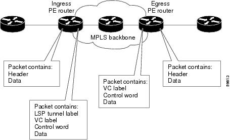
How ATM AAL5 SDUs Move Between PE Routers
ATM AAL5 over MPLS encapsulates ATM AAL5 service data units (SDUs) in MPLS packets and forwards them across the MPLS network. Each AAL5 SDU is transported as a single packet. The following steps outline the process of encapsulating the SDU.
Ingress PE router
1.
2.
–
–
3.
Egress PE router
1.
2.
3.
Figure 1 illustrates this process.
Figure 1 ATM AAL5 Packets as They Traverse the MPLS Backbone
AAL5 Packets Containing OAM Cells
The Cisco 7200, 7400, and 7500 series routers support the transport of F5 end-to-end operational, administrative, and maintenance (OAM) cells. Only Mode 0 is supported. F5 OAM cells are transported over the MPLS backbone with the payload. The OAM cell fits into the payload of a single AAL5 packet.
Notes:
•
•
•
OAM Cell Emulation
If a PE router does not support the transport of OAM cells across an LSP, you can use OAM cell emulation to locally terminate or loopback the OAM cells. You configure OAM cell emulation on both PE routers, which emulates a VC by forming two unidirectional LSPs. You use the oam-ac emulation-enable command on both PE routers to enable OAM cell emulation.
After OAM cell emulation is enabled on a router, you can configure and manage the ATM VC in the same manner as you would a terminated VC. A VC that has been configured with OAM cell emulation can send loopback cells at configured intervals toward the local CE router. The endpoint can be either of the following:
•
•
The OAM cells include the following:
•
•
These cells identify and report defects along a VC. When a physical link or interface failure occurs, intermediate nodes insert OAM AIS cells into all the downstream devices affected by the failure. When a router receives an AIS cell, it marks the ATM VC down and sends an RDI cell to let the remote end know about the failure.
See theConfigure OAM Cell Emulation for ATM AAL5 over MPLS section for information on configuring OAM cell emulation.
ATM Cell Relay over MPLS
ATM Cell Relay over MPLS transports single ATM cells over the MPLS backbone. The AToM circuit is configuring on permanent virtual circuits. In this release, only PVC mode, single cell relay is supported.
How ATM Cells Move Between PE Routers
ATM Cell Relay over MPLS encapsulates ATM cells in MPLS packets and forwards them across the MPLS network. Each MPLS packet contains one ATM cell. In other words, each ATM cell is transported as a single packet. The following steps outline the process of encapsulating the ATM cell.
Ingress PE Router
1.
–
Explicit forward congestion indication (EFCI) bit — Used by ATM switches to indicate congestion experienced by forwarded data cells.
Cell loss priority (CLP) bit — indicates whether a cell should be dropped if it encounters extreme congestion as it moves through the ATM network.
–
2.
Egress PE Router
1.
2.
Figure 2 illustrates this process.
Figure 2 ATM Cell Packets as They Traverse the MPLS Backbone
ATM Packets Containing OAM Cells
If F5 end-to-end operational, administrative, and maintenance (OAM) cells are included in a packet, they are transported over the MPLS backbone with the payload. The OAM cell fits into the payload of a single packet. The Cisco 7200, 7400, and 7500 series routers support the transport of F5 end-to-end OAM cells. Only
Ethernet over MPLS
How Ethernet PDUs Move Between PE Routers
Ethernet over MPLS works by encapsulating Ethernet PDUs in MPLS packets and forwarding them across the MPLS network. Each PDU is transported as a single packet. The following steps outline the process of encapsulating the PDU.
Ingress PE Router:
1.
2.
Egress PE Router
1.
2.
Figure 3 illustrates this process.
Figure 3 Ethernet Packets as They Traverse the MPLS Backbone
Frame Relay over MPLS
How Frame Relay PDUs Move Between PE Routers
Frame Relay over MPLS encapsulates Frame Relay protocol data units (PDUs) in MPLS packets and forwards them across the MPLS network. The process of transporting the PDU differs, depending on whether you set up DLCI-to-DLCI connections or port-to-port connections. The following sections explain both processes.
How Frame Relay Packets Move Between PE Routers with DLCI-to-DLCI Connections
The following steps outline the process of encapsulating the PDU in a Frame Relay configuration with DLCI-to-DLCI connections.
Ingress PE router
1.
2.
–
–
–
–
3.
Egress PE router
1.
2.
3.
Figure 4 illustrates this process.
Figure 4 Frame Relay Packets as They Traverse the MPLS Backbone
How Frame Relay Packets Move Between PE Routers with Port-to-Port Connections
When you set up a port-to-port connection between PE routers, you use HDLC mode to transport the Frame Relay encapsulated packets. In HDLC mode, the whole HDLC packet is transported. Only the HDLC flags and FCS bits are removed. The contents of the packet are not used or changed, including the FECN, BECN, and DE bits. For more information about the HDLC packets, see the "How HDLC Packets Move Between PE Routers" section.
Local Management Interface and Frame Relay over MPLS
Local Management Interface (LMI) is a protocol that communicates status information about permanent virtual circuits (PVCs). When a PVC is added, deleted, or changed, the LMI notifies the endpoint of the status change. LMI also provides a polling mechanism that verifies that a link is up.
How LMI Works
To determine the PVC status, LMI checks that a PVC is available from the reporting device to the Frame Relay end-user device. If PVC is available, LMI reports that the status is "Active." A status of Active means that all interfaces, line protocols and core segments are operational between the reporting device and the Frame Relay end-user device. If any of those components is not available, the LMI reports a status of "Inactive."
Note
Figure 5 is a sample topology that helps illustrate how LMI works.
Figure 5 Sample Topology
In Figure 5, note the following:
•
•
•
•
How the LMI protocol behaves depends on whether you have DLCI-to-DLCI or port-to-port connections.
DLCI-to-DLCI Connections
If you have DLCI-to-DLCI connections, LMI runs locally on the Frame Relay ports between the PE and CE devices.
•
•
–
–
–
–
For data terminal equipment (DTE)/DCE configurations, the following LMI behavior exists:
The Frame Relay device accessing the network (DTE) does the polling. The network device (DCE) responds to the LMI polls. Therefore, if a problem exists on the DTE side, the DCE is not aware of the problem, because it does not poll.
Port-to-Port Connections
If you have port-to-port connections, the PE routers do not participate in the LMI status-checking procedures. LMI operates between the customer edge (CE) routers only. The CE routers must be configured as DCE-DTE or NNI-NNI.
HDLC over MPLS
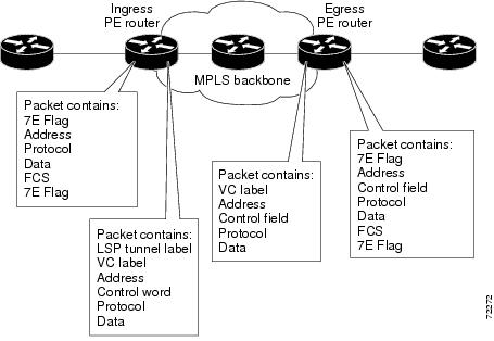
How HDLC Packets Move Between PE Routers
HDLC over MPLS encapsulates HDLC protocol data units (PDUs) in MPLS packets and forwards them across the MPLS network. The PE routers do not participate in any protocol negotiation or authentication. The following steps outline the process of encapsulating the PDU.
Ingress PE Router
1.
2.
Egress PE Router
1.
2.
Figure 6 illustrates this process.
Figure 6 HDLC Packets as They Traverse the MPLS Backbone
PPP over MPLS
How PPP Packets Move Between PE Routers
PPP over MPLS encapsulates PPP PDUs in MPLS packets and forwards them across the MPLS network. The PE routers do not participate in any protocol negotiation or authentication. The following steps outline the process of encapsulating the PDU.
Ingress PE Router
1.
2.
Egress PE Router
1.
2.
Figure 7 illustrates this process.
Figure 7 PPP Packets as They Traverse the MPLS Backbone
AToM and Quality of Service
This section explains the Quality of service (QoS) functionality available for the Cisco 7200, 7400, and 7500 series routers.
For configuration steps and examples, see the "Configuring Quality of Service" section.
Quality of service enables a network to control and predictably manage a variety of networked applications and traffic types. As networks carry more complex, time-critical data, such as audio and video, QoS prioritizes the traffic to ensure that each application gets the service it requires.
MPLS provides QoS using the three experimental bits in a label to determine the queue of packets. You statically set the experimental bits in both the VC label and the LSP tunnel label, because the LSP tunnel label might be removed at the penultimate router. For more information about QoS, see the following documents:
•
•
•
The following sections explain the transport-specific implementations of QoS.
ATM AAL5 over MPLS and QoS
ATM AAL5 over MPLS provides QoS using the three experimental bits in a label to determine the priority of packets. You can either statically set the experimental bits or use the CLP bits to determine the experimental bit settings.
If you do not assign values to the experimental bits, the priority bits in the header's "tag control information" field are set to zero.
Do not use dCEF mode when setting the EXP bits.
ATM Cell Relay over MPLS and QoS
ATM Cell Relay does not support QoS.
Ethernet over MPLS and QoS
Ethernet over MPLS provides QoS by using the three experimental bits in a label to determine the priority of packets. Ethernet over MPLS achieves QoS by using either of the following methods:
•
•
If you do not assign values to the experimental bits, the priority bits in the 802.1Q header's "tag control information" field are written into the experimental bit fields.
On the Cisco 7500 series routers, dCEF must be enabled before you set the experimental bits.
Frame Relay over MPLS and QoS
Frame Relay over MPLS provides QoS using the three experimental bits in a label to determine the priority of PDUs. If you do not assign values to the experimental bits, the priority bits in the header's "tag control information" field are set to zero.
On the Cisco 7500 series routers, dCEF must be enabled before you set the experimental bits.
Frame Relay over MPLS and Policing
Frame relay policing operates on incoming PVC traffic. When enabled on the interface, policing prevents traffic congestion by treating traffic as either committed or excess. Committed traffic is equal to or less than the committed parameter allowed within a given time. Excess traffic exceeds the committed burst parameter allowed within a given time.
The following method determines how a packet is treated:
A PE router receives a Frame Relay packet as follows:
•
•
HDLC over MPLS and PPP over MPLS and QoS
HDLC over MPLS and PPP over MPLS provide QoS using the three experimental bits in a label to determine the priority of PDUs. If you do not assign values to the experimental bits, zeros are written into the experimental bit fields.
On the Cisco 7500 series routers, enable dCEF before setting the experimental bits. Because of a restriction, dCEF has no effect on the manner in which packets are processed. All packets are processed by the router switch processor, whether CEF or DCEF is enabled.
Benefits
The following list explains some of the benefits of enabling Layer 2 packets to be sent in the MPLS network:
•
•
•
What To Do Next
See the following MPLS AToM documentation for more information:
•
•
•