-
Cisco IOS Voice, Video, and Fax Command Reference, Release 12.2
-
Read me
-
About Cisco IOS Software Documentation
-
Using Cisco IOS Software
-
Cisco IOS Voice, Video, and Fax Commands: A through C
-
Cisco IOS Voice, Video, and Fax Commands: D through F
-
Cisco IOS Voice, Video, and Fax Commands: G through P
-
Cisco IOS Voice, Video, and Fax Commands: R through Sh
-
Cisco IOS Voice, Video, and Fax Commands: Si through Z
-
Index
-
 Feedback
Table Of Contents
Cisco IOS Voice, Video, and Fax Commands:
G Through Ph323-gateway voip bind srcaddr
mmoip aaa method fax accounting
mmoip aaa method fax authentication
mmoip aaa receive-accounting enable
mmoip aaa receive-authentication enable
mmoip aaa receive-id secondary
mmoip aaa send-accounting enable
mmoip aaa send-authentication enable
modem passthrough (voice-service)
mta receive maximum-recipients
playout-delay mode (dial-peer)
playout-delay mode (voice-port)
pots distinctive-ring-guard-time
Cisco IOS Voice, Video, and Fax Commands:
G Through P
This chapter presents the commands to configure and maintain Cisco IOS voice, video, and fax applications. The commands are presented in alphabetical order beginning with G. Some commands required for configuring voice, video, and fax may be found in other Cisco IOS command references. Use the command reference master index or search online to find these commands.
For detailed information on how to configure these applications and features, refer to the Cisco IOS Voice, Video, and Fax Configuration Guide.
gatekeeper
To enter gatekeeper configuration mode, use the gatekeeper command in global configuration mode.
gatekeeper
Syntax Description
This command has no arguments or keywords.
Defaults
Disabled
Command Modes
Global configuration
Command History
Usage Guidelines
Press Ctrl-Z or use the exit command to exit gatekeeper configuration mode.
Examples
The following example brings the gatekeeper online:
gatekeeperno shutdowngateway
To enable the H.323 Voice over IP (VoIP) gateway, use the gateway command in global configuration mode. To disable the gateway, use the no form of this command.
gateway
no gateway
Syntax Description
This command has no arguments or keywords.
Defaults
The gateway is unregistered.
Command Modes
Global configuration
Command History
11.3(6)NA2
This command was introduced on the Cisco 3600 series routers and Cisco AS5300 and Cisco AS5800 universal access servers.
Usage Guidelines
Use the gateway command to enable H.323 VoIP gateway functionality. After you enable the gateway, it will attempt to discover a gatekeeper by using the H.323 RAS GRQ message. If you enter no gateway voip, the VoIP gateway will unregister with the gatekeeper via the H.323 RAS URQ message.
Examples
The following example enables the gateway:
gatewaygroup
To create a session-group and associate it with a specified session-set, use the group command in backhaul session manager configuration mode. To delete the group, use the no form of this command.
group group-name set set-name
no group group-name set set-name
Syntax Description
Defaults
No default behavior or values.
Command Modes
Backhaul session manager configuration
Command History
Examples
To associate the group named Group5 with the set named Set1, see the following example:
Router(config-bsm)# group group5 set set1Related Commands
group auto-reset
To configure the maximum auto-reset value, use the group auto-reset command in backhaul session manager configuration mode. To set the value to the default value, use the no form of this command.
group group-name auto-reset count
no group group-name auto-reset count
CautionDo not change this parameter unless instructed to do so by Cisco technical support. There are relationships between group parameters that can cause sessions to fail if not set correctly.
Syntax Description
group-name
Session-group name.
auto-reset count
Maximum number of auto-resets. Range is 0 through 255.
Defaults
5
Command Modes
Backhaul session manager configuration
Command History
Examples
To configure the maximum auto-reset value for the group named Group5 to 6, see the following example:
Router(config-bsm)# group group5 auto-reset 6Related Commands
group cumulative-ack
To configure maximum cumulative acknowledgments, use the group cumulative-ack command in backhaul session manager configuration mode. Maximum cumulative acknowledgments are the maximum number of segments that are received before an acknowledgment is sent. To set the value to the default value, use the no form of this command.
group group-name cumulative ack count
no group group-name cumulative ack count
Caution
Syntax Description
group-name
Session-group name.
cumulative ack count
Maximum number of segments received before acknowledgment. Range is 0 through 255.
Defaults
3
Command Modes
Backhaul session manager configuration
Command History
Examples
To set the cumulative acknowledgment maximum for Group5 to 4, see the following example:
Router(config-bsm)# group group5 cumulative-ack 4Related Commands
group out-of-sequence
To configure maximum out-of-sequence segments that are received before an EACK is sent, use the group out-of-sequence command in backhaul session manager configuration mode. To set the value to the default value, use the no form of this command.
group group-name out-of-sequence count
no group group-name out-of-sequence count
Caution
Syntax Description
group-name
Session-group name.
out-of-sequence count
Maximum number of out-of-sequence segments. Range is 0 through 255.
Defaults
3
Command Modes
Backhaul session manager configuration
Command History
Examples
To set the out-of-sequence maximum for Group5 to 4, see the following example:
Router(config-bsm)# group group5 out-of-sequence 4Related Commands
group receive
To configure maximum receive segments, use the group receive command in backhaul session manager configuration mode. To set the value to the default value, use the no form of this command.
group group-name receive count
no group group-name receive count
Caution
Syntax Description
Defaults
32
Command Modes
Backhaul session manager configuration
Command History
Examples
To set the receive maximum to 10 for Group5, see the following example:
Router(config-bsm)# group group5 receive 10Related Commands
group retransmit
To configure maximum retransmits, use the group retransmit command in backhaul session manager configuration mode. To set the value to the default value, use the no form of this command.
group group-name retransmit count
no group group-name retransmit count
Caution
Syntax Description
group-name
Session-group name.
retransmit count
Maximum number of retransmits. Range is 0 through 255.
Defaults
2
Command Modes
Backhaul session manager configuration
Command History
Examples
To set the retransmit maximum for Group5 to 3, see the following example:
Router(config-bsm)# group group5 retrans 3Related Commands
group timer cumulative-ack
To configure cumulative acknowledgment timeout, use the group timer cumulative ack command in backhaul session manager configuration mode. Cumulative acknowledgment timeout is the maximum number of milliseconds RUDP will delay before sending an acknowledgment for a received segment. To set the value to the default value, use the no form of this command.
group group-name timer cumulative ack time
no group group-name timer cumulative ack time
Caution
Syntax Description
group-name
Session-group name.
timer cumulative ack time
Number of milliseconds RUDP will delay. Range is 100 through 65535.
Defaults
100
Command Modes
Backhaul session manager configuration
Command History
Examples
To set the cumulative acknowledgment timer for Group5 to 325, see the following example:
Router(config-bsm)# group group5 timer cumulative-ack 325Related Commands
group timer keepalive
To configure keepalive (or null segment) timeout, use the group timer keepalive command in backhaul session manager configuration mode. Keepalive timeout is the number of milliseconds RUDP will wait before sending a keepalive segment. To set the value to the default value, use the no form of this command.
group group-name timer keepalive time
no group group-name timer keepalive time
Caution
Syntax Description
group-name
Session-group name.
timer keepalive time
Number of milliseconds before RUDP sends a keepalive segment. Range is 100 through 65535.
Defaults
1000
Command Modes
Backhaul session manager configuration
Command History
Examples
To configure the keepalive timer for Group5 to 2050 milliseconds, see the following example:
Router(config-bsm)# group group5 timer keepalive 2050Related Commands
group timer retransmit
To configure retransmission timeout, use the group timer retransmit command in backhaul session manager configuration mode. Retransmission timeout is the number of milliseconds RUDP will wait to receive an acknowledgment for a segment. To set the value to the default value, use the no form of this command.
group group-name timer retransmit time
no group group-name timer retransmit time
Caution
Syntax Description
group-name
Session-group name.
timer retransmit time
Number of milliseconds RUDP will delay. Range is 100 through 65535.
Defaults
300
Command Modes
Backhaul session manager configuration
Command History
Usage Guidelines
The retransmit timer must be greater than the cumulative-ack timer.
Examples
To set the retransmit timer for Group5 to 650, see the following example:
Router(config-bsm)# group group5 timer retransmit 650Related Commands
group timer transfer
To configure state transfer timeout, use the group timer transfer command in backhaul session manager configuration mode. To set the value to the default value, use the no form of this command.
group group-name timer transfer time
no group group-name timer transfer time
Caution
Syntax Description
group-name
Session-group name.
timer transfer time
Maximum number of milliseconds RUDP will wait for a transfer request. The range is 0 to 65535 milliseconds.
Defaults
2000
Command Modes
Backhaul session manager configuration
Command History
Examples
To set the state transfer timer for Group5 to 1800, see the following example:
Router(config-bsm)# group group5 timer transfer-state 1800Related Commands
gw-accounting
To enable Voice over IP (VoIP) gateway-specific accounting and define the accounting method, use the gw-accounting command in global configuration mode. To disable gateway-specific accounting, use the no form of this command.
gw-accounting {h323 [vsa] | syslog | voip}
no gw-accounting {h323 [vsa] | syslog | voip}
Syntax Description
Defaults
Disabled
Command Modes
Global configuration
Command History
Usage Guidelines
To collect basic start-stop connection accounting data, the gateway must be configured to support gateway-specific H.323 accounting functionality. The gw-accounting command enables you to send accounting data to the RADIUS server in one of four ways:
•
For more information about RADIUS and the use of IETF-defined attributes, see the Cisco IOS Security Configuration Guide.
•
<session id>/<call leg setup time>/<gateway id>/<connection id>/<call origin>/
<call type>/<connect time>/<disconnect time>/<disconnect cause>/<remote ip address>
Table 21 shows the field attributes that you use with the overloaded session-ID method and a brief description of each.
Because of the limited size of the Acct-Session-Id string, it is not possible to embed very many information elements in it. Therefore, this feature supports only a limited set of accounting information elements.
Use the gw-accounting h323 command to configure the overloaded session ID method of applying H.323 gateway-specific accounting.
•
protocol: attribute sep value *"Protocol" is a value of the Cisco "protocol" attribute for a particular type of authorization. "Attribute" and "value" are an appropriate attribute/value (AV) pair defined in the Cisco TACACS+ specification, and "sep" is "=" for mandatory attributes and "*" for optional attributes. This allows the full set of features available for TACACS+ authorization to also be used for RADIUS.
The VSA fields and their ASCII values are listed in Table 22.
Use the gw-accounting h323 vsa command to configure the VSA method of applying H.323 gateway-specific accounting.
•
<server timestamp> <gateway id> <message number> : <message label> : <list of AV
pairs>
The syslog messages fields are listed in Table 23.
Use the gw-accounting syslog command to configure the syslog record method of gathering H.323 accounting data.
Examples
The following example configures basic H.323 accounting using IETF RADIUS attributes:
gw-accounting h323The following example configures H.323 accounting using VSA RADIUS attributes:
gw-accounting h323 vsagw-type-prefix
To configure a technology prefix in the gatekeeper, use the gw-type-prefix command in gatekeeper configuration mode. To remove the technology prefix, use the no form of this command.
gw-type-prefix type-prefix [[hopoff gkid1] [hopoff gkid2] [hopoff gkidn] [seq | blast]] [default-technology] [[gw ipaddr ipaddr [port]]]
no gw-type-prefix type-prefix [[hopoff gkid1] [hopoff gkid2] [hopoff gkidn] [seq | blast]] [default-technology] [[gw ipaddr ipaddr [ port]]]
Syntax Description
Defaults
By default, no technology prefix is defined, and LRQs are sent sequentially to all the gatekeepers listed.
Command Modes
Gatekeeper configuration
Command History
Usage Guidelines
More than one gateway can register with the same technology prefix. In such cases, a random selection is made of one of them.
You do not have to define a technology prefix to a gatekeeper if there are gateways configured to register with that prefix and if there are no special flags (hopoff gkid or default-technology) that you want to associate with that prefix.
You need to configure the gateway type prefix of all remote technology prefixes that will be routed through this gatekeeper.
Examples
The following example defines two gatekeepers for technology zone 3:
gw-type-prefix 3#* hopoff c2600-1-gk hopoff c2514-1-gkRelated Commands
h225 timeout tcp establish
To set the H.225 TCP timeout value for Voice over IP (VoIP) dial peers, use the h225 timeout tcp establish command in voice class configuration mode. To set the timeout value to its default, use the no form of this command.
h225 timeout tcp establish seconds
no h225 timeout tcp establish
Syntax Description
seconds
Specifies the number of seconds for the timeout. Possible values are 0 to 30. The default is 15. If you specify 0, the H.225 TCP timer is disabled.
Defaults
The default timeout value is 15 seconds.
Command Modes
Voice class configuration
Command History
12.1(2)T
This command was introduced on the Cisco 1700, 2500, 2600, 3600, 7200 series routers, AS5300 universal access server, uBR900 series, and uBR924.
Examples
The following example configures a timeout of 10 seconds, which is associated with the H.323 voice class labeled 1:
voice class h323 1h225 timeout tcp establish 10Related Commands
h323 asr
To enable application-specific routing (ASR) and specify the maximum bandwidth for a proxy, use the h323 asr command in interface configuration mode. To remove a bandwidth setting but keep ASR enabled, use no form of this command.
h323 asr [bandwidth max-bandwidth]
no h323 asr [bandwidth max-bandwidth]
Syntax Description
Defaults
ASR is disabled.
Command Modes
Interface configuration
Command History
11.3(2)NA
This command was introduced on the Cisco 2500 and 3600 series routers.
12.0(3)T
This command was integrated into Cisco IOS Release 12.0(3)T.
Usage Guidelines
This command is independent of the h323 interface command.
This command is not supported on Frame Relay or ATM interfaces for the Cisco MC3810 multiservice concentrator.
Note
Examples
The following example enables ASR and specifies a maximum bandwidth of 10,000 kbps:
h323 asr bandwidth 10000h323 call start
To force the H.323 Version 2 gateway to use Fast Connect or Slow Connect procedures for all H.323 calls, use the h323 call start command in voice-service configuration mode. To restore the default condition, use the no form of this command.
h323 call start {fast | slow}
no h323 call start
Syntax Description
fast
Gateway uses H.323 Version 2 (Fast Connect) procedures.
slow
Gateway uses H.323 Version 1 (Slow Connect) procedures.
Defaults
The default is fast.
Command Modes
Voice-service configuration
Command History
Usage Guidelines
In Cisco IOS Release 12.1(3)XI and later releases, H.323 Voice over IP (VoIP) gateways by default use H.323 Version 2 (Fast Connect) for all calls including those initiating RSVP. Previously, gateways used only Slow Connect procedures for RSVP calls. To enable Cisco IOS Release 12.1(3)XI gateways to be backward compatible with earlier releases of Cisco IOS Release 12.1 T, the h323 call start command forces the originating gateway to initiate calls using Slow Connect.
This h323 call start command is configured as part of the global voice-service configuration for VoIP services. It does not take effect unless the call start system voice-class configuration command is configured in the VoIP dial peer.
Examples
The following example selects Slow Connect procedures for the gateway:
voice service voiph323 call start slowRelated Commands
h323 gatekeeper
To specify the gatekeeper associated with a proxy and to control how the gatekeeper is discovered, use the h323 gatekeeper command in interface configuration mode. To disassociate the gatekeeper, use the no form of this command.
h323 gatekeeper [id gatekeeper-id] {ipaddr ipaddr [port] | multicast}
no h323 gatekeeper [id gatekeeper-id] {ipaddr ipaddr [port] | multicast}
Syntax Description
Defaults
No gatekeeper is configured for the proxy.
Command Modes
Interface configuration
Command History
11.3(2)NA
This command was introduced on the Cisco 2500 and 3600 series routers.
Usage Guidelines
You must enter the h323 interface and h323 h323-id commands before using this command. The h323 gatekeeper command must be specified on your Cisco IOS platform or the proxy will not go online. The proxy will use the interface address as its RAS signaling address.
Examples
The following example sets up a unicast discovery to a gatekeeper whose name is unknown:
h323 gatekeeper ipaddr 192.168.5.2The following example sets up a multicast discovery for a gatekeeper of a particular name:
h323 gatekeeper id gk.zone5.com multicastRelated Commands
h323 h323-id
Registers an H.323 proxy alias with a gatekeeper.
h323 interface
Specifies the interface from which the proxy will take its IP address.
h323-gateway voip bind srcaddr
To designate a source IP address for the voice gateway, use the h323-gateway voip bind srcaddr command in interface configuration mode. To remove the source IP address, use the no form of the command.
h323-gateway voip bind srcaddr ip-address
no h323-gateway voip bind srcaddr
Syntax Description
Defaults
No default behaviors or values.
Command Modes
Interface configuration
Command History
12.1(2)T
This command was introduced on the Cisco 1700, 2500, 2600, 3600, and 7200 series routers, the AS5300 universal access server, and the uBR924.
Usage Guidelines
You can issue this command on any interface in the router. You do not have to issue it on the interface that you defined as the voice gateway interface (although it may be more convenient to do so). Issuing the command for one interface assigns the source IP address for the entire router.
Examples
The following example assigns a source IP address of 10.1.1.1:
h323-gateway voip bind srcaddr 10.1.1.1h323-gateway voip h323-id
To configure the H.323 name of the gateway that identifies this gateway to its associated gatekeeper, use the h323-gateway voip h323-id command in interface configuration mode. To disable this defined gateway name, use the no form of this command.
h323-gateway voip h323-id interface-id
no h323-gateway voip h323-id interface-id
Syntax Description
Defaults
No gateway identification is defined.
Command Modes
Interface configuration
Command History
11.3(6)NA2
This command was introduced on the Cisco 2500 and 3600 series routers and the Cisco AS5300 universal access server.
Examples
The following example configures Ethernet interface 0.0 as the gateway interface. In this example, the gateway ID is GW13@cisco.com.
interface Ethernet0/0ip address 172.16.53.13 255.255.255.0h323-gateway voip interfaceh323-gateway voip id GK15.cisco.com ipaddr 172.16.53.15 1719h323-gateway voip h323-id GW13@cisco.comh323-gateway voip tech-prefix 13#Related Commands
h323-gateway voip id
To define the name and location of the gatekeeper for a specific gateway, use the h323-gateway voip id command in interface configuration mode. To disable this gatekeeper identification, use the no form of this command.
h323-gateway voip id gatekeeper-id {ipaddr ip-address [port-number] | multicast}
[priority number]no h323-gateway voip id gatekeeper-id {ipaddr ip-address [port-number] | multicast}
[priority number]Syntax Description
Defaults
No gatekeeper identification is defined.
Command Modes
Interface configuration
Command History
Usage Guidelines
This command tells the H.323 gateway associated with this interface which H.323 gatekeeper to talk to and where to locate it. The gatekeeper ID configured here must exactly match the gatekeeper ID in the gatekeeper configuration.
You can configure up to two alternate gatekeepers.
The IP address of the gatekeeper does not have to be explicit; you can also use the multicast option. Multicasting saves bandwidth by forcing the network to replicate packets only when necessary. The multicast option, shown below, notifies every gatekeeper in the LAN using a universal address, 224.0.1.41.
h323-gateway voip id GK1 multicast
h323-gateway voip id GK2 ipaddr 172.18.193.65 1719
Examples
The following example configures Ethernet interface 0.0 as the gateway interface and defines a specific gatekeeper for it. In this example, the gatekeeper ID is GK15.cisco.com and its IP address is 172.16.53.15 (using port 1719).
interface Ethernet0/0ip address 172.16.53.13 255.255.255.0h323-gateway voip interfaceh323-gateway voip id GK15.cisco.com ipaddr 172.16.53.15 1719h323-gateway voip h323-id GW13@cisco.comh323-gateway voip tech-prefix 13#Related Commands
h323-gateway voip interface
To configure an interface as an H.323 gateway interface, use the h323-gateway voip interface command in interface configuration mode. To disable H.323 gateway functionality for an interface, use the no form of this command.
h323-gateway voip interface
no h323-gateway voip interface
Syntax Description
This command has no arguments or keywords.
Defaults
Disabled
Command Modes
Interface configuration
Command History
11.3(6)NA2
This command was introduced on the Cisco 2500 and 3600 series routers and the AS5300 universal access server.
Examples
The following example configures Ethernet interface 0.0 as the gateway interface. In this example, the h323-gateway voip interface command configures this interface as an H.323 interface.
interface Ethernet0/0ip address 172.16.53.13 255.255.255.0h323-gateway voip interfaceh323-gateway voip id GK15.cisco.com ipaddr 172.16.53.15 1719h323-gateway voip h323-id GW13@cisco.comh323-gateway voip tech-prefix 13#Related Commands
h323-gateway voip tech-prefix
To define the technology prefix that the gateway will register with the gatekeeper, use the h323-gateway voip tech-prefix command in interface configuration mode. To disable this defined technology prefix, use the no form of this command.
h323-gateway voip tech-prefix prefix
no h323-gateway voip tech-prefix prefix
Syntax Description
Defaults
Disabled
Command Modes
Interface configuration
Command History
11.3(6)NA2
This command was introduced on the Cisco 2500 and 3600 series routers and the Cisco AS5300 universal access server.
Usage Guidelines
This command defines a technology prefix that the gateway will then register with the gatekeeper. Technology prefixes can be used as a discriminator so that the gateway can tell the gatekeeper that a certain technology is associated with a particular call (for example, 15# could mean a fax transmission), or it can be used like an area code for more generic routing. No standard currently defines what the numbers in a technology prefix mean. By convention, technology prefixes are designated by a pound symbol (#) as the last character.
Note
Examples
The following example configures Ethernet interface 0.0 as the gateway interface. In this example, the technology prefix is defined as 13#.
interface Ethernet0/0ip address 172.16.53.13 255.255.255.0h323-gateway voip interfaceh323-gateway voip id GK15.cisco.com ipaddr 172.16.53.15 1719h323-gateway voip h323-id GW13@cisco.comh323-gateway voip tech-prefix 13#Related Commands
h323 h323-id
To register an H.323 proxy alias with a gatekeeper, use the h323 h323-id command in interface configuration mode. To remove an H.323 proxy alias, use the no form of this command.
h323 h323-id h323-id
no h323 h323-id h323-id
Syntax Description
h323-id
Specifies the name of the proxy. It is recommended that this name be a fully qualified e-mail ID, with the domain name being the same as that of its gatekeeper.
Defaults
No H.323 proxy alias is registered.
Command Modes
Interface configuration
Command History
11.3(2)NA
This command was introduced on the Cisco 2500 and 3600 series routers.
12.0(3)T
This command was integrated into Cisco IOS Release 12.0(3)T.
Usage Guidelines
Each entry registers a specified H.323 ID proxy alias to a gatekeeper. Typically, these aliases are either simple text strings or legitimate e-mail IDs.
Note
Examples
The following example registers an H.323 proxy alias called proxy1@zone5.com with a gatekeeper:
h323 h323-id proxy1@zone5.comRelated Commands
h323 interface
To select an interface whose IP address will be used by the proxy to register with the gatekeeper, use the h323 interface command in interface configuration mode. To use the default port, use the no h323 interface command and then the h323 interface command.
h323 interface [port-number]
no h323 interface [port-number]
Syntax Description
Defaults
Default port number is image dependent as described in the Syntax Description.
Command Modes
Interface configuration
Command History
Usage Guidelines
At proxy startup, Cisco IOS software checks for the presence of the VoIP gateway subsystem. If the subsystem is found to be present, the proxy code opens and listens for call setup requests on the new port. The proxy then registers this port with the gatekeeper.
Examples
The following example shows how to configure Ethernet interface 0 for incoming call setup requests:
interface ethernet0h323 interfaceRelated Commands
h323 qos
To enable quality of service (QoS) on the proxy, use the h323 qos command in interface configuration mode. To disable QoS, use the no form of this command.
h323 qos {ip-precedence value | rsvp {controlled-load | guaranteed-qos}}
no h323 qos {ip-precedence value | rsvp {controlled-load | guaranteed-qos}}
Syntax Description
Defaults
No QoS is configured.
Command Modes
Interface configuration
Command History
11.3(2)NA
This command was introduced on the Cisco 2500 and 3600 series routers.
Usage Guidelines
You must execute the h323 interface command before using this command.
Both IP precedence and RSVP QoS can be configured by invoking this command twice with the two different QoS forms.
Examples
The following example enables QoS on the proxy:
interface Ethernet0ip address 172.21.127.38 255.255.255.192no ip redirectsip rsvp bandwidth 7000 7000ip route-cache same-interfacefair-queue 64 256 1000h323 interfaceh323 qos rsvp controlled-loadh323 h323-id px1@zone1.comh323 gatekeeper ipaddr 172.21.127.39Related Commands
h323 interface
Specifies the interface from which the proxy will take its IP address.
h323 t120
To enable the T.120 capabilities on your router and to specify bypass or proxy mode, use the h323 t120 command in interface configuration mode.
h323 t120 {bypass | proxy}
Syntax Description
Defaults
Bypass mode
Command Modes
Interface configuration
Command History
12.1(5)T
This command was introduced on on the Cisco 2600, 3600, and 7200 series routers and the Cisco MC3810 multiservice concentrator.
Usage Guidelines
The no form of this command has no function—the only possible commands are h323 t120 bypass and h323 t120 proxy.
Examples
The following example shows how to enable the T.120 capabilities:
proxy h323interface ethernet0h323 t120 proxyRelated Commands
huntstop
To disable all dial-peer hunting if a call fails when using hunt groups, use the huntstop command in dial-peer configuration mode. To reenable dial-peer hunting, use the no form of this command.
huntstop
no huntstop
Syntax Description
This command has no arguments or keywords.
Defaults
Disabled
Command Modes
Dial-peer configuration
Command History
Usage Guidelines
Once you enter this command, no further hunting is allowed if a call fails on the specified dial peer.
Note
Examples
The following example shows how to disable dial-peer hunting on a specific dial peer:
dial peer voice 100 vofrhuntstopThe following example shows how to reenable dial-peer hunting on a specific dial peer:
dial peer voice 100 vofrno huntstopRelated Commands
dial-peer voice
Enters dial-peer configuration mode and specifies the method of voice-related encapsulation.
icpif
To specify the Impairment/Calculated Planning Impairment Factor (ICPIF) for calls sent by a dial peer, use the icpif command in dial-peer configuration mode. To restore the default value, use the no form of this command.
icpif integer
no icpif integer
Syntax Description
integer
Integer, expressed in equipment impairment factor units, that specifies the ICPIF value. Valid entries are 0 to 55. The default is 20.
Defaults
20
Command Modes
Dial-peer configuration
Command History
Usage Guidelines
This command is applicable only to Voice over IP (VoIP) dial peers.
Use the icpif command to specify the maximum acceptable impairment factor for the voice calls sent by the selected dial peer.
Examples
The following example disables the icpif command:
dial-peer voice 10 voipicpif 0idle-voltage
To specify the idle voltage on an Foreign Exchange Station (FXS) voice port, use the idle-voltage command in voice-port configuration mode. To restore the default idle voltage, use the no form of this command.
idle-voltage {high | low}
no idle-voltage
Syntax Description
high
The talk-battery (tip-to-ring) voltage is high (-48V) when the FXS port is idle.
low
The talk-battery (tip-to-ring) voltage is low (-24V) when the FXS port is idle.
Defaults
The idle voltage is -24V.
Command Modes
Voice-port configuration
Command History
12.0(4)T
This command was introduced on the Cisco MC3810 multiservice concentrator.
Usage Guidelines
Some fax equipment and answering machines require a -48V idle voltage to be able to detect an off-hook condition in a parallel phone.
If the idle voltage setting is high, the talk battery reverts to -24V whenever the voice port is active (off hook).
The idle-voltage command applies only to FXS voice ports on Cisco MC3810 multiservice concentrators.
Examples
The following example sets the idle voltage to -48V on voice port 1/1 on a Cisco MC3810 multiservice concentrator:
voice-port 1/1idle-voltage highThe following example restores the default idle voltage (-24V) on voice port 1/1 on a Cisco MC3810 multiservice concentrator:
voice-port 1/1no idle-voltageRelated Commands
ignore
To configure the North American E&M or E&M MELCAS voice port to ignore specific receive bits, use the ignore command in voice-port configuration mode. To restore the default value, use the no form of this command.
ignore {rx-a-bit | rx-b-bit | rx-c-bit | rx-d-bit}
no ignore {rx-a-bit | rx-b-bit | rx-c-bit | rx-d-bit}
Syntax Description
rx-a-bit
Ignores the receive A bit.
rx-b-bit
Ignores the receive B bit.
rx-c-bit
Ignores the receive C bit.
rx-d-bit
Ignores the receive D bit.
Defaults
The default is mode-dependent:
•
–
–
•
–
–
Command Modes
Voice-port configuration
Command History
Usage Guidelines
The ignore command applies to E&M digital voice ports associated with T1/E1 controllers. Repeat the command for each receive bit to be configured. Use this command with the define command.
Examples
To configure voice port 1/1 on a Cisco MC3810 multiservice concentrator to ignore receive bits A, B, and C and to monitor receive bit D, enter the following commands:
voice-port 1/1ignore rx-a-bitignore rx-b-bitignore rx-c-bitno ignore rx-d-bitTo configure voice port 1/0/0 on a Cisco 3600 series router to ignore receive bits A, C, and D and to monitor receive bit B, enter the following commands:
voice-port 1/0/0ignore rx-a-bitignore rx-c-bitignore rx-d-bitno ignore rx-b-bitRelated Commands
image encoding
To select a specific encoding method for fax images associated with an MMoIP dial peer, use the image encoding command in dial-peer configuration mode. To restore the default value, use the no form of this command.
image encoding {mh | mr | mmr | passthrough}
no image encoding {mh | mr | mmr | passthrough}
Syntax Description
Defaults
passthrough
Command Modes
Dial-peer configuration
Command History
12.0(4)XJ
This command was introduced.
12.1(1)T
This command was integrated into Cisco IOS Release 12.1(1)T.
Usage Guidelines
Use the image encoding command to specify an encoding method for e-mail fax TIFF images for a specific MMoIP dial peer. This command applies primarily to the on-ramp MMoIP dial peer. Although you can optionally create an off-ramp dial peer and configure a particular image encoding value for that off-ramp call leg, store and forward fax ignores the off-ramp MMoIP setting and sends the file using Modified Huffman encoding.
There are four available encoding methods:
•
•
•
•
The IETF standard for sending fax TIFF images is Modified Huffman encoding with fine or standard resolution. RFC 2301 requires that compliant receivers support TIFF images with MH encoding and fine or standard resolution. If a receiver supports features beyond this minimal requirement, you might want to configure the Cisco AS5300 universal access server to send enhanced-quality documents to that receiver.
The primary reason to use a different encoding scheme from MH is to save network bandwidth. MH ensures interoperability with all Internet fax devices, but it is the least efficient of the encoding schemes for sending fax TIFF images. For most images, MR is more efficient than MH, and MMR is more efficient than MR. If you know that the recipient is capable of receiving more efficient encodings than just MH, store and forward fax allows you to send the most efficient encoding that the recipient can process. For end-to-end closed networks, you can choose any encoding scheme because the off-ramp gateway can process MH, MR, and MMR.
Another factor to consider is the viewing software. Many viewing applications (for example, those that come with Windows 95 or Windows NT) are able to display MH, MR, and MMR. Therefore you should decide, based on the viewing application and the available bandwidth, which encoding scheme is right for your network.
This command applies to both on-ramp and off-ramp store and forward fax functions.
Examples
The following example selects Modified Modified Read as the encoding method for fax TIFF images sent by MMoIP dial peer 10:
dial-peer voice 10 mmoipimage encoding mmrRelated Commands
image resolution
Specifies a particular fax image resolution for a specific MMoIP dial peer.
image resolution
To specify a particular fax image resolution for a specific MMoIP dial peer, use the image resolution command in dial-peer configuration mode. To restore the default value, use the no form of this command.
image resolution {fine | standard | superfine | passthrough}
no image resolution {fine | standard | superfine | passthrough}
Syntax Description
Defaults
passthrough
Command Modes
Dial-peer configuration
Command History
12.0(4)XJ
This command was introduced.
12.1(1)T
This command was integrated into Cisco IOS Release 12.1(1)T.
Usage Guidelines
Use the image resolution command to specify a specific resolution (in pixels per inch) for e-mail fax TIFF images sent by the specified MMoIP dial peer. This command applies primarily to the on-ramp MMoIP dial peer. Although you can optionally create an off-ramp dial peer and configure a particular image resolution value for that off-ramp call leg, store and forward fax ignores the off-ramp MMoIP setting and sends the file using fine resolution.
This command enables you to increase or decrease the resolution of a fax TIFF image, thereby changing not only the resolution but also the size of the fax TIFF file. The IETF standard for sending fax TIFF images is Modified Huffman encoding with fine or standard resolution. The primary reason to configure a different resolution is to save network bandwidth.
This command applies to both on-ramp and off-ramp store and forward fax functions.
Examples
The following example selects the fine resolution (meaning 204-by-196 pixels per inch) for e-mail fax TIFF images associated with MMoIP dial peer 10:
dial-peer voice 10 mmoipimage encoding mhimage resolution fineRelated Commands
image encoding
Selects a specific encoding method for fax images associated with an MMoIP dial peer.
impedance
To specify the terminating impedance of a voice-port interface, use the impedance command in voice-port configuration mode. To restore the default value, use the no form of this command.
impedance {600c | 600r | 900c | complex1 | complex2}
no impedance {600c | 600r | 900c | complex1 | complex2}
Syntax Description
600c
Specifies 600 ohms (complex).
600r
Specifies 600 ohms (real).
900c
Specifies 900 ohms (complex).
complex1
Specifies complex 1.
complex2
Specifies complex 2.
Defaults
600r
Command Modes
Voice-port configuration
Command History
Usage Guidelines
Use the impedance command to specify the terminating impedance of an Foreign Exchange Office (FXO) voice-port interface. The impedance value selected needs to match the specifications from the specific telephony system to which it is connected. Different countries often have different standards for impedance. CO switches in the United States are predominantly 600r. PBXs in the United States are normally either 600r or 900c.
If the impedance is set incorrectly (if there is an impedance mismatch), there will be a significant amount of echo generated (which could be masked if the echo-cancel command has been enabled). In addition, gains might not work correctly if there is an impedance mismatch.
Configuring the impedance on a voice port will change the impedance on both voice ports of a VPM card. This voice port must be shut down and then opened for the new value to take effect.
Examples
The following example configures an FXO voice port on the Cisco 3600 series router for a terminating impedance of 600 ohms (real):
voice-port 1/0/0impedance 600rThe following example configures an E&M voice port on the Cisco MC3810 multiservice concentrator for a terminating impedance of 900 ohms (complex):
voice-port 1/1impedance 900cincoming called-number
To specify a digit string that can be matched by an incoming call to associate the call with a dial peer, use the incoming called-number command in dial-peer configuration mode. To reset the default value, use the no form of this command.
incoming called-number string
no incoming called-number string
Syntax Description
string
Specifies the incoming called telephone number. Valid entries are any series of digits that specify the E.164 telephone number.
Defaults
No incoming called number is defined.
Command Modes
Dial-peer configuration
Command History
Usage Guidelines
When a Cisco device (such as a Cisco AS5300 universal access server or Cisco AS5800 universal gateway) is handling both modem and voice calls, it needs to be able to identify the service type of the call—meaning whether the incoming call to the server is a modem or a voice call. When the access server handles only modem calls, the service type identification is handled through modem pools. Modem pools associate calls with modem resources based on the called number (DNIS). In a mixed environment, in which the server receives both modem and voice calls, you need to identify the service type of a call by using the incoming called-number command.
If you do not use the incoming called-number command, the server attempts to resolve whether an incoming call is a modem or voice call based on the interface over which the call comes. If the call comes in over an interface associated with a modem pool, the call is assumed to be a modem call; if a call comes in over a voice port associated with a dial peer, the call is assumed to be a voice call.
By default, there is no called number associated with the dial peer, which means that incoming calls will be associated with dial peers based on matching calling number with answer address, call number with destination pattern, or calling interface with configured interface.
Use the incoming called-number command to define the destination telephone number for a particular dial peer. For the on-ramp POTS dial peer, this telephone number is the DNIS number of the incoming fax call. For the off-ramp MMoIP dial peer, this telephone number is the destination fax machine telephone number.
This command applies to both Voice over IP (VoIP) and POTS dial peers and applies to both on-ramp and off-ramp store and forward fax functions.
This command is also used to provide a matching VoIP dial peer on the basis of called number when fax or modem pass-through with named service events (NSEs) is defined globally on a terminating gateway.
You can ensure that all calls will match at least one dial peer by using the following commands:
Router(config)# dial-peer voice tag voipRouter(config-dial-peer)# incoming called-number .Examples
The following example configures calls coming in to the server with a called number of 3799262 as being voice calls:
dial peer voice 10 potsincoming called-number 3799262The following example configures the number (310) 555-9261 as the incoming called number for MMoIP dial peer 10:
dial-peer voice 10 mmoipincoming called-number 3105559261info-digits
To automatically prepend two information digits to the beginning of a dialed number associated with the given POTS dial peer, use the info-digits command in dial-peer configuration mode. To keep the router from automatically prepending the two-digit information numbers to the beginning of the POTS dial peer, use the no form of this command.
info-digits string
no info-digits
Syntax Description
Defaults
No default behavior or values.
Command Modes
Dial-peer configuration
Command History
12.2(1)T
This command was introduced on Cisco 2600 series, Cisco 3600 series, and Cisco 3700 series routers and on Cisco AS5300 series universal access servers.
Usage Guidelines
This command is designed to prepend a pair of information digits to the beginning of the dialed number string for the POTS dial peer that will enable you to dynamically redirect the outgoing call. The info-digits command is only available for POTS dial peers.
Examples
The following example prepends the information number string 91 to the beginning of the dialed number for POTS dial peer 10:
dial-peer voice 10 potsinfo-digits 91information-type
To select a particular information type for either an Mail Message over IP (MMoIP) or Plain Old Telephone Service (POTS) dial peer, use the information-type command in dial-peer configuration mode. To reset the default value for this command, use the no form of this command.
information-type {fax | voice}
no information-type {fax | voice}
Syntax Description
fax
Indicates that the information type has been set to store and forward fax.
voice
Indicates that the information type has been set to voice.
Defaults
Voice
Command Modes
Dial-peer configuration
Command History
Usage Guidelines
This command applies to both on-ramp and off-ramp store and forward fax functions.
Examples
The following example sets the information type for MMoIP dial peer 10 to fax:
dial-peer voice 10 mmoipinformation-type faxinput gain
To configure a specific input gain value, use the input gain command in voice-port configuration mode. To disable the selected amount of inserted gain, use the no form of this command.
input gain decibels
no input gain decibels
Syntax Description
decibels
Specifies, in decibels, the amount of gain to be inserted at the receiver side of the interface. Acceptable values are integers from -6 to 14.
Defaults
Zero (0) decibels
Command Modes
Voice-port configuration
Command History
11.3(1)T
This command was introduced.
11.3(1)MA
This command was first supported on the Cisco MC3810 multiservice concentrator.
Usage Guidelines
A system-wide loss plan must be implemented using both the input gain and output attenuation commands. Other equipment (including PBXs) in the system must be considered when creating a loss plan. The default value for this command assumes that a standard transmission loss plan is in effect, meaning that there must be an attenuation of -6 dB between phones. Connections are implemented to provide -6 dB of attenuation when the input gain and output attenuation commands are configured with the default value of 0 dB.
You cannot increase the gain of a signal to the Public Switched Telephone Network (PSTN), but you can decrease it. If the voice level is too high, you can decrease the volume by either decreasing the input gain or increasing the output attenuation.
You can increase the gain of a signal coming into the router. If the voice level is too low, you can increase the input gain by using the input gain command.
Examples
The following example configures a 3-dB gain to be inserted at the receiver side of the interface in the Cisco 3600 series router:
port 1/0/0input gain 3The following example configures a 3-dB gain to be inserted at the receiver side of the interface in the Cisco MC3810 multiservice concentrator:
port 1/1input gain 3Related Commands
output attenuation
Configures a specific output attenuation value for a voice port.
interface (RLM server)
To define the IP addresses of the Redundant Link Manager (RLM) server, use the interface command in interface configuration mode. To disable this function, use the no form of this command.
interface name-tag
no interface name-tag
Syntax Description
name-tag
Name to identify the server configuration so that multiple entries of server configuration can be entered.
Defaults
Disabled
Command Modes
Interface configuration
Command History
Usage Guidelines
Each server can have multiple entries of IP addresses or aliases.
Examples
The following example shows how to configure the access server interfaces for RLM servers named Loopback1 and Loopback2:
interface Loopback1ip address 10.1.1.1 255.255.255.255interface Loopback2ip address 10.1.1.2 255.255.255.255rlm group 1server r1-serverlink address 10.1.4.1 source Loopback1 weight 4link address 10.1.4.2 source Loopback2 weight 3Related Commands
ip precedence (dial-peer)
To set IP precedence (priority) for packets sent by the dial peer, use the ip precedence command in dial-peer configuration mode. To restore the default value, use the no form of this command.
ip precedence number
no ip precedence number
Syntax Description
number
Integer specifying the IP precedence value. Valid entries are from 0 to 7. A value of 0 means that no precedence (priority) has been set.
Defaults
The default value for this command is zero (0).
Command Modes
Dial-peer configuration
Command History
11.3(1)NA
This command was introduced on the Cisco 2500, 3600 series routers and the Cisco AS5300 universal access server.
Usage Guidelines
Use the ip precedence (dial-peer) command to configure the value set in the IP precedence field when voice data packets are sent over the IP network. This command should be used if the IP link utilization is high and the quality of service for voice packets needs to have a higher priority than other IP packets. The ip precedence (dial-peer) command should also be used if RSVP is not enabled and the user would like to give voice packets a higher priority than other IP data traffic.
This command applies to Voice over IP (VoIP) peers.
Examples
The following example sets the IP precedence to 5:
dial-peer voice 10 voipip precedence 5ip udp checksum
To calculate the UDP checksum for voice packets sent by the dial peer, use the ip udp checksum command in dial-peer configuration mode. To disable this feature, use the no form of this command.
ip udp checksum
no ip udp checksum
Syntax Description
This command has no arguments or keywords.
Defaults
Disabled
Command Modes
Dial-peer configuration
Command History
Usage Guidelines
Use the ip udp checksum command to enable UDP checksum calculation for each of the outbound voice packets. This command is disabled by default to speed up the transmission of the voice packets. If you suspect that the connection has a high error rate, you should enable the ip udp checksum command to prevent corrupted voice packets forwarded to the digital signal processor (DSP).
This command applies to Voice over IP (VoIP) peers.
Examples
The following example calculates the UDP checksum for voice packets sent by dial peer 10:
dial-peer voice 10 voipip udp checksumRelated Commands
loop-detect
Enables loop detection for T1 for Voice over ATM, Voice over Frame Relay, and Voice over HDLC.
isdn bind-l3
To configure the ISDN serial interface for backhaul, use the isdn bind-l3 command in interface configuration mode. To disable backhaul on the interface, use the no form of this command.
isdn bind-l3 set-name
no isdn bind-l3 set-name
Syntax Description
Defaults
No default behavior or values.
Command Modes
Interface configuration
Command History
Examples
To configure the ISDN serial interface for backhaul for the set named Set1, see the following example:
Router(config-if)# isdn bind-l3 set1isdn contiguous-bchan
To configure contiguous bearer channel handling on an E1 PRI interface, use the isdn contiguous-bchan command in interface configuration mode. To disable the contiguous B-channel handling, use the no form of this command.
isdn contiguous-bchan
no isdn contiguous-bchan
Syntax Description
This command has no arguments or keywords.
Defaults
By default, contiguous B channel handling is disabled.
Command Modes
Interface configuration
Command History
Usage Guidelines
Use the isdn contiguous-bchan command to specify contiguous bearer channel handling so that B channels 1 through 30, skipping 16, map to time slots 1 through 31. This is available for E1 PRI interfaces only, when the primary-qsig switch type option is configured by using the isdn switch-type command.
Examples
The following example shows the command configuration on the E1 interface of a Cisco 3660 series router E1 interface:
interface Serial5/0:15no ip addressip mroute-cacheno logging event link-statusisdn switch-type primary-qsigisdn overlap-receivingisdn incoming-voice voiceisdn continguous-bchanRelated Commands
isdn switch-type primary-qsig
Configures the primary-qsig switch type for PRI support.
isdn global-disconnect
To allow passage of "release" and "release complete" messages over the voice network, use the isdn global-disconnect command in interface configuration mode. To disable the passage of these messages, use the no form of this command.
isdn global-disconnect
no isdn global-disconnect
Syntax Description
This command has no arguments or keywords.
Defaults
Passage of messages is disabled by default; "release" and "release complete" messages terminate locally by default.
Command Modes
Interface configuration
Command History
12.1(2)T
This command was introduced on the Cisco 2600, 3600, and 7200 series routers and on the Cisco MC3810 multiservice concentrator.
Usage Guidelines
Enter this command under the isdn interface with switch type bri-qsig or pri-qsig. Use the isdn global-disconnect command to allow passage of "release" and "release complete" messages end-to-end across the network. This is required for certain types of QSIG PBXs whose software or features require either Facility or User Info IEs in those messages to be passed end-to-end between the PBXs. All QSIG interfaces that connect the PBXs to the routers must have this command enabled. This command is available when using the BRI QSIG or PRI QSIG switch type in either master or slave mode.
Examples
The following example shows command configuration on the T1 PRI interface of a Cisco 3660 series router:
interface Serial5/0:23no ip addressip mroute-cacheno logging event link-statusisdn switch-type primary-qsigisdn global-disconnectisdn overlap-receivingisdn incoming-voice voiceRelated Commands
isdn protocol-emulate
Configures the interface to serve as either the QSIG slave or the QSIG master.
isdn switch-type
Configures the switch type for BRI or PRI support.
isdn i-number
To configure several terminal devices to use one subscriber line, use the isdn i-number command in interface configuration mode.
isdn i-number n ldn
Syntax Description
n
Subscriber line 1, 2, or 3, as specified in the NTT specification.
ldn
LDN assigned to the router plain old telephone service (POTS) port.
Defaults
Each terminal device uses one subscriber line.
Command Modes
Interface configuration
Command History
Usage Guidelines
Enter the interface bri command before entering the isdn i-number command.
Examples
The following example shows screen output for two LDNs configured under BRI interface 0:
interface bri0isdn i-number 1 5551234isdn i-number 2 5556789exitdial-peer voice 1 potsdestination-pattern 5551234exitdial-peer voice 2 potsdestination-pattern 5556789exitRelated Commands
interface bri
Specifies a BRI interface and enters interface configuration mode.
isdn network-failure-cause
To specify the cause code to pass to the PBX when a call cannot be placed or completed because of internal network failures, use the isdn network-failure-cause command in interface configuration mode. To unconfigure the use of this cause code, use the no form of this command.
isdn network-failure-cause value
no isdn network-failure-cause value
Syntax Description
value
Number from 1 to 127. See Table 24 for a list of failure cause code values.
Defaults
No default behavior or values.
Command Modes
Interface configuration
Command History
12.1(2)T
This command was introduced to the Cisco IOS 12.1(2)T on the Cisco 2600, 3600, and 7200 series routers and on the Cisco MC3810 multiservice concentrator.
Usage Guidelines
The PBX can reroute calls based on the cause code returned by the router.
This command allows the original cause code to be changed to the value specified if the original cause code is not one of the following:
•
•
•
•
•
•
•
•
Table 24 describes the cause codes.
Examples
The following is an example of specifying a cause code to pass to a PBX when a call cannot be placed or completed of internal network failures:
isdn network-failure-cause 28ivr autoload
To load files from a particular TFTP server (as indicated by a defined URL), use the ivr autoload command in global configuration mode. To disable this function, use the no form of this command.
ivr autoload url location
no ivr autoload url location
Syntax Description
url
Indicates that a URL is used to locate the index file that contains a list of all available audio files.
location
Specifies the URL of the index file.
Defaults
No URL is defined.
Command Modes
Global configuration
Command History
12.0(7)T
This command was introduced on the Cisco 2600 and 3600 series routers and the Cisco AS5300 universal access server.
Usage Guidelines
The index file contains a list of audio files (URL) that can be downloaded from the TFTP server. Use the ivr autoload command to download audio files from TFTP to memory. The command only starts up a background process. The background process (loader) does the actual down loading of the files.
The background process first reads the index file from either Flash or TFTP. It parses the files line by line looking for the URL. It ignores lines that start with # as comment lines. Once it has a correct URL, it tries to read that .au file into memory and creates a media object. If there are any errors during the reading of the file, it retries the configured number of times. If the mode is set to "verbose," the loader logs the transaction to console. Once parsing has reached the end of the index file, the background process exits memory.
Perform the following checks before initiating the background process. If one of the checks fail, it indicates the background process is not started, and instead you will see an error response to the command.
•
command is not allowed when prompts are active
•
previous autoload command is still in progress
•
previous command is being replaced
•
The audio files (prompts) loaded using the ivr autoload command are not dynamically swapped out of memory. They are considered as autoloaded prompts as opposed to "dynamic" prompts. (See the ivr prompt memory command for details on dynamic prompts.)
Examples
The following example loads audio files from the TFTP server (located at //jurai/mgindi/tclware/index4):
ivr autoload url tftp://jurai/mgindi/tclware/index4The index file for this example index4 is shown as follows:
more index4tftp://jurai/mgindi/tclware/au/en/en_one.autftp://jurai/mgindi/tclware/au/ch/ch_one.autftp://jurai/mgindi/tclware/au/ch/ch_one.auAn example of an index file on Flash is shown as follows:
flash:indexRelated Commands
ivr prompt memory
Configures the maximum amount of memory that the dynamic audio files (prompts) occupy in memory.
ivr autoload retry
To specify the number of times that the system will try to load audio files from TFTP to memory when there is an error, use the ivr autoload retry command in global configuration mode. To disable this function, use the no form of this command.
ivr autoload retry number
no ivr autoload retry number
Syntax Description
Defaults
Three times
Command Modes
Global configuration
Command History
12.0(7)T
This command was introduced on the Cisco 2600 and 3600 series routers and on the Cisco AS5300 universal access server.
Examples
The following example configures the system to try three times to load audio files:
ivr autoload retry 3Related Commands
ivr prompt memory
Configures the maximum amount of memory that the dynamic audio files (prompts) occupy in memory.
ivr autoload mode
To load files from TFTP to memory using either verbose or silent mode, use the ivr autoload mode command in global configuration mode. To disable this function, use the no form of this command.
ivr autoload mode {verbose url location [retry number]} | {silent url location [retry number]}
no ivr autoload mode {verbose url location [retry number]} | {silent url location
[retry number]}Syntax Description
Defaults
Silent mode
Command Modes
Global configuration
Command History
12.0(7)T
This command was introduced on the Cisco 2600 and 3600 series routers and on the Cisco AS5300 universal access server.
Usage Guidelines
The index file contains a list of audio files (URL) that can be downloaded from the TFTP server. Use the ivr autoload command to download audio files from TFTP to memory. The command only starts up a background process. The background process (loader) does the actual downloading of the files.
The background process first reads the index file from either Flash or TFTP. It parses the files line by line looking for the URL. It ignores lines that start with # as comment lines. Once it has a correct URL, it tries to read that.au file into memory and creates a media object. If there are any errors during the reading of the file, it retries the configured number of times. If the mode is set to verbose, the loader logs the transaction to console. Once parsing has reached the end of the index file, the background process exits memory.
Perform the following checks before initiating the background process. If one of the checks fails, it indicates the background process is not started, and instead you will see an error response to the command.
•
command is not allowed when prompts are active
•
previous autoload command is still in progress
•
previous command is being replaced
•
The audio files (prompts) loaded using the ivr autoload command are not dynamically swapped out of memory. They are considered as autoloaded prompts as opposed to "dynamic" prompts. (See the ivr prompt memory command for details on dynamic prompts.)
Examples
The following example configures verbose mode:
ivr autoload mode verbose url tftp://jurai/mgindi/tclware/index4 retry 3The index file for the example index4 is shown as follows:
more index4tftp://jurai/mgindi/tclware/au/en/en_one.autftp://jurai/mgindi/tclware/au/ch/ch_one.autftp://jurai/mgindi/tclware/au/ch/ch_one.auThe following is an example of index file on Flash:
flash:index
Related Commands
ivr prompt memory
Configures the maximum amount of memory that the dynamic audio files (prompts) occupy in memory.
ivr prompt memory
To configure the maximum amount of memory that the dynamic audio files (prompts) occupy in memory, use the ivr prompt memory command in global configuration mode. To disable the maximum memory size, use the no form of this command.
ivr prompt memory size files number
no ivr prompt memory size files number
Syntax Description
Command Modes
Global configuration
Command History
12.0(7)T
This command was introduced on the Cisco 2600 and 3600 series routers and on the Cisco AS5300 universal access server.
Usage Guidelines
When both the number and size parameters are specified, the minimum memory out of the two will be used for memory calculations.
All the prompts that are not autoloaded or fixed are considered dynamic. Dynamic prompts are loaded in to memory from TFTP or Flash, as and when they are needed. When they are actively used for playing prompts, they are considered to be in "active" state. However, once the prompt playing is complete, these prompts are no longer active and are considered to be in "free" state.
The free prompts either stay in memory or are removed from memory depending on the availability of space in memory for these free prompts. The prompt-mem command essentially specifies a maximum memory to be used for these free prompts.
The free prompts are saved in memory and are queued in a waitQ. When the waitQ is full (either because the totally memory occupied by the free prompts exceeds the maximum configured value or the number of files in the waitQ exceeds maximum configured), oldest free prompts are removed from memory.
Examples
The following example shows how to use the ivr prompt memory command:
ivr prompt memory 2048 files 500Related Commands
ivr autoload
Loads files from a particular TFTP server.
show call prompt-mem-usage
Displays the memory site use by prompts.
line-power
To configure the BRI port to supply line power to the terminal equipment (TE), use the line-power command in interface configuration mode. To disable the line power supply, use the no form of this command.
line-power
no line-power
Syntax Description
This command has no arguments or keywords.
Defaults
The BRI port does not supply line power.
Command Modes
Interface configuration
Command History
Usage Guidelines
This command is supported only if an installed BRI voice module (BVM) or BRI VIC is equipped to supply line power (phantom power).
This command is used only on a BRI port that is operating in NT mode. A BRI port that is operating in TE mode is automatically disabled as a source of line power, and the line-power command is rejected.
When you use the line-power command, the line power provision is activated on a BRI port if the port is equipped with the hardware to supply line power. When you enter the no line-power command, the line power provision is deactivated on a BRI port.
Examples
The following example configures a BRI port to supply power to an attached TE device:
interface bri 1line-powerline-termination
To set the line termination on an E1 controller, use the line-termination command in controller configuration mode. To restore the default value, use the no form of this command.
line-termination { 75-ohm | 120-ohm }
no line-termination
Syntax Description
75-ohm
Matches the balanced BNC 75-ohm interface.
120-ohm
Matches the unbalanced twisted-pair 120-ohm interface.
Defaults
The default value is 120-ohm.
Command Modes
Controller configuration
Command History
12.0(7)XR
This command was introduced.
12.1(1)T
This command was integrated into Cisco IOS Release 12.1(1)T.
Usage Guidelines
This command applies to E1 controllers only.
Examples
The following example shows how to set controller E1 0/0 to a line-termination of 75-ohm:
controller e1 0/0line-termination 75-ohmlink (RLM)
To enable a Redundant Link Manager (RLM) link, use the link command in RLM configuration mode. To disable this function, use the no form of this command.
link {hostname name | address ip-address} source loopback-source weight factor
no link {hostname name | address ip-address} source loopback-source weight factor
Syntax Description
Defaults
Disabled
Command Modes
RLM configuration
Command History
Usage Guidelines
This command is a preference-weighted multiple entries command. Within the same server, the link preference is specified in weighting.
Examples
The following example specifies the RLM group (network access server), the device name, and the link addresses and their weighting preferences:
rlm group 1server r1-serverlink address 10.1.4.1 source Loopback1 weight 4link address 10.1.4.2 source Loopback2 weight 3Related Commands
protocol rlm port
To configure the RLM port number, use the protocol rlm port RLM configuration command. To disable this function, use the no form of this command.
protocol rlm port port-number
no protocol rlm port port-number
Syntax Description
Defaults
3000
Command Modes
RLM configuration
Command History
Usage Guidelines
The port number for the basic RLM connection can be reconfigured for the entire RLM group. Table 87 lists the default RLM port numbers.
Related Commands
loopback
To set the loopback method for testing a T1 or E1 interface, use the loopback command in controller configuration mode. To restore the default value, use the no form of this command.
loopback {diagnostic | local {payload | line} | remote {v54 channel-group channel-number | iboc | esf {payload | line}}}
no loopback
Syntax Description
Defaults
No loopback is configured.
Command Modes
Controller configuration
Command History
Usage Guidelines
You can use a loopback test on lines to detect and distinguish equipment malfunctions caused either by the line and channel service unit/digital service unit (CSU/DSU) or by the interface. If correct data transmission is not possible when an interface is in loopback mode, the interface is the source of the problem.
Examples
The following example shows how to set the diagnostic loopback method on controller T1 0/0:
controller t1 0/0loopback diagnosticThe following example shows how to set the payload loopback method on controller E1 0/0:
controller e1 0/0loopback local payloadloop-detect
To enable loop detection for T1, use the loop-detect command in controller configuration mode. To cancel the loop detect operation, use the no form of this command.
loop-detect
no loop-detect
Syntax Description
This command has no arguments or keywords.
Defaults
Loop detection is disabled.
Command Modes
Controller configuration
Command History
11.3(1)MA
This command was introduced on the Cisco MC3810 multiservice concentrator.
Usage Guidelines
This command applies to Voice over Frame Relay and Voice over ATM on the Cisco MC3810 multiservice concentrator.
Examples
The following example configures loop detection for controller T1 0:
controller t1 0loop-detectRelated Commands
loopback (interface)
Diagnoses equipment malfunctions between an interface and a device.
loss-plan
To specify the analog-to-digital gain offset for an analog Foreign Exchange Office (FXO) or Foreign Exchange Station (FXS) voice port, use the loss-plan command in voice-port configuration mode. To restore the default value, use the no form of this command.
loss-plan {plan1 | plan2 | plan3 | plan4 | plan5 | plan6 | plan7 | plan8 | plan9}
no loss-plan
Syntax Description
Defaults
FXO: A-D gain = 0 dB, D-A gain = 0 dB (loss plan 1)
FXS: A-D gain = -3 dB, D-A gain = -3 dB (loss plan 1)
Command Modes
Voice-port configuration
Command History
Usage Guidelines
The loss-plan command sets the analog signal level difference (offset) between the analog voice port and the digital signal processor (DSP). Each loss plan specifies a level offset in both directions—from the analog voice port to the DSP (A-D) and from the DSP to the analog voice port (D-A).
Use this command to obtain the required levels of analog voice signals to and from the DSP.
The loss-plan command is supported only on Cisco MC3810 multiservice concentrators, on FXO and FXS analog voice ports.
Examples
The following example configures FXO voice port 1/6 for a -3 dB offset from the voice port to the DSP and for a 0 dB offset from the DSP to the voice port:
voice-port 1/6loss-plan plan3The following example configures FXS voice port 1/1 for a 0 dB offset from the voice port to the DSP and for a -7 dB offset from the DSP to the voice port:
voice-port 1/1loss-plan plan6Related Commands
lrq forward-queries
To enable a gatekeeper to forward Location Requests (LRQs) that contain E.164 addresses that match zone prefixes controlled by remote gatekeepers, use the lrq forward-queries command in gatekeeper configuration mode. To disable this function, use the no form of this command.
lrq forward-queries
no lrq forward-queries
Syntax Description
This command has no arguments or keywords.
Defaults
Disabled
Command Modes
Gatekeeper configuration
Command History
12.0(3)T
This command was introduced on the Cisco 2500, 3600 series routers and on the Cisco MC3810 multiservice concentrator.
Usage Guidelines
LRQ forwarding is dependent on a Cisco nonstandard field that first appeared in Cisco IOS Release 12.0(3)T. This means that any LRQ received from a non-Cisco gatekeeper or any gatekeeper running a Cisco IOS software image prior to Cisco IOS Release 12.0(3)T will not be forwarded.
The routing of E.164-addressed calls is dependent on the configuration of zone prefix tables (for example, area code definitions) on each gatekeeper. Each gatekeeper is configured with a list of prefixes controlled by itself and by other remote gatekeepers. Calls are routed to the zone that manages the matching prefix. Thus, in the absence of a directory service for such prefix tables, you, the network administrator, may have to define extensive lists of prefixes on all the gatekeepers in your administrative domain.
To simplify this task, you can select one of your gatekeepers as the "directory" gatekeeper and configure that gatekeeper with the complete list of prefixes and the lrq forward-queries command. You can then simply configure all the other gatekeepers with their own prefixes and the wildcard prefix "*" for your directory gatekeeper.
This command affects only the forwarding of LRQs for E.164 addresses. LRQs for H.323-ID addresses are never forwarded.
Examples
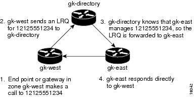
The following example shows how this command is used to simplify configuration by selecting one gatekeeper as the directory gatekeeper. Refer to Figure 5.
Figure 5 Example Scenario with Directory Gatekeeper and Two Remote Gatekeepers
Configuration on gk-directory
On the directory gatekeeper called gk-directory, identify all the prefixes for all the gatekeepers in your administrative domain:
zone local gk-directory cisco.com
zone remote gk-west cisco.com 172.16.1.1
zone remote gk-east cisco.com 172.16.2.1zone prefix gk-west 1408.......zone prefix gk-west 1415.......zone prefix gk-west 1213.......zone prefix gk-west 1650.......zone prefix gk-east 1212.......zone prefix gk-east 1617.......lrq forward-queriesConfiguration on gk-west
On the gatekeeper called gk-west, configure all the locally managed prefixes for that gatekeeper:
zone local gk-west cisco.comzone remote gk-directory cisco.com 172.16.2.3zone prefix gk-west 1408.......zone prefix gk-west 1415.......zone prefix gk-west 1213.......zone prefix gk-west 1650.......zone prefix gk-directory *Configuration on gk-east
On the gatekeeper called gk-east, configure all the locally managed prefixes for that gatekeeper:
zone local gk-east cisco.comzone remote gk-directory cisco.com 172.16.2.3zone prefix gk-east 1212.......zone prefix gk-east 1617.......zone prefix gk-directory *Now when an endpoint or gateway in zone gk-west makes a call to 12125551234, gk-west will send an LRQ for that E.164 address to gk-directory, which forwards the LRQ to gk-east. Gatekeeper gk-east responds directly to gk-west.
Related Commands
lrq reject-unknown-prefix
Enables the gatekeeper to reject all LRQs for zone prefixes that are not configured.
lrq reject-unknown-prefix
To enable the gatekeeper to reject all Location Requests (LRQs) for zone prefixes that are not configured, use the lrq reject-unknown-prefix command in gatekeeper configuration mode. To reenable the gatekeeper to accept and process all incoming LRQs, use the no form of this command.
lrq reject-unknown-prefix
no lrq reject-unknown-prefix
Syntax Description
This command has no arguments or keywords.
Defaults
The gatekeeper accepts and processes all incoming LRQs.
Command Modes
Gatekeeper configuration
Command History
11.3(6)NA2
This command was introduced on the Cisco 2500 and 3600 series routers.
12.0(3)T
This command was integrated into Cisco IOS Release 12.0(3)T.
Usage Guidelines
Use the lrq reject-unknown-prefix command to configure the gatekeeper to reject any incoming LRQs for a destination E.164 address that does not match any of the configured zone prefixes.
Whether or not you enable the lrq reject-unknown-prefix command, the following is true when the E.164 address matches a zone prefix:
•
•
If you do not enable the lrq reject-unknown-prefix command and the target address does not match any known local or remote prefix, the default behavior is to attempt to service the call using one of the local zones. If this default behavior is not suitable for your site, configure the lrq reject-unknown-prefix command on your router to force the gatekeeper to reject such requests.
Examples
Consider the following gatekeeper configuration:
zone local gk408 cisco.comzone local gk415 cisco.comzone prefix gk408 1408.......zone prefix gk415 1415.......lrq reject-unknown-prefixIn this sample configuration, the gatekeeper is configured to manage two zones. One zone contains gateways with interfaces in the 408 area code, and the second zone contains gateways in the 415 area code. Then using the zone prefix command, the gatekeeper is configured with the appropriate prefixes so that calls to those area codes hop off in the optimal zone.
Now say some other zone has been erroneously configured to route calls to the 212 area code to this gatekeeper. When the LRQ for a number in the 212 area code arrives at this gatekeeper, the gatekeeper fails to match the area code, and the LRQ is rejected.
If this was your only site that had any gateways in it and you wanted your other sites to route all calls that require gateways to this gatekeeper, you can undo the lrq reject-unknown-prefix command by simply using the no lrq reject-unknown-prefix command.Now when the gatekeeper receives an LRQ for the address 12125551234, it will attempt to find an appropriate gateway in either one of the zones gk408 or gk415 to service the call.
Related Commands
lrq forward-queries
Enables a gatekeeper to forward LRQs that contain E.164 addresses that match zone prefixes controlled by remote gatekeepers.
lrq timeout blast window
To configure the timeout window for use when sending multiple Location Requests (LRQs) (either sequentially or simultaneously), use the lrq timeout blast window command in gatekeeper configuration mode. To return to the default value, use the no form of this command.
lrq timeout blast window seconds
no lrq timeout blast window
Syntax Description
Defaults
By default, the duration of the window is 6 seconds.
Command Modes
Gatekeeper configuration
Command History
12.1(2)T
This command was introduced on the Cisco 2500, 2600, 3600, and 7200 series routers and on the Cisco MC3810 multiservice concentrator.
Examples
The following example sets the window to 3 seconds:
lrq timeout blast window 3Related Commands
gatekeeper gw-type-prefix
Sets the gatekeepers responsible for each technology prefix.
zone prefix
Adds a prefix to a gatekeeper's zone list.
lrq timeout seq delay
To configure the delay for use when sending Location Requests (LRQs) sequentially, use the lrq timeout seq delay command in gatekeeper configuration mode. To return to the default value, use this no form of the command.
lrq timeout seq delay value
no lrq timeout seq delay
Syntax Description
value
The duration of the delay, in 100 millisecond units. Possible values are 1 through 10. The default is 5 (500 ms or 0.5 seconds).
Defaults
By default, the duration of the window is five 100 millisecond units (500 ms or 0.5 seconds)
Command Modes
Gatekeeper configuration
Command History
12.1(2)T
This command was introduced on the Cisco 2500, 2600, 3600, and 7200 series routers, and on the Cisco MC3810 multiservice concentrator.
Examples
The following example sets the window to 300 milliseconds:
lrq timeout seq delay 3Related Commands
gatekeeper gw-type-prefix
Sets the gatekeepers responsible for each technology prefix.
zone prefix
Adds a prefix to a gatekeeper's zone list.
max-conn
To specify the maximum number of allowed connections for a particular Voice over IP (VoIP) or POTS dial peer, use the max-conn command in dial-peer configuration mode. To set an unlimited number of connections for this dial peer, use the no form of this command.
max-conn number
no max-conn
Syntax Description
number
Specifies the maximum number of connections for this dial peer. Valid values for this field are 1 to 2,147,483,647.
Defaults
The no form of this command is the default, meaning an unlimited number of connections.
Command Modes
Dial-peer configuration
Command History
Usage Guidelines
This command applies to both VoIP and POTS dial peers. Use the max-conn command to define the maximum number of connections used simultaneously on the Cisco AS5300 universal access server to send fax-mail.
This command applies to off-ramp store and forward fax functions.
Examples
The following example configures the maximum number of connections for VoIP dial peer 10 as 5:
dial-peer voice 10 voipmax-conn 5Related Commands
mta receive maximum-recipients
Specifies the maximum recipients for all SMTP connections.
max-connection
To set the maximum number of simultaneous connections to be used for communication with a settlement provider, use the max-connection command in settlement configuration mode. To reset to the default value of this command, use the no form of this command.
max-connection number
no max-connection number
Syntax Description
Defaults
The default is 10 connections.
Command Modes
Settlement configuration
Command History
Examples
The following command sets the maximum number of simultaneous connections to 10:
settlement 0max-connection 10Related Commands
max-forwards
To set the maximum number of proxy or redirect servers that can forward the request, use the max-forwards command in the SIP user agent configuration mode. To reset the default value, use the no form of this command.
max-forwards number
no max-forwards
Syntax Description
Defaults
The default number of hops is 6.
Command Modes
SIP user agent configuration
Command History
12.1(3)T
This command was introduced on the Cisco 2600 and Cisco 3600 series routers and on the Cisco AS5300 universal access server.
Usage Guidelines
To reset this command to the default value, you can also use the default command.
Examples
The following is an example of forwarding requests to proxy or redirect servers:
sip-uamax-forwards 2max-redirects
To set the maximum number of redirect servers that the user agent allows, use the max-redirects command in dial-peer configuration mode. To reset the default value, use the no form of this command.
max-redirects number
no max-redirects
Syntax Description
Maximum number of redirect servers that a call can traverse. Possible values are 1 through 10.
Defaults
The default number of redirects is 1.
Command Modes
Dial-peer configuration
Command History
12.1(1)T
This command was introduced on the Cisco 2600 and Cisco 3600 series routers and on the Cisco AS5300 universal access server.
Examples
The following is an example of setting the maximum number of redirect servers that the user agent allows:
dial-peer voice 102 voipmax-redirects 2Related Commands
dial-peer voice
Enters dial-peer configuration mode and specifies the method of voice-related encapsulation.
mdn
To request that a message disposition notice (MDN) be generated when the message is processed ("opened"), use the mdn command in dial-peer configuration mode. To restore the default value, use the no form of this command.
mdn
no mdn
Syntax Description
This command has no arguments or keywords.
Defaults
Disabled
Command Modes
Dial-peer configuration
Command History
12.0(4)XJ
This command was introduced on the Cisco AS5300 universal access router.
12.1(1)T
This command was integrated into Cisco IOS Release 12.1(1)T.
Usage Guidelines
Message disposition notification is an e-mail message that is generated and sent to the sender when the message is opened by the receiver. Use the mdn command to request that an e-mail response message be sent to the sender when the e-mail that contains the fax TIFF image has been opened.
This command applies to on-ramp store and forward fax functions.
Examples
The following example requests that a message disposition notice be generated by the recipient:
dial-peer voice 10 mmoipmdnRelated Commands
mta receive generate-mdn
Specifies that the off-ramp gateway process a response MDN from an SMTP server.
mta send return-receipt-to
Specifies the address where MDNs are sent.
mgcp
To allocate resources for the media gateway control protocol (MGCP) and start the MGCP daemon, use the mgcp command in global configuration mode. To terminate all calls, release all allocated resources, and stop the MGCP daemon, use the no form of this command.
mgcp [port]
no mgcp
Syntax Description
port
(Optional) Specifies a UDP port for the MGCP gateway. Valid values are 1025 through 65,535. If no port is specified, the command defaults to UDP port 2427.
Defaults
No default behavior or values.
Command Modes
Global configuration
Command History
Usage Guidelines
Once you start the MGCP daemon using the mgcp command, you can suspend it (for example, for maintenance) by using the mgcp block-newcalls command. When you are ready to resume normal MGCP operations, use the no mgcp block-newcalls command. Use the no mgcp command only if you intend to terminate all MGCP applications and protocols.
When the MGCP daemon is not active, all MGCP messages are ignored.
Examples
The following example shows how to initiate the MGCP daemon:
mgcpRelated Commands
mgcp block-newcalls
To block new calls while maintaining existing calls, use the mgcp block-newcalls command in global configuration mode. To resume media gateway control protocol (MGCP) operation, use the no form of this command.
mgcp block-newcalls
no mgcp block-newcalls
Syntax Description
This command has no arguments or keywords.
Defaults
No default behavior or values.
Command Modes
Global configuration
Command History
Usage Guidelines
This command is valid only if the mgcp command is enabled.
Once you issue this command, all requests for new connections (CreateConnection requests) are denied. All existing calls will be maintained until participants terminate them or you use the no mgcp command. When the last active call is terminated, the MGCP daemon will be terminated and all resources allocated to it will be released. The no mgcp block-newcalls command returns the router to normal MGCP operations.
Examples
The following example shows how to prevent the gateway from receiving new calls:
mgcp block-newcallsRelated Commands
mgcp call-agent
To configure the call agent (media gateway controller) address, use the mgcp call-agent command in global configuration mode. To unconfigure the call agent address, use the no form of this command.
mgcp call-agent {ip-address | host-name} [port] [service-type type]
no mgcp call-agent
Syntax Description
Defaults
MGCP service-type
Command Modes
Global configuration
Command History
12.1(1)T
This command was introduced for the Cisco AS5300 universal access server.
12.1(3)T
The service-type type option was added.
Usage Guidelines
Use this command on any platform and media gateway.
If you do not specify a UDP port from the command line, media gateway control protocol (MGCP) will use 2427 as the default call agent UDP port.
When service-type is set to mgcp, the call agent processes the Restart in Progress (RSIP) error messages sent by the gateway. When service-type is sent to sgcp, the call agent ignores the RSIP messages.
Examples
The following examples illustrate several formats for specifying the call agent (use any one of these formats):
mgcp call-agent 209.165.200.225 service-type sgcpmgcp call-agent 209.165.200.225 5530 service-type mgcpmgcp call-agent igloo service-type sgcpmgcp call-agent igloo 2009 service-type mgcpRelated Commands
mgcp codec
To select the default codec type and its optional packetization period value, use the mgcp codec command in global configuration mode. To set the parameters to their default values, use the no form of this command.
mgcp codec type [packetization-period value]
no mgcp codec
Syntax Description
Defaults
G711ulaw
Command Modes
Global configuration
Command History
Examples
This example shows how to specify the default codec type:
mgcp codec g711alawThe following example specifies the codec type and sets the packetization period:
mgcp codec g729r8 packetization-period 150Related Commands
mgcp default-package
To configure the default package capability type for the media gateway, use the mgcp default-package command in global configuration mode. This command does not support a no form. To change the default package, use the mgcp default-package command with a different, actively supported package.
Residential Gateways
mgcp default-package {line-package | dtmf-package | gm-package}
Trunking Gateways
mgcp default-package {as-package | dtmf-package | gm-package | rtp-package | trunk-package}
Syntax Description
as-package
Announcement server package.
dtmf-package
DTMF package.
gm-package
Generic media package.
line-package
Line package.
rtp-package
RTP package.
trunk-package
Trunk package.
Defaults
For residential gateways (RGWs): line-package
For trunking gateways (TGWs): trunk-package
Command Modes
Global configuration
Command History
Usage Guidelines
This command is helpful when the Media Gateway Controller does not provide the package capability to be used for the given connection.
Before selecting a package as the default, use the show mgcp command to ensure that the package is actively supported. If the package you want does not appear in the display, use the mgcp package-capability command to add the package to the supported list.
If only one package is actively supported, it becomes the default package.
Examples
The following example shows how to set the default package:
mgcp default-package as-package! The announcement server package type will be the new default package type.Related Commands
mgcp
Starts the MGCP daemon.
mgcp package-capability
Includes a specific MGCP package that is supported by the gateway.
mgcp dtmf-relay
To ensure accurate forwarding of digits on compressed codecs, use the mgcp dtmf-relay command in controller configuration mode. To disable this process for noncompressed codecs, use the no form of this command.
mgcp dtmf-relay {codec | low-bit-rate} mode {cisco | out-of-band}
no mgcp dtmf-relay
Syntax Description
Defaults
Non compressed codecs are disabled.
Command Modes
Controller configuration
Command History
Usage Guidelines
Use this command to access an announcement server or a voice mail server that does not have the capability to decode RTP packets containing DTMF digits. When the mgcp dtmf-relay command is active, the DTMF digits are removed from the voice stream and carried by FRF.11 so that the server can decode the digits.
Examples
The following example shows how to remove the DTMF tone from the voice stream and send FRF.11 with a special payload for the DTMF digits:
mgcp dtmf-relay codec mode ciscoRelated Commands
mgcp ip-tos
To enable or disable the IP type of service (ToS) for MGCP-controlled connections, use the mgcp ip-tos command in global configuration mode. To set the parameters to their default values, use the no form of this command.
mgcp ip-tos {high-reliability | high-throughput | low-cost | low-delay | precedence value}
no mgcp ip-tos {high-reliability | high-throughput | low-cost | low-delay | precedence value}
Syntax Description
Defaults
Services disabled; precedence is 3.
Command Modes
Global configuration
Command History
Usage Guidelines
Only one of the high-reliability, high-throughput, low-cost, or low-delay parameters can be enabled at any given time. Enabling one parameter disables any other that was active. Enabling one parameter has no effect on the precedence parameter. When you configure a new value for the precedence parameter, the old value is erased.
The no form of the mgcp ip-tos command disables the first four parameters and sets the precedence parameter back to 3.
Examples
In the following example, activating the low-delay keyword disables the other three parameters.
mgcp ip-tos high-reliabilitymgcp ip-tos high-throughputmgcp ip-tos low-costmgcp ip-tos low-delaymgcp ip-tos precedence 4Related Commands
mgcp max-waiting-delay
To specify the media gateway control protocol (MGCP) maximum waiting delay (MWD), use the mgcp max-waiting-delay command in global configuration mode. To restore the default value, use the no form of this command.
mgcp max-waiting-delay milliseconds
no mgcp max-waiting-delay
Syntax Description
milliseconds
The number of milliseconds to wait after restart. The valid range is 0 to 600,000 milliseconds (600 seconds).
Defaults
3000 milliseconds
Command Modes
Global configuration
Command History
Usage Guidelines
Use the maximum waiting delay to send out an RSIP message to the call agent with the restart method. This command helps prevent traffic bottlenecks caused by MGCP gateways all trying to connect at the same time after a restart.
Examples
The following example shows how to set the MGCP maximum waiting delay to 600 milliseconds:
mgcp max-waiting-delay 600Related Commands
mgcp
Starts the MGCP daemon.
mgcp restart-delay
Configures the graceful tear down method sent in the RSIP message.
mgcp modem passthru
To enable the gateway to send and receive modem and fax data, use the mgcp modem passthru command in controller configuration mode. To disable support for modem and fax data, use the no form of this command.
mgcp modem passthru {cisco | ca}
no mgcp modem passthru
Syntax Description
Defaults
ca
Command Modes
Controller configuration
Command History
Usage Guidelines
When the cisco keyword is activated and the gateway detects a modem/fax tone, the gateway switches the codec to G.711 then sends the analog data to a remote gateway. The remote gateway also switches the codec on its side of the call to G.711 to allow the analog data to pass through.
When the ca keyword is activated and the gateway detects a modem/fax tone, the gateway alerts the call agent to switch the codec to G.711 to allow the analog data to pass through. The call agent must send an MDCX signal to the G.711 codec for successful data pass-through.
Examples
The following example configures a gateway to send and receive modem or fax data:
mgcp modem passthru ciscoRelated Commands
mgcp package-capability
To specify a media gateway control protocol (MGCP) package capability for a gateway, use the mgcp package-capability command in global configuration mode. To remove a specific MGCP package capability from the list of capabilities, use the no form of this command.
All Residential Gateways
mgcp package-capability {line-package | dtmf-package | gm-package | rtp-package}
no mgcp package-capability {line-package | dtmf-package | gm-package | rtp-package}
Cisco AS5300 Universal Access Server
mgcp package-capability {trunk-package | dtmf-package | gm-package | rtp-package | as-package | script-package}
no mgcp package-capability {trunk-package | dtmf-package | gm-package | rtp-package | as-package | script-package}
All Other Trunking Gateways
mgcp package-capability {trunk-package | dtmf-package | gm-package | rtp-package | as-package}
no mgcp package-capability {trunk-package | dtmf-package | gm-package | rtp-package | as-package}
Syntax Description
Defaults
For all residential gateways (RGWs): line-package
For all trunking gateways (TGWs): trunk-package
Command Modes
Global configuration
Command History
Usage Guidelines
Select packages that are supported by your call agent. Events specified in the MGCP messages from the call agent must belong to one of the supported packages. Otherwise, the connection requests are refused by the media gateway.
Use this command before specifying a default package using the mgcp default-package command. Specify at least one package to have a default.
Enter each package as a separate command.
Examples
The following example shows how to specify an MGCP package capability for a gateway:
mgcp package-capability trunk-packagemgcp package-capability dtmf-packagemgcp package-capability script-packagemgcp default-package trunk-packageRelated Commands
mgcp
Starts the MGCP daemon.
mgcp default-package
Configures the default package capability type for the media gateway.
mgcp playout
To tune the jitter buffer packet size attempted for MGCP-controlled connections, use the mgcp playout command in global configuration mode. To restore the default value, use the no form of this command.
mgcp playout {adaptive init-value min-value max-value | fixed init-value}
no mgcp playout {adaptive | fixed}
Syntax Description
Defaults
adaptive 60 4 200
No default for fixed.
Command Modes
Global configuration
Command History
Examples
The following example illustrates a jitter buffer configuration with an initial playout of 100, a minimum buffer size of 50, and a maximum buffer size of 150:
mgcp playout adaptive 100 50 150The following example illustrates setting the jitter buffer to a fixed playout of 120:
mgcp playout fixed 120Related Commands
mgcp quality-threshold
To set the jitter buffer size threshold, latency threshold, and packet-loss threshold parameters, use the mgcp quality-threshold command in global configuration mode. To restore the default parameter values, use the no form of this command.
mgcp quality-threshold {hwm-jitter-buffer value | hwm-latency value | hwm-packet-loss value | lwm-jitter-buffer value | lwm-latency value | lwm-packet-loss value}
no mgcp quality-threshold {hwm-jitter-buffer | hwm-latency | hwm-packet-loss | lwm-jitter-buffer | lwm-latency | lwm-packet-loss}
Syntax Description
Defaults
The voice quality parameter defaults are (in milliseconds): hwm-jitter-buffer 150, hwm-latency 300, hwm-packet-loss 10,000, lwm-jitter-buffer 30, lwm-latency 150, and lwm-packet-loss 1000.
Command Modes
Global configuration
Command History
Usage Guidelines
The following parameters impact the quality of voice calls:
•
•
•
For good voice quality, the system should perform below the lwm values. As the values go higher, voice quality degrades. The system generates a report when the values go above the hwm levels. Set the hwm and lwm values sufficiently apart so that you receive reports on poor performance, but not so close together that you receive too much feedback.
Enter each parameter as a separate command.
Examples
The following example shows how the different parameters can be set to new values:
mgcp quality-threshold hwm-jitter-buffer 100mgcp quality-threshold hwm-latency 250mgcp quality-threshold hwm-packet-loss 5000mgcp quality-threshold lwm-jitter-buffer 50mgcp quality-threshold lwm-latency 200mgcp quality-threshold lwm-packet-loss 20Related Commands
mgcp request retries
To specify the number of times to retry sending the mgcp command, use the mgcp request retries command in global configuration mode. To restore the default value, use the no form of this command.
mgcp request retries count
no mgcp request retries
Syntax Description
count
Specifies the number of times a Notify message is resent to the Call Agent before the request is dropped. The valid range is 1 to 10.
Defaults
Three times
Command Modes
Global configuration
Command History
Usage Guidelines
This command applies to a trunking gateway.
Examples
The following example shows that the system will try to send the mgcp command 10 times before dropping the request:
mgcp request retries 10Related Commands
mgcp
Starts the MGCP daemon.
mgcp request timeout
Specifies how long the system waits for a response to a request.
mgcp request timeout
To specify how long the system waits for a response to a request, use the mgcp request timeout command in global configuration mode. To restore the default value, use the no form of this command.
mgcp request timeout timeout
no mgcp request timeout
Syntax Description
timeout
Specifies the number of milliseconds to wait for a response to a request. The valid range is 1 to 10,000 (10 seconds).
Defaults
500 milliseconds
Command Modes
Global configuration
Command History
Examples
The following example configures the system to wait 40 milliseconds for a reply to a request:
mgcp request timeout 40Related Commands
mgcp
Starts the MGCP daemon.
mgcp request retries
Specifies the number of times to retry sending the mgcp command.
mgcp restart-delay
To select the delay value sent in the Restart in Progress (RSIP) graceful tear down, use the mgcp restart-delay command in global configuration mode. To restore the default value, use the no form of this command.
mgcp restart-delay seconds
no mgcp restart-delay
Syntax Description
Defaults
Zero (0) seconds
Command Modes
Global configuration
Command History
Usage Guidelines
Use the restart value to send a RSIP message that indicates when the connection in the gateway will be torn down.
Examples
The following example sets the restart delay to 30 seconds:
mgcp restart-delay 30Related Commands
mgcp
Starts the MGCP daemon.
mgcp max-waiting-delay
Specifies the MGCP MWD after a restart.
mgcp sdp simple
To initiate a subset of the SDP protocol, use the mgcp sdp simple command in controller configuration mode. To return to the full set of SDP protocol fields, use the no form of this command.
mgcp sdp simple
no mgcp sdp simple
Syntax Description
This command has no arguments or keywords.
Defaults
no mgcp sdp simple
Command Modes
Controller configuration
Command History
Usage Guidelines
When the mgcp sdp simple command is enabled, the gateway will not generate three SDP fields: time, session name, and other (username, session id, sdp version, network type, address type, or address). Certain call agents require this modified SDP protocol to send data through the network.
Examples
The following example configures the modified SDP protocol:
mgcp sdp simpleRelated Commands
mgcp vad
To set the default VAD parameter for the media gateway control protocol (MGCP), use the mgcp vad command in global configuration mode. To disable the VAD parameter, use the no form of this command.
mgcp vad
no mgcp vad
Syntax Description
This command has no arguments or keywords.
Defaults
Disabled
Command Modes
Global configuration
Command History
Usage Guidelines
Use the MGCP VAD parameter to tell the MGCP gateway to turn silence suppression on or off.
Examples
The following example turns silence suppression on:
mgcp vadRelated Commands
microcode reload controller
To reload the firmware and FPGA from the command-line interface (CLI) without reloading the Cisco IOS image, use the microcode reload controller command in privileged EXEC mode.
microcode reload controller {t1 | e1} {x/y}
Syntax Description
Defaults
No microcode reload activity is initiated.
Command Modes
Privileged EXEC
Command History
12.1(2)XH
This command was introduced on the Cisco 2600 and Cisco 3600 series routers.
Usage Guidelines
Configurations such as channel groups, TDM connections, and loopbacks and so on in the running configuration are restored after this command is issued. If either of the controller ports on the WIC is in a looped state before this command is issued, the looped condition is dropped. You have to reinitiate the loopbacks from the remote end by doing "no loop" and "loop remote" from the controller configuration. If the BERT test is running, that test will be aborted for the microcode reload.
mmoip aaa global-password
To define a password to be used with CiscoSecure for Windows NT when using store and forward fax, use the mmoip aaa global-password command in global configuration mode. To restore the default state, use the no form of this command.
mmoip aaa global-password password
no mmoip aaa global-password password
Syntax Description
password
Character string used to define the password for CiscoSecure for Windows NT to be used with store and forward fax. The maximum length is 64 alphanumeric characters.
Defaults
No password is defined.
Command Modes
Global configuration
Command History
12.0(4)XJ
This command was introduced on the Cisco AS5300 universal access server.
12.1(1)T
This command was integrated into Cisco IOS Release 12.1(1)T.
Usage Guidelines
CiscoSecure for Windows NT might require a separate password in order to complete authentication, no matter what security protocol you use. This command defines the password to be used with CiscoSecure for Windows NT. All records on the Windows NT server use this defined password.
This command applies to on-ramp store and forward fax functions when using a modem card. It is not used with voice feature cards.
Examples
The following example defines a password (password) when CiscoSecure for Windows NT is used with store and forward fax:
mmoip aaa global-password passwordmmoip aaa method fax accounting
To define the name of the method list to be used for authentication, authorization, and accounting (AAA) accounting with store and forward fax, use the mmoip aaa method fax accounting command in global configuration mode. To restore the default value, use the no form of this command.
mmoip aaa method fax accounting method-list-name
no mmoip aaa method fax accounting method-list-name
Syntax Description
method-list-name
Character string used to name a list of accounting methods to be used with store and forward fax.
Defaults
No AAA accounting method list is defined.
Command Modes
Global configuration
Command History
12.0(4)XJ
This command was introduced on the Cisco AS5300 universal access server.
12.1(1)T
This command was integrated into Cisco IOS Release 12.1(1)T.
Usage Guidelines
This command defines the name of the AAA accounting method list to be used with store and forward fax. The method list itself, which defines the type of accounting services provided for store and forward fax, is defined using the aaa accounting global configuration command. Unlike standard AAA (where each defined method list can be applied to specific interfaces and lines), the AAA accounting method lists used in store and forward fax are applied globally on the Cisco AS5300 universal access server.
After the accounting method lists have been defined, they are enabled by using the mmoip aaa receive-accounting enable command.
This command applies to both on-ramp and off-ramp store and forward fax functions when using a modem card. It is not used with voice feature cards.
Examples
The following example defines a AAA accounting method list (called sherman) to be used with store and forward fax:
aaa new-modelmmoip aaa method fax accounting shermanRelated Commands
mmoip aaa method fax authentication
To define the name of the method list to be used for authentication, authorization, and accounting (AAA) authentication with store and forward fax, use the mmoip aaa method fax authentication command in global configuration mode. To restore the default state, use the no form of this command.
mmoip aaa method fax authentication method-list-name
no mmoip aaa method fax authentication method-list-name
Syntax Description
method-list-name
Character string used to name a list of authentication methods to be used with store and forward fax.
Defaults
No AAA authentication method list is defined.
Command Modes
Global configuration
Command History
12.0(4)XJ
This command was introduced on the Cisco AS5300 universal access server.
12.1(1)T
This command was integrated into Cisco IOS Release 12.1(1)T.
Usage Guidelines
This command defines the name of the AAA authentication method list to be used with store and forward fax. The method list itself, which defines the type of authentication services provided for store and forward fax, is defined using the aaa authentication global configuration command. Unlike standard AAA (where each defined method list can be applied to specific interfaces and lines), AAA authentication method lists used with store and forward fax are applied globally on the Cisco AS5300 universal access server.
After the authentication method lists have been defined, they are enabled by using the mmoip aaa receive-authentication enable command.
This command applies to both on-ramp and off-ramp store and forward fax functions.
Examples
The following example defines a AAA authentication method list (called xyz) to be used with store and forward fax:
aaa new-modelmmoip aaa method fax authentication xyzRelated Commands
mmoip aaa receive-accounting enable
To enable on-ramp authentication, authorization, and accounting (AAA) accounting services, use the mmoip aaa receive-accounting enable command in global configuration mode. To restore the default state, use the no form of this command.
mmoip aaa receive-accounting enable
no mmoip aaa receive-accounting enable
Syntax Description
This command has no arguments or keywords.
Defaults
Disabled
Command Modes
Global configuration
Command History
12.0(4)XJ
This command was introduced on the Cisco AS5300 universal access server.
12.1(1T)
This command was integrated into Cisco IOS Release 12.1(1)T.
Usage Guidelines
This command enables AAA accounting services if a AAA accounting method list has been defined using both the aaa accounting command and the mmoip aaa method fax accounting command.
This command applies to on-ramp store and forward fax functions.
Examples
The following example enables a AAA accounting method list (called xyz) to be used with inbound store and forward fax. In this example, store and forward fax is being configured to track start and stop connection accounting records.
aaa new-modelmmoip aaa method fax accounting xyzaaa accounting connection sherman stop-only radiusmmoip aaa receive-accounting enableRelated Commands
mmoip aaa receive-authentication enable
To enable on-ramp authentication, authorization, and accounting (AAA) authentication services, use the mmoip aaa receive-authentication enable command in global configuration mode. To restore the default state, use the no form of this command.
mmoip aaa receive-authentication enable
no mmoip aaa receive-authentication enable
Syntax Description
This command has no arguments or keywords.
Defaults
Disabled
Command Modes
Global configuration
Command History
12.0(4)XJ
This command was introduced.
12.1(1)T
This command was integrated into Cisco IOS Release 12.1(1)T.
Usage Guidelines
This command enables AAA authentication services if an AAA authentication method list has been defined using both the aaa authentication command and the mmoip aaa method fax authentication command.
This command applies to on-ramp store and forward fax functions.
Examples
The following example enables a AAA authentication method list (called xyz) to be used with inbound store and forward fax. In this example, RADIUS authentication (and if the RADIUS server fails, then local authentication) is being configured for store and forward fax.
aaa new-modelmmoip aaa method fax authentication xyzaaa authentication login peabody radius localmmoip aaa receive-authentication enableRelated Commands
mmoip aaa receive-id primary
To specify the primary location where the authentication, authorization, and accounting (AAA) protocol retrieves its account identification information for on-ramp faxing, use the mmoip aaa receive-id primary command in global configuration mode. To restore the default state, which means that the account identification source is undefined, use the no form of this command.
mmoip aaa receive-id primary {ani | dnis | gateway | redialer-id | redialer-dnis}
no mmoip aaa receive-id primary {ani | dnis | gateway | redialer-id | redialer-dnis}
Syntax Description
Defaults
No account identification source is defined.
Command Modes
Global configuration
Command History
12.0(4)XJ
This command was introduced on the Cisco AS5300 universal access server.
12.1(1)T
This command was integrated into Cisco IOS Release 12.1(1)T.
Usage Guidelines
Normally, when AAA is being used for simple user authentication, AAA uses the username information defined in the user profile for authentication. With store and forward fax, you can specify that the ANI, DNIS, gateway ID, redialer ID, or redialer DNIS be used to identify the user for authentication. This command defines what AAA uses for the primary identifier for inbound or on-ramp user authentication with store and forward fax.
Store and forward fax allows you to define either a primary or a secondary identifier. (You configure the secondary identifier using the mmoip aaa receive-id secondary command.)
AAA does not use these methods sequentially—meaning that if the primary identifier is defined and AAA cannot authenticate the primary identifier information, it will not use the secondary identifier for authentication. Authentication simply fails.
Defining only the secondary identifier enables you to service two different scenarios simultaneously—for example, if you are offering fax services to two different companies, one of which uses redialers and the other does not. In this case, configure the mmoip aaa receive-id primary command to use the redialer DNIS, and configure the mmoip aaa receive-id secondary command to use ANI. With this configuration, when a user dials in and the redialer DNIS is not null, the redialer DNIS is used as the authentication identifier. If a user dials in and the redialer DNIS is null, ANI is used as the authentication identifier.
This command applies to on-ramp store and forward fax functions.
Examples
The following example defines the DNIS captured by the redialer as the AAA authentication identifier for store and forward fax:
aaa new-modelmmoip aaa receive-id primary redialer-dnisRelated Commands
mmoip aaa receive-id secondary
To specify the secondary location where the authentication, authorization, and accounting (AAA) protocol retrieves its account identification information for on-ramp faxing if the primary identifier has not been defined, use the mmoip aaa receive-id secondary command in global configuration mode. To restore the default state, which means that the account identification source is undefined, use the no form of this command.
mmoip aaa receive-id secondary {ani | dnis | gateway | redialer-id | redialer-dnis}
no mmoip aaa receive-id secondary {ani | dnis | gateway | redialer-id | redialer-dnis}
Syntax Description
Defaults
No account identification source is defined.
Command Modes
Global configuration
Command History
12.0(4)XJ
This command was introduced on the Cisco AS5300 universal access server.
12.1(1)T
This command was integrated into Cisco IOS Release 12.1(1)T.
Usage Guidelines
Normally, when AAA is being used for simple user authentication, AAA uses the username information defined in the user profile for authentication. With store and forward fax, you can specify that the ANI, DNIS, gateway ID, redialer DNIS, or redialer ID be used to identify the user for authentication. This command defines what AAA uses for the secondary identifier for inbound or on-ramp user authentication with store and forward fax if the primary identifier has not been defined.
Store and forward fax allows you to define either a primary or a secondary identifier. (You configure the primary identifier using the mmoip aaa receive-id primary command.)
AAA does not use these methods sequentially—meaning that if the primary identifier is defined and AAA cannot match the primary identifier information, it will not use the secondary identifier for authentication. Authentication simply fails.
Defining only the secondary identifier enables you to service two different scenarios simultaneously—for example, if you are offering fax services to two different companies, one of which uses redialers and the other does not. In this case, configure the mmoip aaa receive-id primary command to use the redialer DNIS, and configure the mmoip aaa receive-id secondary command to use ANI. With this configuration, when a user dials in and the redialer DNIS is not null, the redialer DNIS is used as the authentication identifier. If a user dials in and the redialer DNIS is null, ANI is used as the authentication identifier.
This command applies to on-ramp store and forward fax functions.
Examples
The following example defines the DNIS captured by the redialer as the secondary AAA authentication identifier for store and forward fax:
aaa new-modelmmoip aaa receive-id secondary redialer-dnisRelated Commands
mmoip aaa receive-id primary
Specifies the primary location where AAA retrieves its account identification information for on-ramp faxing.
mmoip aaa send-accounting enable
To enable off-ramp authentication, authorization, and accounting (AAA) accounting services, use the mmoip aaa send-accounting enable command in global configuration mode. To restore the default state, use the no form of this command.
mmoip aaa send-accounting enable
no mmoip aaa send-accounting enable
Syntax Description
This command has no arguments or keywords.
Defaults
Disabled
Command Modes
Global configuration
Command History
12.0(4)XJ
This command was introduced on the Cisco AS5300 universal access server.
12.1(1)T
This command was integrated into Cisco IOS Release 12.1(1)T.
Usage Guidelines
This command enables AAA accounting services if an AAA accounting method list has been defined using both the aaa accounting command and the mmoip aaa method fax accounting command.
This command applies to off-ramp store and forward fax functions when using a modem card. It is not used with voice feature cards.
Examples
The following example enables an AAA accounting method list (called xyz) to be used with outbound store and forward fax. In this example, store and forward fax is being configured to track start and stop connection accounting records.
aaa new-modelmmoip aaa method fax accounting xyzaaa accounting connection sherman stop-only radiusmmoip aaa send-accounting enableRelated Commands
mmoip aaa send-authentication enable
To enable off-ramp authentication, authorization, and accounting (AAA) authentication services, use the mmoip aaa send-authentication enable command in global configuration mode. To restore the default value, use the no form of this command.
mmoip aaa send-authentication enable
no mmoip aaa send-authentication enable
Syntax Description
This command has no arguments or keywords.
Defaults
Disabled
Command Modes
Global configuration
Command History
12.0(4)XJ
This command was introduced on the Cisco AS5300 universal access server.
12.1(1)T
This command was integrated into Cisco IOS Release 12.1(1)T.
Usage Guidelines
This command enables AAA authentication services if an AAA authentication method list has been defined using both the aaa authentication command and the mmoip aaa method fax authentication command.
This command applies to off-ramp store and forward fax functions.
Examples
The following example enables an AAA authentication method list (called xyz) to be used with outbound store and forward fax. In this example, RADIUS authentication (and if the RADIUS server fails, then local authentication) is being configured for store and forward fax.
aaa new-modelmmoip aaa method fax authentication xyzaaa authentication login peabody radius localmmoip aaa send-authentication enableRelated Commands
mmoip aaa send-id primary
To specify the primary location where the authentication, authorization, and accounting (AAA) protocol retrieves its account identification information for off-ramp faxing, use the mmoip aaa send-id primary command in global configuration mode. To restore the default state, which means that account identification source is undefined, use the no form of this command.
mmoip aaa send-id primary {account-id | envelope-from | envelope-to | gateway}
no mmoip aaa send-id primary {account-id | envelope-from | envelope-to | gateway}
Syntax Description
Defaults
No account identification source is defined.
Command Modes
Global configuration
Command History
12.0(4)XJ
This command was introduced on the Cisco AS5300 universal access server.
12.1(1)T
This command was integrated into Cisco IOS Release 12.1(1)T.
Usage Guidelines
Normally, when AAA is being used for simple user authentication, AAA uses the username information defined in the user profile for authentication. With store and forward fax, you can specify that the account ID, username, or recipient name from the e-mail header information be used to identify the user for authentication. This command defines what AAA uses for the primary identifier for outbound or off-ramp user authentication with store and forward fax.
Store and forward fax allows you to define either a primary or a secondary identifier. (You configure the secondary identifier using the mmoip aaa send-id secondary command.) AAA extracts the authentication identifier information from the defined sources. If the field is blank (meaning undefined), AAA will use the secondary identifier source if configured. The secondary identifier is used only when the primary identifier is null. In this case, when AAA sees that the primary identifier is null, it will check to see if a secondary identifier has been defined and use that value for user authentication.
AAA does not use these methods sequentially—meaning that if the primary identifier is defined and AAA cannot authenticate the primary identifier information, it will not use the secondary identifier for authentication. Authentication simply fails.
When you enable authentication, the on-ramp gateway inserts whatever value you configure for the mmoip aaa receive-id primary command in the X-account ID field of the e-mail header. This X-account ID field contains the value that is used for authentication and accounting by the on-ramp gateway. For example, if the mmoip aaa receive-id primary command is set to gateway, the on-ramp gateway name (for example, hostname.domain-name) is inserted in the X-account ID field of the e-mail header of the fax-mail message.
If you want to use this configured gateway value in the X-account ID field, you must configure the mmoip aaa send-id primary command with the account-id keyword. This particular keyword enables store and forward fax to generate end-to-end authentication and accounting tracking records. If you do not enable authentication on the on-ramp gateway, the X-account ID field is left blank.
This command applies to off-ramp store and forward fax functions.
Examples
The following example defines the recipient name as defined in the envelope-to field of the e-mail header to be used as the AAA authentication identifier for store and forward fax:
aaa new-modelmmoip aaa send-id primary envelope-toRelated Commands
mmoip aaa send-id secondary
To specify the secondary location where the authentication, authorization, and accounting (AAA) protocol retrieves its account identification information for off-ramp faxing, use the mmoip aaa send-id secondary command in global configuration mode. To restore the default state, which means that account identification source is undefined, use the no form of this command.
mmoip aaa send-id secondary {account-id | envelope-from | envelope-to | gateway}
no mmoip aaa send-id secondary {account-id | envelope-from | envelope-to | gateway}
Syntax Description
Defaults
No account identification source is defined.
Command Modes
Global configuration
Command History
12.0(4)XJ
This command was introduced on the Cisco AS5300 universal access server.
12.1(1)T
This command was integrated into Cisco IOS Release 12.1(1)T.
Usage Guidelines
Normally, when AAA is being used for simple user authentication, AAA uses the username information defined in the user profile for authentication. With store and forward fax, you can specify that the account ID, username, or recipient name from the e-mail header information be used to identify the user for authentication. This command defines what AAA uses for the secondary identifier for outbound or off-ramp user authentication with store and forward fax.
Store and forward fax allows you to define either a primary or a secondary identifier. (You configure the primary identifier using the mmoip aaa send-id primary command.) AAA extracts the authentication identifier information from the defined sources. If the field is blank (meaning undefined), AAA will use the secondary identifier source if configured. The secondary identifier is used only when the primary identifier is null. In this case, when AAA sees that the primary identifier is null, it will check to see if a secondary identifier has been defined and use that value for user authentication.
AAA does not use these methods sequentially—meaning that if the primary identifier is defined and AAA cannot match the primary identifier information, it will not use the secondary identifier for authentication. Authentication simply fails.
When you enable authentication, the on-ramp gateway inserts whatever value you configure for the mmoip aaa receive-id secondary command in the X-account ID field of the e-mail header (if store-and-forward uses the defined secondary identifier). This X-account ID field contains the value that is used for authentication and accounting by the on-ramp gateway. For example, if the mmoip aaa receive-id secondary command is set to gateway, the on-ramp gateway name (for example, hostname.domain-name) is inserted in the X-account ID field of the e-mail header of the fax-mail message.
If you want to use this configured gateway value in the X-account ID field, you must configure the mmoip aaa send-id secondary command with the account-id keyword. This particular keyword enables store and forward fax to generate end-to-end authentication and accounting tracking records. If you do not enable authentication on the on-ramp gateway, the X-account ID field is left blank.
This command applies to off-ramp store and forward fax functions.
Examples
The following example defines the recipient name as defined in the envelope-to field of the e-mail header to be used as the AAA authentication identifier for store and forward fax:
aaa new-modelmmoip aaa send-id secondary envelope-toRelated Commands
mode
To set the mode of the T1/E1 controller and enter specific configuration commands for each mode type, use the mode command in controller configuration mode. To restore the default mode of the controller, use the no form of this command.
mode {atm | cas}
no mode {atm | cas}
Syntax Description
Defaults
No mode is configured.
Command Modes
Controller configuration
Command History
11.3(1)MA
This command was introduced on the Cisco MC3810 multiservice concentrator.
Usage Guidelines
This command applies to the Cisco MC3810 multiservice concentrator with the digital voice module (DVM) installed.
When no mode is selected, channel groups and clear channels (data mode) can be created using the channel group and tdm-group commands, respectively.
On the Cisco MC3810 multiservice concentrator, some DS0s are used exclusively for different signaling modes. The DS0 channels have the following limitations when mixing different applications (such as voice and data) on the same network trunk:
•
•
Examples
The following example configures ATM mode on controller T1 0. This is required for Voice over ATM.
controller T1 0mode atmThe following example configures CAS mode on controller T1 1:
controller T1 1mode casRelated Commands
mode ccs
To configure the T1/E1 controller to support common channel signaling (CCS) cross-connect or CCS frame forwarding, use the mode ccs command in controller configuration mode. To disable support for CCS cross-connect or CCS frame forwarding on the controller, use the no form of this command.
mode ccs {cross-connect | frame-forwarding}
no mode ccs {cross-connect | frame-forwarding}
Syntax Description
cross-connect
Enables CCS cross-connect on the controller.
frame-forwarding
Enables CCS frame forwarding on the controller.
Defaults
No CCS mode is configured.
Command Modes
Controller configuration
Command History
Examples
To enable CCS cross-connect on controller T1 1, enter the following commands:
controller T1 1mode ccs cross-connectTo enable CCS frame forwarding on controller T1 1, enter the following commands:
controller T1 1mode ccs frame-forwardingRelated Commands
ccs connect
Configures a CCS connection on an interface configured to support CCS frame forwarding.
modem passthrough (dial-peer)
To configure modem passthrough over VoIP for a specific dial peer, use the modem passthrough command in dial-peer configuration mode. To disable modem passthrough for a specific dial peer, use the no modem passthrough command.
modem passthrough {system | nse [payload-type number] codec {g711ulaw | g711alaw} [redundancy]}
no modem passthrough
Syntax Description
Defaults
Defining system as the method in dial peer points to the voice service Voice over IP (VoIP) configuration default and is intended to simplify gateway configuration. The default is modem passthrough system. As required, the gateway defaults to no modem passthrough.
Command Modes
Dial-peer configuration
Command History
12.1(3)T
This command was introduced for the Cisco AS5300 universal access server.
Usage Guidelines
Use the modem passthrough dial-peer configuration command to configure modem passthrough over VoIP for a specific dial peer. The payload type is an optional parameter for the nse keyword. Use the same payload-type number for both the originating gateway and the terminating gateway. The payload-type number can be set from 96 to 119. If you do not specify the payload-type number, the number defaults to 100.
Use the same codec type for both the originating gateway and the terminating gateway. g711ulaw codec is required for T1, and g711alaw codec is required for E1.
The redundancy keyword is an optional parameter for sending redundant packets for modem traffic.
When the system keyword is enabled, the following parameters are not available: nse, payload-type, codec, and redundancy. The system keyword overrides the configuration for the dial peer, and the values from the global configuration are used.
Examples
The following example shows how modem passthrough over VoIP is configured for a specific dial peer in dial-peer configuration mode:
modem passthrough nse codec g711ulaw redundancyRelated Commands
modem passthrough (voice-service)
To configure modem passthrough over VoIP for the Cisco AS5300 universal access server, use the modem passthrough command in voice-service configuration mode. To disable modem passthrough, use the no form of this command.
modem passthrough nse [payload-type number] codec {g711ulaw | g711alaw}
[redundancy] [maximum-sessions value]no modem passthrough
Syntax Description
Defaults
Disabled
Command Modes
Voice-service configuration
Command History
12.1(3)T
This command was introduced for the Cisco AS5300 universal access server.
Usage Guidelines
Use the modem passthrough command to configure modem passthrough over Voice over IP (VoIP) for the Cisco AS5300 universal access server. The default behavior for the voice service voip command is no modem passthrough.
The payload type is an optional parameter for the nse keyword. Use the same payload-type number for both the originating gateway and the terminating gateway. The payload-type number can be set from 96 to 119. If you do not specify the payload-type number, the number defaults to 100.
Use the same codec type for both the originating gateway and the terminating gateway. g711ulaw codec is required for T1, and g711alaw codec is required for E1.
The redundancy keyword is an optional parameter for sending redundant packets for modem traffic.
The maximum-sessions keyword is an optional parameter for the modem passthrough command. This parameter determines the maximum number of simultaneous modem passthrough sessions. The recommended value for the maximum-sessions keyword is 16. The value can be set from 1 to 26.
When using the voice service voip and modem passthrough nse commands on a terminating gateway to globally set up fax or modem pass-through with NSEs, you must also ensure that each incoming call will be associated with a VoIP dial peer to retrieve the global fax or modem configuration. You associate calls with dial peers by using the incoming called-number command to specify a sequence of digits that incoming calls can match. You can ensure that all calls will match at least one dial peer by using the following commands:
Router(config)# dial-peer voice tag voipRouter(config-dial-peer)# incoming called-number .Examples
The following example shows modem pass-though configuration in voice-service configuration mode for NSE payload type 101 using codec G.711:
modem passthrough nse payload-type 101 codec g711ulaw redundancy maximum-sessions 1Related Commands
mta receive aliases
To specify a host name accepted as a Simple Mail Transfer Protocol (SMTP) alias for off-ramp faxing, use the mta receive aliases command in global configuration mode. To disable this alias, use the no form of this command.
mta receive aliases string
no mta receive aliases string
Syntax Description
Defaults
Enabled with an empty string
Command Modes
Global configuration
Command History
12.0(4)XJ
This command was introduced on the Cisco AS5300 and Cisco AS5800 universal access servers.
12.1(1)T
This command was integrated into Cisco IOS Release 12.1(1)T.
Usage Guidelines
This command creates an accept or reject alias list. The first alias is used by the mailer to identify itself in SMTP banners and when generating its own RFC 822 Received: header.
Note
This command applies to on-ramp store and forward fax functions.
Examples
The following example specifies the host name seattle-fax-offramp.example.com as the alias for the SMTP server:
mta receive aliases seattle-fax-offramp.example.comThe following example specifies the IP address 172.166.0.0 as the alias for the SMTP server:
mta receive aliases [172.16.0.0]Related Commands
mta receive generate-mdn
To specify that the off-ramp gateway process a response message disposition notice (MDN) from a Simple Mail Transfer Protocol (SMTP) server, use the mta receive generate-mdn command in global configuration mode. To disable message delivery notice generation, use the no form of this command.
mta receive generate-mdn
no mta receive generate-mdn
Syntax Description
This command has no arguments or keywords.
Defaults
Disabled
Command Modes
Global configuration
Command History
12.0(4)XJ
This command was introduced on the Cisco AS5300 and Cisco AS5800 universal access servers.
12.1(1)T
This command was integrated into Cisco IOS Release 12.1(1)T.
Usage Guidelines
When message delivery notification is enabled on a sending Cisco AS5300 universal access server, the device inserts a flag in the off-ramp message e-mail header, requesting that the receiving Cisco AS5300 universal access server generate the message delivery notification and return that message to the sender when the e-mail message that contains the fax image is opened. Use the mta receive generate-mdn command to enable the receiving device—the off-ramp gateway—to process the response message delivery notification.
Depending on the configuration, usage, and features of the mailers used at a site, it might be desirable to enable or disable MDN generation. (DSN generation cannot be disabled.)
Specifications for MDN are described in RFC 2298.
This command applies to off-ramp store and forward fax functions.
Examples
The following example enables the receiving device to generate message delivery notices:
mta receive generate-mdnRelated Commands
mta receive maximum-recipients
To specify the maximum number of recipients for all Simple Mail Transfer Protocol (SMTP) connections, use the mta receive maximum-recipients command in global configuration mode. To restore the default value, use the no form of this command.
mta receive maximum-recipients number
no mta receive maximum-recipients
Syntax Description
number
Specifies the maximum number of recipients for all SMTP connections. Valid entries are from 0 to 1024.
Defaults
The default is 0 recipients, meaning that incoming mail messages will not be accepted; therefore, no faxes are sent by the off-ramp gateway.
Command Modes
Global configuration
Command History
12.0(4)XJ
This command was introduced on the Cisco AS5300 and Cisco AS5800 universal access servers.
12.1(1)T
This command was integrated into Cisco IOS Release 12.1(1)T.
Usage Guidelines
This command applies to off-ramp store and forward fax functions.
Note
Use the mta receive maximum-recipients command to configure the maximum number of modems that you want to allocate for fax usage at any one time. You can use this command to limit the resource usage on the gateway. When the value for the number argument is set to 0, no new connections can be established. This is particularly useful when preparing to shut down the system.
Examples
The following example defines 10 as the maximum number of recipients for all SMTP connections:
mta receive maximum-recipients 10Related Commands
mta send mail-from
To specify the mail-from address (also called the RFC 821 envelope-from address or the Return-Path address), use the mta send mail-from command in global configuration mode. To disable this return path information, use the no form of this command.
mta send mail-from {hostname string | username string | username $s$}
no mta send mail-from {hostname string | username string | username $s$}
Syntax Description
Defaults
No default behavior or values.
Command Modes
Global configuration
Command History
12.0(4)XJ
This command was introduced on the Cisco AS5300 and Cisco AS5800 universal access servers.
12.1(1)T
This command was integrated into Cisco IOS Release 12.1(1)T.
Usage Guidelines
Use the mta send mail-from command to designate the sender of the fax TIFF attachment. This value is equivalent to the return path information in an e-mail message.
The postmaster address, configured with the mta send postmaster command, is used if the mail-from address is blank.
This command applies to on-ramp store and forward fax functions.
Examples
The following example specifies that the mail-from username information will be derived from the calling number of the sender:
mta send mail-from username $s$Related Commands
mta send origin-prefix
To add information to the e-mail prefix header, use the mta send origin-prefix command in global configuration mode. To disable the defined string, use the no form of this command.
mta send origin-prefix string
no mta send origin-prefix string
Syntax Description
string
Text string that adds comments to the e-mail prefix header. If this string contains more than one word, the string value should be contained within quotation marks ("abc xyz").
Defaults
Null string
Command Modes
Global configuration
Command History
12.0(4)XJ
This command was introduced on the Cisco AS5300 and Cisco AS5800 universal access servers.
12.1(1)T
This command was integrated into Cisco IOS Release 12.1(1)T.
Usage Guidelines
Normally, the store and forward fax feature provides the slot and port number from which the e-mail came in the e-mail prefix header information. Use this command to append the defined text string to the front of the e-mail prefix header information. This test string is a prefix string that is appended with the modem port and slot number and passed in the originator_comment field of the esmtp_client_engine_open() call. Eventually, this ends up in the received header field of the fax-mail message, for example:
Received (test onramp Santa Cruz slot1 port15) by router-5300.cisco.com for
<test-test@cisco.com> (with Cisco NetWorks); Fri, 25 Dec 1998 001500 -0800
In other words, using the command mta send origin-prefix dog causes the Received header to contain the following information:
Received (dog, slot 3 modem 8) by as5300-sj.example.com....This command applies to on-ramp store and forward fax functions.
Examples
The following example shows how to add information to the e-mail prefix header:
mta send origin-prefix "Cisco-Powered Fax System"Related Commands
mta send postmaster
To define where an e-mail message should be delivered (the mail server postmaster account) if it cannot be delivered to the defined destination, use the mta send postmaster command in global configuration mode. To disable this defined postmaster, use the no form of this command.
mta send postmaster e-mail-address
no mta send postmaster e-mail-address
Syntax Description
e-mail-address
E-mail address that defines where this e-mail message should be delivered (the mail server postmaster account) if it cannot be delivered to the defined destination.
Defaults
No default behavior or values.
Command Modes
Global configuration
Command History
12.0(4)XJ
This command was introduced on the Cisco AS5300 and Cisco AS5800 universal access servers.
12.1(1)T
This command was integrated into Cisco IOS Release 12.1(1)T.
Usage Guidelines
If you have configured the Cisco AS5300 universal access server to generate DSNs and MDNs but you have not configured the sender information (using the mta send mail-from command) or the Simple Mail Transfer Protocol (SMTP) server, DSNs and MDNs are delivered to the e-mail address determined by this command.
The address defined by this command is used as the mta send mail-from address if the evaluated string is blank. An address, such as fax-administrator@example.com, is recommended (where example.com is replaced with your domain name, and fax-administrator is aliased to the person responsible for the operation of the AS5300 universal access server fax functions). At some sites, this may be the same person as the e-mail postmaster, but at most sites this is likely to be a different person and thus should be a different e-mail address.
This command applies to on-ramp store and forward fax functions.
Examples
The following example configures the e-mail address fax-admin@example.com as the sender for all incoming faxes. Thus, any returned DSNs will be delivered to fax-admin@example.com if the mail-from field is otherwise blank.
mta send postmaster fax-admin@example.comRelated Commands
mta send return-receipt-to
To specify the address where message disposition notices (MDNs) are sent, use the mta send return-receipt-to command in global configuration mode. To restore the default value, use the no form of this command.
mta send return-receipt-to {hostname string | username string | username $s$}
no mta send return-receipt-to {hostname string | username string | username $s$}
Syntax Description
Defaults
No default behavior or values.
Command Modes
Global configuration
Command History
12.0(4)XJ
This command was introduced on the Cisco AS5300 and Cisco AS5800 universal access servers.
12.1(1)T
This command was integrated into Cisco IOS Release 12.1(1)T.
Usage Guidelines
Use the mta send return-receipt-to command to define where you want MDNs to be sent after the fax-mail is opened.
Note
Note
This command applies to on-ramp store and forward fax functions.
Examples
The following example configures scoobee as the SMTP mail server to which DSNs are sent:
mta send return-receipt-to hostname server.commta send return-receipt-to username scoobeeRelated Commands
mta send server
To specify a destination mail server or servers, use the mta send server command in global configuration mode. To disable the specified destination mail server, use the no form of this command.
mta send server {host-name | IP-address}
no mta send server {host-name | IP-address}
Syntax Description
host-name
Defines the host name of the destination mail server.
IP-address
Defines the IP address of the destination mail server.
Defaults
IP address defined as 0.0.0.0
Command Modes
Global configuration
Command History
12.0(4)XJ
This command was introduced on the Cisco AS5300 and Cisco AS5800 universal access servers.
12.1(1)T
This command was integrated into Cisco IOS Release 12.1(1)T.
Usage Guidelines
Use the mta send server command to provide a backup destination server in case the first configured mail server is unavailable. (This command is not intended to be used for load distribution.)
You can configure up to ten different destination mail servers using the mta send server command. If you configure more than one destination mail server, the Cisco AS5300 universal access server attempts to contact the first mail server configured. If that mail server is unavailable, it will contact the next configured destination mail server.
DNS MX records are not used to look up host names provided to this command.
Note
This command applies to on-ramp store and forward fax functions.
Examples
The following example defines the mail servers scoobee.example.com and doogie.example.com as the destination mail servers:
mta send server scoobee.example.commta send server doogie.example.comRelated Commands
mta send subject
To specify the subject header of the e-mail message, use the mta send subject command in global configuration mode. To disable this string, use the no form of this command.
mta send subject string
no mta send subject string
Syntax Description
Defaults
Null string
Command Modes
Global configuration
Command History
12.0(4)XJ
This command was introduced on the Cisco AS5300 and Cisco AS5800 universal access servers.
12.1(1)T
This command was integrated into Cisco IOS Release 12.1(1)T.
Usage Guidelines
This command applies to on-ramp store and forward fax functions.
Note
Examples
The following example defines the subject header of an e-mail message as "fax attachment":
mta send subject fax attachmentRelated Commands
music-threshold
To specify the threshold for on-hold music for a specified voice port, use the music-threshold command in voice-port configuration mode. To disable this feature, use the no form of this command.
music-threshold number
no music-threshold number
Syntax Description
Defaults
-38 dB
Command Modes
Voice-port configuration
Command History
11.3(1)T
This command was introduced for the Cisco 3600 series router.
12.0(4)T
Support was added for the Cisco MC3810 multiservice concentrator.
Usage Guidelines
Use this command to specify the decibel level of music played when calls are put on hold. This command tells the firmware to pass steady data above the specified level. It only affects the operation of voice activity detection (VAD) when receiving voice.
If the value for this command is set too high, VAD interprets music-on-hold as silence, and the remote end does not hear the music. If the value for this command is set too low, VAD compresses and passes silence when the background is noisy, creating unnecessary voice traffic.
Examples
The following example sets the decibel threshold to -35 for the music played when calls are put on hold:
voice port 0:Dmusic-threshold -35The following example sets the decibel threshold to -35 for the music played when calls are put on hold on the Cisco 3600 series router:
voice-port 1/0/0music-threshold -35The following example sets the decibel threshold to -35 for the music played when calls are put on hold on the Cisco MC3810 multiservice concentrator:
voice-port 1/1music-threshold -35Related Commands
network-clock base-rate
To configure the network clock base rate for universal I/O serial ports 0 and 1 on the Cisco MC3810 multiservice concentrator, use the network-clock base-rate command in global configuration mode. To disable the current network clock base rate, use the no form of this command.
network-clock base-rate {56k | 64k}
no network-clock base-rate {56k | 64k}
Syntax Description
Defaults
56 kbps
Command Modes
Global configuration
Command History
11.3(1)MA
This command was introduced on the Cisco MC3810 multiservice concentrator.
Usage Guidelines
This command applies to Voice over Frame Relay and Voice over ATM on the Cisco MC3810 multiservice concentrator.
Examples
The following example sets the network clock base rate to 64 kbps:
network-clock base-rate 64kRelated Commands
network-clock-switch
To configure the switch delay time to the next priority network clock source when the current network clock source fails, use the network-clock-switch command in global configuration mode. To cancel the network clock delay time selection, use the no form of this command.
network-clock-switch {switch-delay | never} {restore-delay | never}
no network-clock-switch
Syntax Description
Defaults
10 seconds
Command Modes
Global configuration
Command History
11.3(1)MA
This command was introduced on the Cisco MC3810 multiservice concentrator.
Examples
The following command switches the network clock source after 20 seconds and sets the delay time before the current network clock source recovers to 20 seconds:
network-clock-switch 20 20Related Commands
network-clock-select
Uses the network clock source to provide timing to the system backplane PCM bus.
non-linear
To enable nonlinear processing in the echo canceller, use the non-linear command in voice-port configuration mode. To disable nonlinear processing, use the no form of this command.
non-linear
no non-linear
Syntax Description
This command has no arguments or keywords.
Defaults
Enabled
Command Modes
Voice-port configuration
Command History
Usage Guidelines
The function enabled by the non-linear command is also generally known as residual echo suppression. This command is associated with the echo canceller operation. The echo-cancel enable command must be enabled for the non-linear command to take effect. Use the non-linear command to shut off any signal if no near-end speech is detected.
Enabling the non-linear command normally improves performance, although some users might perceive truncation of consonants at the end of sentences when this command is enabled.
Examples
The following example enables nonlinear call processing on the Cisco 3600 series router:
voice-port 1/0/0non-linearThe following example enables nonlinear call processing on the Cisco MC3810 multiservice concentrator:
voice-port 1/1non-linearRelated Commands
echo-cancel enable
Enables the cancellation of voice that is sent out the interface and is received on the same interface.
nsap
To specify the network service access point (NSAP) address for a local video dial peer, use the nsap command in dial-peer configuration mode. To remove any configured NSAP address from the dial peer, use the no form of this command.
nsap nsap-address
no nsap
Syntax Description
Defaults
No NSAP address for a video dial peer is configured.
Command Modes
Dial-peer configuration
Command History
Usage Guidelines
The address must be unique on the router.
Examples
On a Cisco MC3810 multiservice concentrator, the following example sets up an NSAP address for the local video dial peer designated as 10:
dial-peer video 10 videocodecnsap 47.0091810000000002F26D4901.333333333332.02Related Commands
num-exp
To define how to expand a telephone extension number into a particular destination pattern, use the num-exp command in global configuration mode. To cancel the configured number expansion, use the no form of this command.
num-exp extension-number expanded-number
no num-exp extension-number
Syntax Description
Defaults
No number expansion is defined.
Command Modes
Global configuration
Command History
Usage Guidelines
Use the num-exp global configuration command to define how to expand a particular set of numbers (for example, a telephone extension number) into a particular destination pattern. With this command, you can bind specific extensions and expanded numbers together by explicitly defining each number, or you can define extensions and expanded numbers using variables. You can also use this command to convert seven-digit numbers to numbers containing less than seven digits.
Use a period (.) as a variable or wildcard, representing a single number. Use a separate period for each number that you want to represent with a wildcard—for example, if you want to replace four numbers in an extension with wildcards, type in four periods.
Examples
The following example expands the extension number 55541 to the number 14085555541:
num-exp 55541 14085555541The following example expands all five-digit extensions beginning with 5 such that the 5 is replaced with the digits 1408555 at the beginning of the extension number:
num-exp 5.... 1408555....Related Commands
numbering-type
To match on a number type for a dial-peer call leg, use the numbering-type command in dial-peer configuration mode. To remove the numbering type for a dial-peer call leg, use the no form of this command.
numbering-type {international | abbreviated | national | network | reserved | subscriber | unknown}
no numbering-type {international | abbreviated | national | network | reserved | subscriber | unknown}
Syntax Description
Command Modes
Dial-peer configuration
Command History
Usage Guidelines
The numbering-type command is supported for plain old telephone service (POTS), VoIP, VoFR, and VoATM dial peers. The numbering type options are implemented as defined by the ITU Q.931 specification.
Examples
The following example shows how to configure a POTS dial peer for network usage:
dial-peer voice 100 potsnumbering-type networkThe following example shows how to configure a VoIP dial peer for subscriber usage:
dial-peer voice 200 voipnumbering-type subscriberRelated Commands
operation
To select a specific cabling scheme for E&M ports, use the operation command in voice-port configuration mode. To restore the default, use the no form of this command.
operation {2-wire | 4-wire}
no operation {2-wire | 4-wire}
Syntax Description
Defaults
2-wire operation
Command Modes
Voice-port configuration
Command History
11.3(1)T
This command was introduced on the Cisco 3600 series..
11.3(1)MA
Support was added for the Cisco MC3810 multiservice concentrator.
Usage Guidelines
This command applies to both the Cisco 3600 series router and the Cisco MC3810 multiservice concentrator.
The operation command affects only voice traffic. Signaling is independent of 2-wire versus 4-wire settings. If the wrong cable scheme is specified, the user might get voice traffic in only one direction.
Configuring the operation command on a voice port changes the operation of both voice ports on a VPM card. The voice port must be shut down and then opened again for the new value to take effect.
This command is not applicable to FXS or FXO interfaces because they are, by definition, 2-wire interfaces.
On the Cisco MC3810 multiservice concentrator, this command applies only to the analog voice module (AVM).
Examples
The following example specifies that an E&M port on the Cisco 3600 series router uses a 4-wire cabling scheme:
voice-port 1/0/0operation 4-wireThe following example specifies that an E&M port on the Cisco MC3810 multiservice concentrator uses a 2-wire cabling scheme:
voice-port 1/1operation 2-wireoutput attenuation
To configure a specific output attenuation value, use the output attenuation command in voice-port configuration mode. To disable the selected output attenuation value, use the no form of this command.
output attenuation decibels
no output attenuation
Syntax Description
decibels
The amount of attenuation, in decibels, at the transmit side of the interface. An acceptable value is any integer from -6 to 14.
Defaults
The default value for FXO, FXS, and E&M ports is 0.
Command Modes
Voice-port configuration
Command History
11.3(1)T
This command was introduced on the Cisco 3600 series router.
11.3(1)MA
Support was added for the Cisco MC3810 multiservice concentrator.
Usage Guidelines
A system-wide loss plan must be implemented using both the input gain and output attenuation commands. Other equipment (including PBXs) in the system must be considered when creating a loss plan. The default value for this command assumes that a standard transmission loss plan is in effect, meaning that there must be an attenuation of -6 dB between phones. Connections are implemented to provide -6 dB of attenuation when the input gain and output attenuation commands are configured with the default value of 0 dB.
You cannot increase the gain of a signal to the Public Switched Telephone Network (PSTN), but you can decrease it. If the voice level is too high, you can decrease the volume by either decreasing the input gain or increasing the output attenuation.
You can increase the gain of a signal coming into the router. If the voice level is too low, you can increase the input gain by using the input gain command.
Examples
On the Cisco 3600 series router, the following example configures a 3-dB gain to be inserted at the transmit side of the interface:
voice-port 1/0/0output attenuation 3On the Cisco AS5300 universal access server, the following example configures a 3-dB gain to be inserted at the transmit side of the interface:
voice-port 0:Doutput attenuation 3On the Cisco MC3810 multiservice concentrator, the following example configures a 6-dB gain to be inserted at the transmit side of the interface:
voice-port 1/1output attenuation 6Related Commands
playout-delay (dial-peer)
To tune the playout buffer on digital signal processors (DSPs) to accommodate packet jitter caused by switches in the WAN, use the playout-delay command in dial-peer configuration mode. To restore the default value, use the no form of this command.
playout-delay {nominal milliseconds | maximum milliseconds | minimum {default | low | high}}
no playout-delay {nominal milliseconds | maximum milliseconds | minimum {default | low | high}}
Syntax Description
Defaults
The default for nominal is 200 milliseconds.
The default for maximum is 200 milliseconds.
The default for minimum is 40 milliseconds.
Command Modes
Dial-peer configuration
Command History
Usage Guidelines
Before Cisco IOS Release 12.1(5)T, the playout-delay command was configured in voice-port configuration mode. For Cisco IOS Release 12.1(5)T and later releases, in most cases playout delay should be configured in dial-peer configuration mode on the Voice over IP (VoIP) dial peer that is on the receiving end of the voice traffic that is to be buffered. This dial peer senses network conditions and relays them to the DSPs, which adjust the jitter buffer as necessary. When multiple applications are configured on the gateway, playout delay should be configured in dial-peer configuration mode. When there are numerous dial peers to configure, it might be simpler to configure playout delay on a voice port. If conflicting playout delay values have been configured on a voice port and on a dial peer, the dial-peer configuration takes precedence.
Playout delay is the amount of time that elapses between the time that a voice packet is received at the jitter buffer on the DSP and the time that it is played out to the codec. In most networks with normal jitter conditions, the defaults are adequate and you will not need to configure the playout-delay command.
In situations in which you want to improve voice quality by reducing jitter or you want to reduce network delay, you can configure playout-delay parameters. The parameters are slightly different for each of the two playout delay modes, adaptive and fixed (see the playout-delay mode command).
In adaptive mode, the average delay for voice packets varies depending on the amount of interarrival variation that packets have as the call progresses. The jitter buffer grows and shrinks to compensate for jitter and to keep voice packets playing out smoothly, within the maximum and minimum limits that have been configured. The maximum limit establishes the highest value to which the adaptive delay will be set. The minimum limit is the low-end threshold for the delay of incoming packets by the adaptive jitter buffer. Algorithms in the DSPs that control the growth and shrinkage of the jitter buffer are weighted toward the improvement of voice quality at the expense of network delay: jitter buffer size increases rapidly in response to spikes in network transmissions and decreases slowly in response to reduced congestion.
In fixed mode, the nominal value is the amount of playout delay applied at the beginning of a call by the jitter buffer in the gateway and is also the maximum size of the jitter buffer throughout the call.
As a general rule, if there is excessive breakup of voice due to jitter with the default playout delay settings, increase playout delay times. If your network is small and jitter is minimal, decrease playout delay times for a smaller overall delay.
When there is bursty jitter in the network, voice quality can be degraded even though the jitter buffer is actually adjusting the playout delay correctly. The constant readjustment of playout delay to erratic network conditions causes voice quality problems that are usually alleviated by increasing the minimum playout delay value in adaptive mode or by increasing the nominal delay for fixed mode.
Use the show call active voice command to display the current delay, as well as high- and low-water marks for delay during a call. Other fields that can help determine the size of a jitter problem are ReceiveDelay, GapFillWith..., LostPackets, EarlyPackets, and LatePackets. The following is an example of the output from the show call active voice command:
VOIP:ConnectionId[0xECDE2E7B 0xF46A003F 0x0 0x47070A4]IncomingConnectionId[0xECDE2E7B 0xF46A003F 0x0 0x47070A4]RemoteIPAddress=192.168.100.101RemoteUDPPort=18834RoundTripDelay=26 msSelectedQoS=best-efforttx_DtmfRelay=inband-voiceFastConnect=TRUESeparate H245 Connection=FALSEH245 Tunneling=FALSESessionProtocol=ciscoSessionTarget=OnTimeRvPlayout=417000GapFillWithSilence=850 msGapFillWithPrediction=2590 msGapFillWithInterpolation=0 msGapFillWithRedundancy=0 msHiWaterPlayoutDelay=70 msLoWaterPlayoutDelay=29 msReceiveDelay=39 msLostPackets=0EarlyPackets=0LatePackets=86Examples
The following example uses the default adaptive mode for the playout-delay command with a minimum playout delay of 10 milliseconds and a maximum playout delay of 60 milliseconds, on the VoIP dial peer tagged 80. The size of the jitter buffer will be adjusted up and down on the basis of the amount of jitter that the DSP finds, but will never be smaller than 10 milliseconds, and never larger than 60 milliseconds.
dial-peer 80 voipplayout-delay minimum lowplayout-delay maximum 60Related Commands
playout-delay mode
Selects fixed or adaptive mode for the jitter buffer on DSPs.
show call active voice
Displays active call information for voice calls.
playout-delay (voice-port)
To tune the playout buffer to accommodate packet jitter caused by switches in the WAN, use the playout-delay command in voice-port configuration mode. To restore the default value, use the no form of this command.
playout-delay {maximum | nominal} milliseconds
no playout-delay {maximum | nominal}
Syntax Description
Defaults
The default for maximum delay is 160 milliseconds. The default for nominal delay is 80 milliseconds.
Command Modes
Voice-port configuration
Command History
Usage Guidelines
If there is excessive breakup of voice due to jitter with the default playout delay settings, increase the delay times. If your network is small and jitter is minimal, decrease the delay times to reduce delay.
Examples
The following example configures a nominal playout delay of 80 milliseconds and a maximum playout delay of 160 milliseconds on voice port 1/1 on a Cisco MC3810 multiservice concentrator:
voice-port 1/1playout-delay nominal 80playout-delay maximum 160The following example configures a nominal playout delay of 80 milliseconds and a maximum playout delay of 160 milliseconds on voice port 1/0/0 on the Cisco 2600 or 3600:
voice-port 1/0/0playout-delay nominal 80playout-delay maximum 160Related Commands
playout-delay mode (dial-peer)
To select fixed or adaptive mode for playout delay from the jitter buffer on digital signal processors (DSPs), use the playout-delay mode command in dial-peer configuration mode. To restore the default value, use the no form of this command.
playout-delay mode {adaptive | fixed}
no playout-delay mode {adaptive | fixed}
Syntax Description
Defaults
The default is the adaptive keyword.
Command Modes
Dial-peer configuration
Command History
Usage Guidelines
Before Cisco IOS Release 12.1(5)T, the playout-delay command was configured only in voice-port configuration mode. For Cisco IOS Release 12.1(5)T and later releases, in most cases playout delay should be configured in dial-peer configuration mode on the VoIP dial peer that is on the receiving end of the voice traffic that is to be buffered. This dial peer senses network conditions and relays them to the DSPs, which adjust the jitter buffer as necessary. When multiple applications are configured on the gateway, playout delay should be configured in dial-peer configuration mode.
Tips
In most networks with normal jitter conditions, the default is adequate and you do not need to configure the playout-delay mode command.
The default is adaptive mode, in which the average delay for voice packets varies depending on the amount of interarrival variation that packets have as the call progresses. The jitter buffer grows and shrinks to compensate for jitter and to keep voice packets playing out smoothly, within the maximum and minimum limits that have been configured.
Select fixed mode only when you understand your network conditions well, and when you have a network with very poor quality of service (QoS) or when you are interworking with a media server or similar transmission source that tends to create a lot of jitter at the transmission source. In most situations it is better to configure adaptive mode and let the DSP size the jitter buffer according to current conditions.
Examples
The following example configures adaptive playout-delay mode with the minimum delay set at high (80 milliseconds), on a VoIP dial peer that has a tag of 80:
dial-peer 80 voipplayout-delay mode adaptiveplayout-delay minimum highRelated Commands
playout-delay
Tunes the jitter buffer on DSPs for playout delay of voice packets.
show call active voice
Displays active call information for voice calls.
playout-delay mode (voice-port)
To select fixed or adaptive mode for playout delay from the jitter buffer on digital signal processors (DSPs), use the playout-delay mode command in voice port configuration mode. To restore the default value, use the no form of this command.
playout-delay mode {adaptive | fixed}
no playout-delay mode {adaptive | fixed}
Syntax Description
Defaults
The default is the adaptive keyword.
Command Modes
Voice-port configuration
Command History
Usage Guidelines
Before Cisco IOS Release 12.1(5)T, the playout-delay command was configured only in voice-port configuration mode. For Cisco IOS Release 12.1(5)T and later releases, in most cases playout delay should be configured in dial-peer configuration mode on the VoIP dial peer that is on the receiving end of the voice traffic that is to be buffered. This dial peer senses network conditions and relays them to the DSPs, which adjust the jitter buffer as necessary. When multiple applications are configured on the gateway, playout delay should be configured in dial-peer configuration mode.
Tips
In most networks with normal jitter conditions, the default is adequate and you do not need to configure the playout-delay mode command.
The default is adaptive mode, in which the average delay for voice packets varies depending on the amount of interarrival variation that packets have as the call progresses. The jitter buffer grows and shrinks to compensate for jitter and to keep voice packets playing out smoothly, within the maximum and minimum limits that have been configured.
Select fixed mode only when you understand your network conditions well, and when you have a network with very poor quality of service (QoS) or when you are interworking with a media server or similar transmission source that tends to create a lot of jitter at the transmission source. In most situations it is better to configure adaptive mode and let the DSP size the jitter buffer according to current conditions.
Examples
The following example configures fixed mode on a Cisco 3640 voice port, with a nominal delay of 80 milliseconds.
voice-port 1/1/0playout-delay mode fixedplayout-delay nominal 80Related Commands
playout-delay
Tunes the jitter buffer on DSPs for playout delay of voice packets.
show call active voice
Displays active call information for voice calls.
port (dial peer)
To associate a dial peer with a specific voice port, use the port command in dial-peer configuration mode. To cancel this association, use the no form of this command.
Cisco 1750 Router
port slot-number/port
no port slot-number/port
Cisco 2600 and 3600 Series Routers
port {slot-number/subunit-number/port} | {slot/port:ds0-group-no}
no port {slot-number/subunit-number/port} | {slot/port:ds0-group-no}
Cisco MC3810 Multiservice Concentrator
port slot/port
no port slot/port
Cisco AS5300 Universal Access Server
port controller number:D
no port controller number:D
Cisco AS5800 Universal Gateway
port {shelf/slot/port:D} | {shelf/slot/parent:port:D}
no port {shelf/slot/port:D} | {shelf/slot/parent:port:D}
Cisco 7200 Series Routers
port {slot/port:ds0-group-no} | {slot-number/subunit-number/port}
no port {slot/port:ds0-group-no} | {slot-number/subunit-number/port}
Syntax Description
For the Cisco 1750 Router
:
For the Cisco 2600 and 3600 Series Routers:
For the Cisco MC3810 Multiservice Concentrator:
For the Cisco AS5300 Universal Access Server::
controller number
Specifies the T1 or E1 controller.
:D
Indicates the D channel associated with ISDN PRI.
For the Cisco AS5800 Universal Gateway:
For the Cisco 7200 Series Routers:
Defaults
No port is configured.
Command Modes
Dial-peer configuration
Command History
Usage Guidelines
This command is used for calls incoming from a telephony interface to select an incoming dial peer and for calls coming from the VoIP network to match a port with the selected outgoing dial peer.
This command applies only to POTS peers.
Examples
The following example associates a Cisco 3600 series router POTS dial peer 10 with voice port 1, which is located on subunit 0, and accessed through port 0:
dial-peer voice 10 potsport 1/0/0The following example associates a Cisco MC3810 multiservice concentrator POTS dial peer 10 with voice port 0, which is located in slot 1:
dial-peer voice 10 potsport 1/0The following example associates a Cisco AS5300 universal access server POTS dial peer 10 with voice port 0:D:
dial-peer voice 10 potsport 0:DThe following example associates a Cisco AS5800 universal gateway POTS dial peer 10 with voice port 1/0/0:D (T1 card):
dial-peer voice 10 potsport 1/0/0:Dport media
To specify the serial interface to which the local video codec is connected for a local video dial peer, use the port media command in video dial-peer configuration mode. To remove any configured locations from the dial peer, use the no form of this command.
port media interface
no port media
Syntax Description
interface
Serial interface to which the local codec is connected. Valid entries are the numbers 0 or 1.
Defaults
No interface is specified.
Command Modes
Video dial-peer configuration
Command History
Examples
On a Cisco MC3810 multiservice concentrator local video dial peer designated as 10, the following example shows serial interface 0 as the specified interface for the codec:
dial-peer video 10 videocodecport media Serial0Related Commands
port signal
Specifies the slot location of the VDM and the port location of the EIA/TIA-366 interface for signaling.
show dial-peer video
Displays dial-peer configuration.
port signal
To specify the slot location of the video dialing module (VDM) and the port location of the EIA/TIA-366 interface for signaling for a local video dial peer, use the port signal command in video dial-peer configuration mode. To remove any configured locations from the dial peer, use the no form of this command.
port signal slot/port
no port signal
Syntax Description
Defaults
No locations are specified.
Command Modes
Video dial-peer configuration
Command History
Examples
On a Cisco MC3810 multiservice concentrator, the following example shows how to set up the VDM and EIA/TIA-366 interface locations for the local video dial peer designated as 10:
dial-peer video 10 videocodecport signal 1/0Related Commands
port media
Specifies the serial interface to which the local video codec is connected.
show dial-peer video
Displays dial-peer configuration.
pots call-waiting
To enable the local call waiting feature on a Cisco 800 series router, use the global configuration pots call-waiting command in global configuration mode. To disable the local call waiting feature, use the no form of this command.
pots call-waiting {local | remote}
no pots call-waiting {local | remote}
Syntax Description
local
Enable call waiting on a local basis for the routers.
remote
Rely on the network provider service instead of the router to hold calls.
Defaults
The call waiting default is remote if the Call Waiting feature is not configured. In that case, the call holding pattern follows the settings of the service provider rather than those of the router.
Command Modes
Global configuration
Command History
12.1.(2)XF
The command pots call-waiting was introduced on the Cisco 800 series routers.
Usage Guidelines
To display the call waiting setting, use the show running-config or show pots status command. The ISDN call waiting service is used if it is available on the ISDN line connected to the router even if local call waiting is configured on the router. That is, if the ISDN line supports call waiting, the local call waiting configuration on the router is ignored.
Examples
The following example enables local call waiting on a router:
pots call-waiting localRelated Commands
pots country
To configure your connected telephones, fax machines, or modems to use country-specific default settings for each physical characteristic, use the pots country command in global configuration mode. To disable the use of country-specific default settings for each physical characteristic, use the no form of this command.
pots country country
no pots country country
Syntax Description
Defaults
A default country is not defined.
Command Modes
Global configuration
Command History
Usage Guidelines
This command applies to the Cisco 800 series routers.
If you need to change a country-specific default setting of a physical characteristic, you can use the associated command listed in the "Related Commands" section. Enter the pots country ? command to get a list of supported countries and the code you must enter to indicate a particular country.
Examples
The following example specifies that the devices connected to the telephone ports use default settings specific to Germany for the physical characteristics:
pots country deRelated Commands
pots dialing-method
To specify how the router collects and sends digits dialed on your connected telephones, fax machines, or modems, use the pots dialing-method command in global configuration mode. To disable the specified dialing method, use the no form of this command.
pots dialing-method {overlap | enblock}
no pots dialing-method {overlap | enblock}
Syntax Description
overlap
The router sends each digit dialed in a separate message.
enblock
The router collects all digits dialed and sends the digits in one message.
Defaults
The default depends on the setting of the pots country command. For more information, see to the pots country command.
Command Modes
Global configuration
Command History
Usage Guidelines
This command applies to Cisco 800 series routers.
To interrupt the collection and transmission of dialed digits, enter a pound sign (#), or stop dialing digits until the interdigit timer runs out (10 seconds).
Examples
The following example specifies that the router uses the enblock dialing method:
pots dialing-method enblockRelated Commands
pots disconnect-supervision
To specify how a router notifies the connected telephones, fax machines, or modems when the calling party has disconnected, use the pots disconnect-supervision command in global configuration mode. To disable the specified disconnect method, use the no form of this command.
pots disconnect-supervision {osi | reversal}
no pots disconnect-supervision {osi | reversal}
Syntax Description
Defaults
The default depends on the setting of the pots country command. For more information, see to the pots country command.
Command Modes
Global configuration
Command History
Usage Guidelines
This command applies to Cisco 800 series routers.
Most countries except Japan typically use the osi option. Japan typically uses the reversal option.
Examples
The following example specifies that the router uses the OSI disconnect method:
pots disconnect-supervision osiRelated Commands
pots disconnect-time
To specify the interval in which the disconnect method is applied if your connected telephones, fax machines, or modems fail to detect that a calling party has disconnected, use the pots disconnect-time command in global configuration mode. To disable the specified disconnect interval, use the no form of this command.
pots disconnect-time interval
no pots disconnect-time interval
Syntax Description
Defaults
The default depends on the setting of the pots country command. For more information, see the pots country command.
Command Modes
Global configuration
Command History
Usage Guidelines
This command applies to Cisco 800 series routers.
The pots disconnect-supervision command configures the disconnect method.
Examples
The following example specifies that the connected devices apply the configured disconnect method for 100 milliseconds after a calling party disconnects:
pots disconnect-time 100Related Commands
pots distinctive-ring-guard-time
To specify the delay in which a telephone port can be rung after a previous call is disconnected, use the pots distinctive-ring-guard-time command in global configuration mode. To disable the specified delay, use the no form of this command.
pots distinctive-ring-guard-time milliseconds
no pots distinctive-ring-guard-time milliseconds
Syntax Description
Defaults
The default depends on the setting of the pots country command. For more information, see the pots country command.
Command Modes
Global configuration
Command History
Usage Guidelines
This command applies to Cisco 800 series routers.
Examples
The following example specifies that a telephone port can be rung 100 milliseconds after a previous call is disconnected:
pots distinctive-ring-guard-time 100Related Commands
pots encoding
To specify the pulse code modulation (PCM) encoding scheme for your connected telephones, fax machines, or modems, use the pots encoding command in global configuration mode. To disable the specified PCM encoding scheme, use the no form of this command.
pots encoding {alaw | ulaw}
no pots encoding {alaw | ulaw}
Syntax Description
Defaults
The default depends on the setting of the pots country command. For more information, see the pots country command.
Command Modes
Global configuration
Command History
Usage Guidelines
This command applies to Cisco 800 series routers.
Europe typically uses the alaw option. North America typically uses the ulaw option.
Examples
The following example specifies alaw as the PCM encoding scheme:
pots encoding alawRelated Commands
pots line-type
To specify the impedance of your connected telephones, fax machines, or modems, use the pots line-type command in global configuration mode. To disable the specified line type, use the no form of this command.
pots line-type {type1 | type2 | type3}
no pots line-type {type1 | type2 | type3}
Syntax Description
Defaults
The default depends on the setting of the pots country command. For more information, see the pots country command.
Command Modes
Global configuration
Command History
Usage Guidelines
This command applies to Cisco 800 series routers.
Examples
The following example specifies type1 as the line type:
pots line-type type1Related Commands
pots ringing-freq
To specify the frequency on the Cisco 800 series router at which your connected telephones, fax machines, or modems ring, use the pots ringing-freq command in global configuration mode. To disable the specified ringing frequency, use the no form of this command.
pots ringing-freq {20Hz | 25Hz | 50Hz}
no pots ringing-freq {20Hz | 25Hz | 50Hz}
Syntax Description
20Hz
Connected devices ring at 20 Hz.
25Hz
Connected devices ring at 25 Hz.
50Hz
Connected devices ring at 50 Hz.
Defaults
The default depends on the setting of the pots country command. For more information, see the pots country command.
Command Modes
Global configuration
Command History
Usage Guidelines
This command applies to Cisco 800 series routers.
Examples
The following example specifies a ringing frequency of 50 Hz:
pots ringing-freq 50HzRelated Commands
pots silence-time
To specify the interval of silence after a calling party disconnects, use the pots silence-time command in global configuration mode. To disable the specified silence time, use the no form of this command.
pots silence-time interval
no pots silence-time interval
Syntax Description
Defaults
The default depends on the setting of the pots country command. For more information, see the pots country command.
Command Modes
Global configuration
Command History
Usage Guidelines
This command applies to Cisco 800 series routers.
Examples
The following example specifies 10 seconds as the interval of silence:
pots silence-time 10Related Commands
pots tone-source
To specify the source of dial, ringback, and busy tones for your connected telephones, fax machines, or modems, use the pots tone-source command in global configuration mode. To disable the specified tone source, use the no form of this command.
pots tone-source {local | remote}
no pots tone-source {local | remote}
Syntax Description
Defaults
The default setting is local.
Command Modes
Global configuration
Command History
Usage Guidelines
This command applies to Cisco 800 series routers.
This command applies only to ISDN lines connected to a EURO-ISDN (NET3) switch.
Examples
The following example specifies remote as the tone source:
pots tone-source remoteRelated Commands
pre-dial delay
To configure a delay on an Foreign Exchange Office (FXO) interface between the beginning of the off-hook state and the initiation of dual-tone multifrequency (DTMF) signaling, use the pre-dial delay command in voice-port configuration mode. To restore the default value, use the no form of the command.
pre-dial delay seconds
no pre-dial delay
Syntax Description
Defaults
The default setting is 1 second.
Command Modes
Voice-port configuration
Command History
11.(7)T
This command was introduced on the Cisco 3600 series routers.
12.0(2)T
This command was integrated into 12.0(2)T.
Usage Guidelines
This command applies to Cisco 3600 series routers.
To disable the command, set the delay to 0. When an FXO interface begins to draw loop current (off-hook state), a delay is required between the initial flow of loop current and the beginning of signaling. Some devices initiate signaling too quickly, resulting in redial attempts. The pre-dial delay command allows a signaling delay.
Examples
The following example sets a predial delay value of 3 seconds on the FXO port of a Cisco 3600 series router:
voice-port 1/0/0pre-dial delay 3Related Commands
timeouts initial
Configures the initial digit timeout value for a specified voice port.
timing delay-duration
Configures delay dial signal duration for a specified voice port.
preference
To indicate the preferred order of a dial peer within a hunt group, use the preference command in dial-peer configuration mode. To remove the preference value on the voice port, use the no form of this command.
preference value
no preference value
Syntax Description
value
An integer from 0 to 10, where the lower the number, the higher the preference. The default value is 0 (highest preference).
Defaults
0 (highest preference)
Command Modes
Dial-peer configuration
Command History
Usage Guidelines
This command applies to plain old telephone service (POTS) dial peers, Voice over IP (VoIP) dial peers, Voice over Frame Relay (VoFR) dial peers, and Voice over ATM (VoATM) dial peers on the Cisco MC3810 multiservice concentrator.
Use the preference command to indicate the preference order for matching dial peers in a rotary group. Setting the preference enables the desired dial peer to be selected when multiple dial peers within a hunt group are matched for a dial string.
Note
Use this command with the Rotary Calling Pattern feature.
The hunting algorithm precedence is configurable. For example, if you wish a call processing sequence to go to destination A first, to destination B second, and to destination C third, you would assign preference (0 being the highest priority) to the destinations in the following order:
•
•
•
Examples
The following example configures POTS dial peer 10 with a preference of 1, POTS dial peer 20 with a preference of 2, and VoFR dial peer 30 to a preference of 3:
dial-peer voice 10 potsdestination pattern 5552150preference 1exitdial-peer voice 20 potsdestination pattern 5552150preference 2exitdial-peer voice 30 vofrdestination pattern 5552150preference 3exitThe following examples show different dial peer configurations using the preference command:
Dialpeer destpat preference session-target1 4085551048 0 (highest) jmmurphy-voip2 408555 0 sj-voip3 408555 1 (lower) backup-sj-voip4 .......... 1 0:D (interface)5 .......... 0 anywhere-voipIf the destination number is 4085551048, the order of attempts will be 1, 2, 3, 5, 4:
Dialpeer destpat preference1 408555 02 4085551048 13 4085551 04 ..............4085551.........0If the number dialed is 4085551048, the order will be 2, 3, 4, 1.
Note
Related Commands
prefix
To specify the prefix of the dialed digits for a dial peer, use the prefix command in dial-peer configuration mode. To disable this feature, use the no form of this command.
prefix string
no prefix
Syntax Description
Defaults
Null string
Command Modes
Dial-peer configuration
Command History
Usage Guidelines
Use the prefix command to specify a prefix for a specific dial peer. When an outgoing call is initiated to this dial peer, the prefix string value is sent to the telephony interface first, before the telephone number associated with the dial peer.
If you want to configure different prefixes for dialed numbers on the same interface, you need to configure different dial peers.
This command is applicable only to plain old telephone service (POTS) dial peers. This command applies to off-ramp store and forward fax functions.
Examples
The following example specifies a prefix of 9 and then a pause:
dial-peer voice 10 potsprefix 9,Related Commands
pri-group
To specify an ISDN PRI on a channelized T1 or E1 controller, use the pri-group command in controller configuration mode. To remove the ISDN PRI configuration, use the no form of this command.
pri-group timeslots timeslot-range
no pri-group
Syntax Description
timeslots timeslot-range
Specifies a single range of values. For T1, the allowable range is from 1 to 23. For E1, the allowable range is from 1 to 15.
Defaults
There is no ISDN-PRI group configured.
Command Modes
Controller configuration
Command History
Usage Guidelines
The pri-group command applies to the configuration of Voice over Frame Relay and Voice over ATM on the Cisco MC3810 multiservice concentrator and the Cisco 2600 and Cisco 3600 series routers.
Before you enter the pri-group command, you must specify an ISDN-PRI switch type and an E1 or T1 controller.
Note
Examples
The following example configures ISDN-PRI on all time slots of controller E1 on a Cisco 2600 series router router:
controller E1 4/1pri-group timeslots 1-7,16Related Commands
isdn switch-type
Configures the Cisco 2600 series router router PRI interface to support QSIG signaling.
pri-group nec-fusion
To configure your NEC PBX to support Fusion Call Control Signaling (FCCS), use the pri-group nec-fusion command in controller configuration mode. To disable FCCS, use the no form of this command.
pri-group nec-fusion {pbx-ip-address | pbx-ip-host-name} pbx-port number
no pri-group nec-fusion {pbx-ip-address | pbx-ip-host-name} pbx-port number
Syntax Description
Defaults
Port number 55000
Command Modes
Controller configuration
Command History
12.0(7)T
This command was introduced on the Cisco AS5300 universal access server.
12.2(1)
This command was modified to add support for Setup messages from a POTS dial peer.
Usage Guidelines
This command is used only if the PBX in your configuration is an NEC PBX, and if you are configuring it to run FCCS and not QSIG signaling.
Examples
The following example shows how to configure this NEC PBX to use FCCS:
pri-group nec-fusion 172.31.255.255 pbx-port 60000Related Commands
progress_ind
To set a specific progress indicator (PI) in call Setup, Progress, or Connect messages from an H.323 Voice over IP (VoIP) gateway, use the progress_ind command in dial-peer configuration mode. To restore the default condition, use the no or disable forms of this command.
progress_ind {setup | connect | progress | alert} {enable pi-number | disable}
no progress_ind {setup | connect | progress | alert}
Note
Syntax Description
Defaults
The default progress indicator from the switch is not intercepted or modified.
Command Modes
Dial-peer configuration
Command History
Usage Guidelines
The progress_ind command overrides the default progress indicator that is sent by the switch. This enables you to set the progress indicator at the H.323 gateway, if necessary, to ensure the proper end-to-end signaling for VoIP calls. This command sets the progress indicator only in messages from outbound dial peers that have a set destination pattern, configured by using the destination-pattern command. If a message contains multiple progress indicators, the progress_ind command overrides only the first progress indicator in the message.
The disable and no forms of the progress_ind command have the same result: The call messages are not intercepted by the session application, and the default progress indicator, if any, is forwarded unmodified.
Note
Examples
The following example sets the progress indicator to 1 in Progress and Connect messages from the number 3 POTS dial peer:
dial-peer voice 3 potsdestination-pattern 55275progress_ind progress enable 1progress_ind connect enable 1Related Commands
proxy h323
To enable the proxy feature on your router, use the proxy h323 command in global configuration mode. To disable the proxy feature, use the no form of this command.
proxy h323
no proxy h323
Syntax Description
This command has no arguments or keywords.
Defaults
Disabled
Command Modes
Global configuration
Command History
11.3(2)NA
This command was introduced on the Cisco 2500 series and Cisco 3600 series routers.
Usage Guidelines
If the multimedia interface is not enabled using the proxy h323 command, or if no gatekeeper is available, starting the proxy allows it to attempt to locate these resources. No calls will be accepted until the multimedia interface and the gatekeeper are found.
Examples
The following example turns on the proxy feature:
proxy h323