-
Cisco IOS Switching Services Configuration Guide, Release 12.2
-
About the Cisco IOS Software Documentation
-
Using Cisco IOS Software
-
Cisco IOS Switching Services Overview
- Part 1: Cisco IOS Switching Paths
- Part 2: NetFlow
- Part 3: Multiprotocol Label Switching
- Part 4: Multilayer Switching
- Part 5: Multicast Distributed Switching
- Part 6: Virtual LANs
- Part 7: LAN Emulation
-
 Feedback
Table Of Contents
Configuring the Multiprotocol over ATM Server
Monitoring and Maintaining the MPS
Configuring the Multiprotocol over ATM Server
This chapter describes the required and optional tasks for configuring the Multiprotocol over ATM (MPOA) server (MPS).
For a complete description of the commands in this chapter, refer to the the Cisco IOS Switching Services Command Reference. To locate documentation of other commands that appear in this chapter, use the command reference master index or search online.
To identify the hardware platform or software image information associated with a feature, use the Feature Navigator on Cisco.com to search for information about the feature or refer to the software release notes for a specific release. For more information, see the section "Identifying Supported Platforms" in the chapter "Using Cisco IOS Software."
The MPS supplies the forwarding information used by the MPOA clients (MPCs). The MPS responds with the information after receiving a query from a client. To support the query and response functions, MPOA has adopted the Next Hop Resolution Protocol (NHRP). The MPS on the router can also terminate shortcuts.
How MPS Works
The MPS software module implements the functionality of the MPS in compliance with the ATM Forum MPOA specification. The following sections describe the functions of MPS:
MPS-NHRP-Routing Interaction
MPS must interact with the NHRP module in the router to smoothly propagate MPOA/NHRP packets end to end. MPOA frames are identical to NHRP frames except for some specific op-codes and extensions for MPOA.
The following process explains the interaction of MPS and NHRP:
1.
MPS converts MPOA resolution requests to NHRP requests and sends it either to the next hop MPS or to the Next Hop Server (NHS), depending on the configuration. MPS searches for the next hop routing information to determine the interface and sends the packet with correct encapsulation to an MPS or an NHS.
2.
3.
Shortcut Domains
Within a router, it is possible to permit shortcuts between one group of LAN Emulation Clients (LECs) and deny it between some other groups of LECs. Cisco introduces a notion of network ID associated with an MPS. By default, all the MPSs in a router get a network ID of 1.
If the administrator wants to segregate traffic, then MPSs can be given different network IDs, in effect preventing shortcuts between LECs served by different MPSs. This can be configured in the definition of an MPS database.
If a router has both MPS and NHRP configured, then the same network ID is required to facilitate requests, replies, and shortcuts across the MPS and NHRP. The interface-specific NHRP command (ip nhrp network-id) must be the same for an MPS; otherwise, there will be a disjointed network.
MPS Configuration Task List
To configure an MPS on your network, perform the following tasks:
•
•
•
•
Configuring the ELAN ID
For MPOA to work properly, a LANE client must have an ELAN ID for all ELANs represented by the LANE clients. To configure an ELAN ID, use either of the following commands in lane database configuration mode or in interface configuration mode when starting up the LAN Emulation Client Server (LECS) for that ELAN:
Caution
Configuring the MPS
To configure an MPS, use the following commands beginning in global configuration mode. The MPS starts functioning only after it is attached to a specific hardware interface:
Configuring the MPS Variables
An MPS must be defined with a specified name before you can change the MPS variables specific to that MPS.
To change MPS variables specific only to a particular MPS, use the following commands beginning in MPS configuration mode:
Monitoring and Maintaining the MPS
To monitor and maintain the configuration of an MPS, use the following commands in EXEC mode, as needed:
MPS Configuration Example
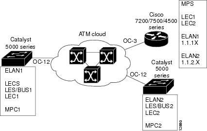
This section contains an example of the commands needed to configure an MPS. The lines beginning with exclamation points (!) are comments explaining the command shown on the following line. Figure 100 shows an example of how you can configure your system to utilize MPOA.
Figure 100 Example of an MPOA Configuration
The following example configures the MPS and attaches the MPS to a hardware interface:
! Define the MPS "MYMPS"mpoa server config name MYMPS! Leave everything as defaultexit! Enter into interface config modeinterface ATM 1/0! Attach MPS MYMPS to the HW interfacempoa server name MYMPS! Go back up to global config modeexitThe following example shows a typical MPS configuration file:
version 11.3hostname MPS! Define the MPS "mps"mpoa server config name mps! Specify the ATM interface to which the MPS is attachedinterface ATM4/0no ip addressatm pvc 1 0 5 qsaalatm pvc 2 0 16 ilmilane config auto-config-atm-addressmpoa server name mps! Specify the ATM interface that contains the LEC to which you will bind the MPSinterface ATM4/0.1 multipointip address 1.1.1.2 255.255.255.0lane client mpoa server name mpslane client ethernet elan1interface ATM4/0.2 multipointip address 1.1.2.1 255.255.255.0lane client mpoa server name mpslane client ethernet elan2end