Feedback
Table Of Contents
Configuring Logical Interfaces
Configuring a Loopback Interface
Troubleshooting Channelized E1 and Channelized T1
Running Controller Loopback Diagnostic Tests
Channelized E1 Controller Loopback
Channelized E1 Controller Example
Channelized T1 Controller Examples
Configuring a Tunnel Interface
Special Considerations for Configuring Tunnel Interfaces
IP Tunneling Configuration Task List
Specifying the Tunnel Interface
Configuring the Tunnel Destination
Configuring End-to-End Checksumming
Configuring a Tunnel Identification Key
Configuring a Tunnel Interface to Drop Out-of-Order Datagrams
Configuring Asynchronous Host Mobility
Configuring IP over a CLNS Tunnel
Verifying IP over CLNS Tunnel Configuration
Monitoring and Maintaining IP over a CLNS Tunnel
Logical Interface Configuration Examples
Configuring GRE/IPv4 Tunnels: Examples
Routing Two AppleTalk Networks across an IP-Only Backbone Example
Routing a Private IP Network and a Novell Network Across a Public Service Provider Example
Configuring IP over a CLNS Tunnel Example
Configuring Logical Interfaces
Use the information in this chapter to understand and configure the types of logical, or virtual, interfaces supported on Cisco routers and access servers. This chapter includes the following sections:
•
Configuring a Loopback Interface
•
•
For examples of configuration tasks, see the "Logical Interface Configuration Examples" section.
For hardware technical descriptions and information about installing interfaces, refer to the hardware installation and configuration publication for your product. For complete descriptions of the logical interface commands, refer to the "Interface Commands" chapter of the Cisco IOS Interface Command Reference. To locate documentation of other commands that appear in this chapter, use the command reference master index or search online.
To identify the hardware platform or software image information associated with a feature, use the Feature Navigator on Cisco.com to search for information about the feature or refer to the software release notes for a specific release. For more information, see the "Identifying Supported Platforms" in "Using Cisco IOS Software."
Configuring a Loopback Interface
You can specify a software-only interface called a loopback interface to emulate an interface. Loopback interfaces are supported on all platforms. A loopback interface is a virtual interface that is always up and allows Border Gateway Protocol (BGP) and remote source-route bridging (RSRB) sessions to stay up even if the outbound interface is down.
You can use the loopback interface as the termination address for BGP sessions, for RSRB connections, or to establish a Telnet session from the device's console to its auxiliary port when all other interfaces are down. You can also use a loopback interface to configure IPX-PPP on asynchronous interfaces. To do so, you must associate an asynchronous interface with a loopback interface configured to run IPX. In applications in which other routers or access servers attempt to reach this loopback interface, you should configure a routing protocol to distribute the subnet assigned to the loopback address.
Packets routed to the loopback interface are rerouted back to the router or access server and processed locally. IP packets routed out the loopback interface but not destined to the loopback interface are dropped. This means that the loopback interface serves as the Null 0 interface also.
Note
To specify a loopback interface and enter interface configuration mode, use one of the following commands in global configuration mode:
For more general information about loopback interfaces, see the "Running Interface Loopback Diagnostics" section in the "Features for Any Interface" chapter.
Troubleshooting Channelized E1 and Channelized T1
When troubleshooting channelized T1 or E1, you must first determine if the problem is with a particular channel group or with the T1 or E1 line.
If the problem is with a single channel group, you have a potential interface problem.
If the problem is with the T1 or E1 line, or with all channel groups, you have a potential controller problem.
The following sections describe how to determine whether the problem affects an interface or a controller:
•
•
When you troubleshoot E1 or T1 controllers, first check that the configuration is correct. The framing type and line code should match what the service provider has specified. Then check channel group and PRI-group configurations, especially to verify that the time slots and speeds are what the service provider has specified.
At this point, the show controllers t1 or show controllers e1 commands should be used to check for T1 or E1 errors. Use the command several times to determine if error counters are increasing, or if the line status is continually changing. If these errors are occurring, you need to work with the service provider.
Note
Running Controller Loopback Diagnostic Tests
Controller loopback tests are a means to isolate problems and are available for both channelized T1 controllers and channelized E1 controllers. The following loopback tests are documented for isolating T1 and E1 controller issues:
•
Local Loopback
The local loopback loops the controller both toward the router and toward the line. Because the loopback is done internally to the router, the controller should make the transition to the UP state within approximately 10 seconds, and no further T1 errors should be detected.
All channel groups will be looped back; if the encapsulation on that channel group supports loopbacks (for example, HDLC and PPP), you can test that channel group by pinging the interface address. For example, if you have assigned an IP address to the serial interface defined for a channel group, you can ping that IP address.
To place the controller into local loopback, use the following command in controller configuration mode:
Router(config-controller)# loopback local controller
Loops the T1 controller toward the router and toward the line.
To test a channel group, use the following command in EXEC mode:
To check errors, use the following command in EXEC mode:
If any errors occur, or the controller fails to change to the up state, contact the Cisco Technical Assistance Center (TAC).
Because the controller local loopback is bidirectional, the service provider can test the line integrity using a T1 bit error rate tester (BERT) test set.
Remote Loopback
The second T1 controller loopback is a remote loopback. This loopback can be used only if the entire T1 goes to a remote CSU. This is not the case with 99.9 percent of channelized T1. When the loopback remote controller command is executed, an in-band CSU loop-up code will be sent over the entire T1, which will attempt to loop up the remote CSU. To place the controller in remote loopback, use the following command in controller configuration mode:
Router(config-controller)# loopback remote controller
Places the T1 controller in remote loopback.
Note
Channelized E1 Controller Loopback
For the E1 controller, only the local loopback is available. Local loopback operates the same as the local loopback on the T1 controller, forming a bidirectional loopback, both toward the router and toward the line. To place the E1 controller in local loopback, use the following command in controller configuration mode:
Router(config-controller)# loopback controller
Places the E1 controller in local loopback toward the router and toward the line.
All channel groups will be looped back; if the encapsulation on that channel group supports loopbacks (for example, HDLC and PPP), you can test that channel group by pinging the interface address. For example, if you have assigned an IP address to the serial interface defined for a channel group, you can ping that IP address.
To place the controller into local loopback, use the following command in controller configuration mode:
Router(config-controller)# loopback local controller
Loops the T1 controller toward the router and toward the line.
To test a channel group, use the following command in EXEC mode:
To check errors, if any, use the following command in EXEC mode:
If any errors occur, they are most likely a hardware problem; contact the Cisco TAC. In addition, you can ask the service provider to test the line by using a T1 BERT test set.
Channelized E1 Controller Example
The following example configures a Cisco 7500 series router to acknowledge an E1 line:
controller e1 3/0channel-group 0 timeslots 1channel-group 8 timeslots 5-15, 20-30channel-group 12 timeslots 2channel-group 29 timeslots 31Channelized T1 Controller Examples
The following example applies only to a Cisco 7500 series router. It configures the router to acknowledge a T1 line and its circuits. Four different circuits (and their corresponding serial interfaces) are defined for the second CxCT1 attached to the MIP in slot 4.
controller t1 4/1framing esflinecode b8zschannel-group 0 timeslots 1channel-group 8 timeslots 5,7,12-15, 20 speed 64channel-group 12 timeslots 2channel-group 23 timeslots 24The following example configures circuit 0 for PPP encapsulation:
interface serial 4/1:0ip address 172.18.13.1 255.255.255.0encapsulation pppThe following example configures circuit 8 for IP routing and disables IP route cache:
interface serial 4/1:8ip address 172.18.1.1 255.255.255.0no ip route-cacheThe following example configures circuit 12 for Frame Relay encapsulation and subinterface support:
interface serial 4/1:12encapsulation frame-relay!interface serial 4/1:12.1ip address 10.1.1.1 255.0.0.0!interface serial 4/1:12.2ip address 10.2.2.2 255.0.0.0The following example configures circuit 23 for IP routing and enables autonomous switching:
interface serial 4/1:23ip address 10.3.3.3 255.0.0.0ip route-cache cbusConfiguring a Null Interface
The Cisco IOS software supports a "null" interface. This pseudo-interface functions similarly to the null devices available on most operating systems. This interface is always up and can never forward or receive traffic; encapsulation always fails. The only interface configuration command that you can specify for the null interface is no ip unreachables.
The null interface provides an alternative method of filtering traffic. You can avoid the overhead involved with using access lists by directing undesired network traffic to the null interface.
To specify the null interface, use the following command in global configuration mode:
Specify null 0 (or null0) as the interface type and number. The null interface can be used in any command that has an interface type as an argument. The following example configures a null interface for IP route 127.0.0.0:
ip route 127.0.0.0 255.0.0.0 null 0Configuring a Tunnel Interface
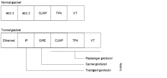
Tunneling provides a way to encapsulate arbitrary packets inside a transport protocol. This feature is implemented as a virtual interface to provide a simple interface for configuration. The tunnel interface is not tied to specific "passenger" or "transport" protocols, but rather, it is an architecture that is designed to provide the services necessary to implement any standard point-to-point encapsulation scheme. Because tunnels are point-to-point links, you must configure a separate tunnel for each link.
Tunneling has the following three primary components:
•
•
–
–
–
–
–
•
Figure 22 illustrates IP tunneling terminology and concepts.
Figure 22 IP Tunneling Terminology and Concepts
To understand the process of tunneling, consider connecting two AppleTalk networks with a non-AppleTalk backbone, such as IP. The relatively high bandwidth consumed by the broadcasting of Routing Table Maintenance Protocol (RTMP) data packets can severely hamper the backbone's network performance. This problem can be solved by tunneling AppleTalk through a foreign protocol, such as IP. Tunneling encapsulates an AppleTalk packet inside the foreign protocol packet, which is then sent across the backbone to a destination router. The destination router then removes the encapsulation from the AppleTalk packet and, if necessary, routes the packet to a normal AppleTalk network. Because the encapsulated AppleTalk packet is sent in a directed manner to a remote IP address, bandwidth usage is greatly reduced. Furthermore, the encapsulated packet benefits from any features normally enjoyed by IP packets, including default routes and load balancing.
Advantages of Tunneling
The following are several situations in which encapsulating traffic in another protocol is useful:
•
•
•
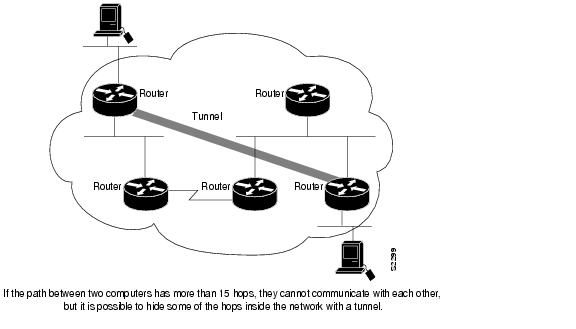
•
Figure 23 Providing Workarounds for Networks with Limited Hop Counts
Special Considerations for Configuring Tunnel Interfaces
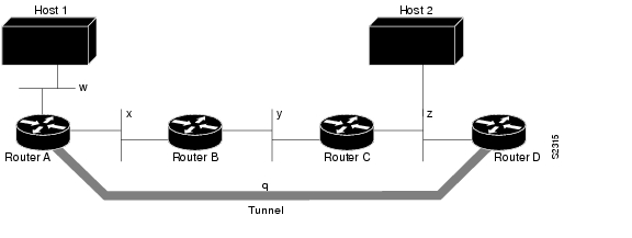
The following are considerations and precautions to observe when you configure tunneling:
•
•
•
•
•
•
•
–
–
–
•
%TUN-RECURDOWN Interface Tunnel 0temporarily disabled due to recursive routingFigure 24 Tunnel Precautions: Hop Counts
IP Tunneling Configuration Task List
To configure IP tunneling, perform the following tasks. Each task in the list is identified as either required or optional.
•
•
•
•
•
•
•
•
For commands that monitor IP tunnels, see the "Monitoring and Maintaining the Interface" section in the "Features for Any Interface" chapter. For examples of configuring tunnels, see the "IP Tunneling: Example" section.
Specifying the Tunnel Interface
To specify a tunnel interface and enter interface configuration mode, use one of the following commands in global configuration mode:
Configuring the Tunnel Source
To specify the source address for the tunnel interface, use the following command in interface configuration mode:
Router(config-if)# tunnel source {ip-address | type number}
Configures the tunnel source.
Note
Configuring the Tunnel Destination
To specify the destination for the tunnel interface, use the following command in interface configuration mode:
Router(config-if)# tunnel destination {hostname | ip-address}
Configures the tunnel destination.
Configuring the Tunnel Mode
The encapsulation mode for the tunnel interface defaults to generic route encapsulation (GRE), so this command is considered optional. However, if you want a mode other than GRE, you must configure it by using the following command in interface configuration mode:
Router(config-if)# tunnel mode {aurp | cayman | dvmrp | eon | gre ip | nos}
Configures the tunnel mode.
If you are tunneling AppleTalk, you must use the AppleTalk Update Routing Protocol (AURP), Cayman, or GRE tunneling mode. Cayman tunneling is designed by Cayman Systems and enables routers and access servers to interoperate with Cayman GatorBoxes. You can have Cisco devices at either end of the tunnel, or you can have a GatorBox at one end and a Cisco router or access server at the other end. Use Distance Vector Multicast Routing Protocol (DVMRP) mode when a router or access server connects to a mrouted router to run DVMRP over a tunnel. You must configure Protocol-Independent Multicast (PIM) and an IP address on a DVMRP tunnel.
Caution
Note
If you use GRE, you must have only Cisco routers or access servers at both ends of the tunnel connection. When you use GRE to tunnel AppleTalk, you must configure an AppleTalk network address and a zone. To tunnel AppleTalk using GRE, use the following commands beginning in global configuration mode:
Configuring End-to-End Checksumming
Some passenger protocols rely on media checksums to provide data integrity. By default, the tunnel does not guarantee packet integrity. By enabling end-to-end checksums, the Cisco IOS software drops corrupted packets. To enable such checksums on a tunnel interface, use the following command in interface configuration mode:
Configuring a Tunnel Identification Key
You can enable an ID key for a tunnel interface. This key must be set to the same value on the tunnel endpoints. Tunnel ID keys can be used as a form of weak security to prevent incorrect configuration or injection of packets from a foreign source.
Note
The tunnel ID key is available with GRE only.
Note
To configure a tunnel ID key, use the following command in interface configuration mode:
Configuring a Tunnel Interface to Drop Out-of-Order Datagrams
You can optionally configure a tunnel interface to drop datagrams that arrive out of order. This is useful when carrying passenger protocols that function poorly when they receive packets out of order (for example, LLC2-based protocols). This option is available with GRE only. To use this option, use the following command in interface configuration mode:
Router(config-if)# tunnel sequence-datagrams
Configures a tunnel interface to drop out-of-order datagrams.
Configuring Asynchronous Host Mobility
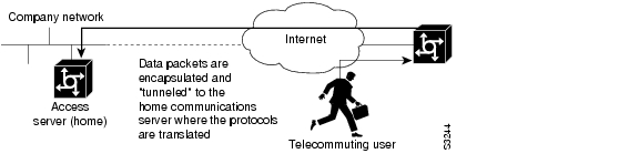
Increasingly, remote users are accessing networks through dial-up telephone connections. In contrast to local users who can connect directly into the network, remote users must first dial in to an access server.
The access server supports a packet tunneling strategy that extends the internetwork—in effect creating a virtual private link for the mobile user. When a user activates asynchronous host mobility, the access server on which the remote user dials into becomes a remote point-of-presence (POP) for the home network of the user. Once logged in, users experience a server environment identical to the one that they experience when they connect directly to the "home" access server.
Once the network layer connection is made, data packets are tunneled at the physical and/or data link layer instead of at the protocol layer. In this way, raw data bytes from dial-in users are transported directly to the "home" access server, which processes the protocols.
Figure 25 illustrates the implementation of asynchronous host mobility on an extended internetwork. A mobile user connects to an access server on the internetwork and, by activating asynchronous host mobility, is connected to a "home" access server configured with the appropriate username. The user sees an authentication dialog or prompt from the "home" system and can proceed as if connected directly to that device.
Figure 25 Asynchronous Host Mobility
The remote user implements asynchronous host mobility by executing the tunnel command in user EXEC mode. The tunnel command sets up a network layer connection to the specified destination. The access server accepts the connection, attaches it to a virtual terminal (VTY), and runs a command parser capable of running the normal dial-in services. After the connection is established, data is transferred between the modem and network connection with a minimum of interpretations. When communications are complete, the network connection can be closed and terminated from either end.
Refer to the Cisco Access Connection Guide for information about setting up the network layer connection with the tunnel command.
Configuring IP over a CLNS Tunnel
IP over a CLNS tunnel is a virtual interface that enhances interactions with CLNS (Connectionless Network Service) networks, allowing IP packets to be tunneled through the Connectionless Network Protocol (CLNP) to preserve TCP/IP services.
Configuring an IP over CLNS tunnel (CTunnel) allows you to Telnet to a remote router that has only CLNS connectivity. Other management facilities can also be used, such as Simple Network Management Protocol (SNMP) and TFTP, which otherwise would not be available over a CLNS network.
IP over a CLNS Tunnel is supported on all platforms that support ISO CLNS.
To configure IP over a CLNS Tunnel (CTunnel), use the following commands beginning in global configuration mode:
Step 1
Router(config)# interface ctunnel interface-number
Creates a virtual interface to transport IP over a CLNS tunnel and enters interface configuration mode. The interface number must be unique for each CTunnel interface.
Step 2
Router(config-if)# ctunnel destination remote-nsap-address
Configures the destination parameter for the CTunnel. Specifies the destination NSAP1 address of the CTunnel, where the IP packets are extracted.
Step 3
Router(config-if)# ip address ip-address mask
Sets a primary or secondary IP address for an interface.
1 NSAP = network service access point
Note
Verifying IP over CLNS Tunnel Configuration
To verify correct configuration of the IP over a CLNS Tunnel feature, perform the following steps:
Step 1
Step 2
Monitoring and Maintaining IP over a CLNS Tunnel
To display the status of IP over CLNS tunnels, use the following command in privileged EXEC mode:
Router# show interfaces ctunnel interface-number
Displays information about an IP over CLNS tunnel.
Logical Interface Configuration Examples
This section includes the following examples to illustrate configuration tasks described in this chapter:
•
IP Tunneling: Example
The following example shows an IP tunneling configuration with commented (!) explanations:
! Creates the interface.interface tunnel 0! Enables IPX on the interface.novell network 1e! Enables AppleTalk.appletalk cable-range 4001-4001 128! Enables IP.ip address 10.1.2.3. 255.255.255.0! Enables DECnet.DECnet cost 4! Sets the source address, or interface, for packets.tunnel source ethernet 0! Determines where the encapsulated packets are to go.tunnel destination 131.108.14.12! Sets the protocol.tunnel mode gre! Computes a checksum on passenger packets if protocol does not already have reliable ! checksumtunnel checksum needed! Sets the ID key.tunnel key 42! Sets dropping of out-of-order packets.tunnel sequence-datagramsConfiguring GRE/IPv4 Tunnels: Examples
The following example shows a simple configuration of GRE tunneling. Note that Ethernet interface 0/1 is the tunnel source for Router A and the tunnel destination for Router B. Fast Ethernet interface 0/1 is the tunnel source for Router B and the tunnel destination for Router A.
Router A
interface Tunnel0ip address 10.1.1.2 255.255.255.0tunnel source Ethernet0/1tunnel destination 192.168.3.2tunnel mode gre ip!interface Ethernet0/1ip address 192.168.4.2 255.255.255.0Router B
interface Tunnel0ip address 10.1.1.1 255.255.255.0tunnel source FastEthernet0/1tunnel destination 192.168.4.2tunnel mode gre ip!interface FastEthernet0/1ip address 192.168.3.2 255.255.255.0The following example configures a GRE tunnel running both IS-IS and IPv6 traffic between Router A and Router B.
Router A
ipv6 unicast-routingclns routing!interface Tunnel0no ip addressipv6 address 2001:0DB8:1111:2222::1/64ipv6 router isistunnel source Ethernet0/0tunnel destination 10.0.0.2tunnel mode gre ip!interface Ethernet0/0ip address 10.0.0.1 255.255.255.0!router isisnetwork 49.0000.0000.000a.00Router B
ipv6 unicast-routingclns routing!interface Tunnel0no ip addressipv6 address 2001:0DB8:1111:2222::2/64ipv6 router isistunnel source Ethernet0/0tunnel destination 10.0.0.1tunnel mode gre ip!interface Ethernet0/0ip address 10.0.0.2 255.255.255.0!router isisnetwork 49.0000.0000.000b.00address-family ipv6redistribute staticexit-address-familyRouting Two AppleTalk Networks across an IP-Only Backbone Example
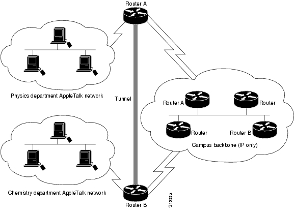
Figure 26 is an example of connecting multiprotocol subnetworks across a single-protocol backbone. The configurations of Router A and Router B follow Figure 26.
Figure 26 Connecting AppleTalk Networks Across an IP-Only Backbone
Router A
interface ethernet 0description physics department AppleTalk LANappletalk cable-range 4001-4001 32!interface fddi 0description connection to campus backboneip address 131.0.8.108 255.255.255.0interface tunnel 0tunnel source fddi 0tunnel destination 131.0.21.20appletalk cable-range 5313-5313 1Router B
interface ethernet 0description chemistry department AppleTalk LANappletalk cable-range 9458-9458 3!interface fddi 0description connection to campus backboneip address 131.0.21.20 255.255.255.0interface tunnel 0tunnel source fddi 0tunnel destination 131.0.8.108appletalk cable-range 5313-5313 2Routing a Private IP Network and a Novell Network Across a Public Service Provider Example
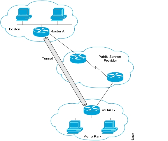
Figure 27 is an example of routing a private IP network and a Novell network across a public service provider. The configuration of Router A and Router B follow Figure 27.
Figure 27 Creating Virtual Private Networks Across WANs
Router A
interface ethernet 0description Boston officeip address 10.1.1.1 255.255.255.0novell network 1e!interface serial 0description connection to NEARnetip address 131.13.2.1 255.255.255.0!interface tunnel 0tunnel source serial 0tunnel destination 131.108.5.2ip address 10.1.2.1 255.255.255.0novell network 1fRouter B
interface ethernet 0description Menlo Park officeip address 10.1.3.1 255.255.255.0novell network 31!interface serial 4description connection to BARRnetip address 131.108.5.2 255.255.255.0!interface tunnel 0tunnel source serial 4tunnel destination 131.13.2.1ip address 10.1.2.2 255.255.255.0novell network 1fConfiguring IP over a CLNS Tunnel Example
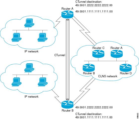
Figure 28 illustrates the creation of a CTunnel between Router A and Router B, as accomplished in the configuration examples that follow for Router A and Router B:
Figure 28 Creation of a CTunnel
Router A
ip routingclns routinginterface ctunnel 102ip address 10.0.0.1 255.255.255.0ctunnel destination 49.0001.2222.2222.2222.00interface Ethernet0/1clns router isisrouter isisnet 49.0001.1111.1111.1111.00router ripnetwork 10.0.0.0Router B
ip routingclns routinginterface ctunnel 201ip address 10.0.0.2 255.255.255.0ctunnel destination 49.0001.1111.1111.1111.00interface Ethernet0/1clns router isisrouter isisnet 49.0001.2222.2222.2222.00router ripnetwork 10.0.0.0