Feedback
Table Of Contents
Dial Shelf Management Task List
Understanding Shelf Architecture and DSIP
Maintaining Dial Shelf Controllers
Monitoring and Maintaining DSCs and Feature Boards
Managing Dial Shelves
This chapter discusses configuration and monitoring tasks for dial shelves and dial shelf controllers, particularly on Cisco AS5800 Universal Access Servers.
To identify the hardware platform or software image information associated with a feature, use the Feature Navigator on Cisco.com to search for information about the feature or refer to the software release notes for a specific release. For more information, see the Identifying Supported Platforms in "Using Cisco IOS Software."
For additional information about the technologies in this chapter, see the following publications:
•
Dial and System Management Commands for the Cisco AS5800
(This document is available online only.)•
•
For hardware technical descriptions and information about installing interfaces, refer to the hardware installation and configuration publication for your product. For a complete description of dial shelf management commands in this chapter, refer to the "Dial Shelf Management Commands" chapter in the Release 12.2 Cisco IOS Interface Command Reference. To locate documentation of other commands that appear in this chapter, use the command reference master index or search online.
Dial Shelf Management Task List
Perform the tasks found in the following sections to manage dial shelves:
•
•
Understanding Shelf Architecture and DSIP
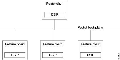
The Cisco AS5800 is a rack-mounted system consisting of a router shelf and a dial shelf. The dial shelf contains trunk cards, modem cards, and dial shelf controller (DSC) cards. The trunk cards and modem cards are referred to collectively as feature boards. Slots 0 through 11 of the dial shelf are reserved for feature boards, while slots 12 and 13 are reserved for the DSC cards. The AS5800 series supports the use of a single router shelf or two router shelves (split-shelf configuration), and the use of a single DSC or two DSCs (DSC redundancy) for backup purposes.
Dial Shelf Interconnect Protocol (DSIP) is used for communication between router shelf and dial shelf on an AS5800. Figure 29 diagrams the components of the architecture. DSIP communicates over the packet backplane via the dial shelf interconnect (DSI) cable.
Figure 29 DSIP Architecture in the Cisco AS5800
Maintaining Shelves
Perform the tasks described in the following sections to perform the respective configuration tasks:
Configuring the Shelf IDs
The Cisco AS5800 consists of one or more router shelves and a dial shelf. Shelf ID numbers and port numbers are used to identify specific components in your system. The default shelf number is 0 for the router shelf and 1 for the dial shelf.
Normally you do not need to change the shelf IDs; however, if you do, we recommend that you change the shelf number when you initially access the setup facility. For information on the setup facility, refer to the Cisco AS5800 Universal Access Server Software Installation and Configuration Guide.
Caution
If you are booting the router shelf from the network (netbooting), you can change the shelf numbers using the shelf-id command. Perform the following tasks beginning in EXEC mode:
If you are booting the router shelf from Flash memory, perform the following tasks beginning in EXEC mode:
Executing Commands Remotely
It is possible to connect directly to the system console interface on the DSC to execute dial shelf configuration commands, but this is not recommended. All commands necessary for dial shelf configuration, including show and debug tasks, can be executed remotely through the router console. A special command called execute-on is provided for this purpose. This command enables a special set of Exec mode commands to be executed on the router or the dial shelf. This command is a convenience that avoids connecting the console to the DSC. For a list of commands you can execute using execute-on, see the complete command description in the Release 12.1 Cisco IOS Configuration Fundamentals Command Reference.
To enter a command that you wish to execute on a specific card installed in the dial shelf while logged onto the router shelf console, use the following privileged EXEC mode commands:
Maintaining Dial Shelf Controllers
The DSC card provides the following:
•
•
•
•
The Cisco AS5800 dial shelf can contain two DSC cards. With two DSC cards present, DSC redundancy automatically provides for one DSC to act as a backup to the active one. This redundancy feature is implemented to increase system availability by preventing loss of service in the event of the failure of one of the DSCs. The redundancy is intended to be transparent to most Cisco AS5800 software (redundancy is supported at or below the DSIP layer). Software modules using the DSIP services are generally not aware of nor need to take part in the management of dual DSCs.
Configuring Clocks
The TDM bus in the backplane on the dial shelf must be synchronized to the T1/E1 clocks on the trunk cards. The Dial Shelf Controller (DSC) card on the dial shelf provides hardware logic to accept multiple clock sources as input and use one of them as the primary source to generate a stable, PPL synchronized output clock. The input clock can be any of the following sources:
•
•
•
For dual (redundant) DSC cards, the external DSC clocking port should be configured so that the clock signal fed into both DSCs is identical.
To configure the clock source and priority of the clock source used by the TDM bus, perform one or more of the following tasks, beginning in global configuration mode:
Monitoring and Maintaining DSCs and Feature Boards
Use the following commands in privileged EXEC mode to swap dial shelf cards or to troubleshoot the dial shelf cards from the router shelf:
Troubleshooting Using DSIP
There are a number of show commands available to aid in troubleshooting Dial Shelves. Use any of the following EXEC mode commands to monitor DSI and DSIP activity:
The privileged EXEC mode show dsi command can also be used to troubleshoot, as it displays the status of the DSI adapter, which is used to physically connect the router shelf and the dial shelf to enable DSIP communications.
The following is an example troubleshooting scenario:
Problem: The router shelf boots, but there is no communication between the router and dial shelves.
Step 1
Step 2
Step 3
Step 4
Diagnosis: If an entry for a particular dial shelf slot is not found among the registered addresses, but most of other card entries are present, the problem is most likely with that dial shelf slot. The DSI hardware on that feature board is probably bad.