-
Cisco IOS Dial Technologies Configuration Guide, Release 12.2
-
About Cisco IOS Software Documentation
-
Using Cisco IOS Software
- Part 1: Dial Interfaces, Controllers, and Lines
- Part 2: Modem Configuration Management
- Part 3: ISDN Configuration
- Part 4: Signaling Configuration
- Part 5: Dial-on-Demand Routing Configuration
- Part 6: Dial-Backup Configuration
- Part 7: Dial-Related Addressing Services
- Part 8: Virtual Templates, Profiles, and Networks
- Part 9: PPP Configuration
- Part 10: Callback and Bandwidth Allocation Configuration
- Part 11: Dial Access Specialized Features
- Part 12: Dial Access Scenarios
- Part 13: Appendix
-
 Feedback
Table Of Contents
Configuring Media-Independent PPP and Multilink PPP
Enabling CHAP or PAP Authentication
Enabling Link Quality Monitoring
Configuring Compression of PPP Data
Hardware-Dependent Compression
Configuring Microsoft Point-to-Point Compression
Configuring IP Address Pooling
Choosing the IP Address Assignment Method
Defining the Global Default Address Pooling Mechanism
Controlling DHCP Network Discovery
Configuring IP Address Assignment
Disabling or Reenabling Peer Neighbor Routes
Configuring MLP on Synchronous Interfaces
Configuring MLP on Asynchronous Interfaces
Configuring MLP on a Single ISDN BRI Interface
Configuring MLP on Multiple ISDN BRI Interfaces
Configuring MLP Using Multilink Group Interfaces
Changing the Default Endpoint Discriminator
Configuring MLP Interleaving and Queueing
Configuring MLP Inverse Multiplexer and Distributed MLP
Enabling Distributed CEF Switching
Assigning an Interface to a Multilink Bundle
Disabling PPP Multilink Fragmentation
Verifying the MLP Inverse Multiplexer Configuration
Monitoring and Maintaining PPP and MLP Interfaces
Configuration Examples for PPP and MLP
CHAP with an Encrypted Password Examples
User Maximum Links Configuration Example
MPPC Interface Configuration Examples
MLP on Synchronous Serial Interfaces Example
MLP on One ISDN BRI Interface Example
MLP on Multiple ISDN BRI Interfaces Example
MLP Using Multilink Group Interfaces over ATM Example
Changing the Default Endpoint Discriminator Example
MLP Interleaving and Queueing for Real-Time Traffic Example
T3 Controller Configuration for an MLP Multilink Inverse Multiplexer Example
Multilink Interface Configuration for Distributed MLP Example
Configuring Media-Independent PPP and Multilink PPP
This chapter describes how to configure the PPP and Multilink PPP (MLP) features that can be configured on any interface. It includes the following main sections:
•
Configuring MLP Interleaving and Queueing
•
•
•
This chapter also describes address pooling for point-to-point links, which is available on all asynchronous serial, synchronous serial, and ISDN interfaces. See the chapter "Configuring Asynchronous SLIP and PPP" in this publication for information about PPP features and requirements that apply only to asynchronous lines and interfaces.
To identify the hardware platform or software image information associated with a feature, use the Feature Navigator on Cisco.com to search for information about the feature or refer to the software release notes for a specific release. For more information, see the "Identifying Supported Platforms" section in the "Using Cisco IOS Software" chapter.
For a complete description of the PPP commands in this chapter, refer to the Cisco IOS Dial Technologies Command Reference. To locate documentation of other commands that appear in this chapter, use the command reference master index or search online.
PPP Encapsulation Overview
PPP, described in RFC 1661, encapsulates network layer protocol information over point-to-point links. You can configure PPP on the following types of physical interfaces:
•
•
•
•
Challenge Handshake Authentication Protocol (CHAP) or Password Authentication Protocol (PAP)Magic Number support is available on all serial interfaces. PPP always attempts to negotiate for Magic Numbers, which are used to detect looped-back lines. Depending on how the down-when-looped command is configured, the router might shut down a link if it detects a loop.
The software provides the CHAP and PAP on serial interfaces running PPP encapsulation. For detailed information about authentication, refer to the Cisco IOS Security Configuration Guide.
Beginning with Cisco IOS Release 11.2 F, Cisco supported fast switching of incoming and outgoing DECnet and CLNS packets over PPP.
Configuring PPP and MLP
To configure PPP on a serial interface (including ISDN), perform the following task in interface configuration mode. This task is required for PPP encapsulation.
You can also complete the tasks in the following sections; these tasks are optional but offer a variety of uses and enhancements for PPP on your systems and networks:
•
•
•
•
•
•
•
•
•
•
•
•
See the section "Monitoring and Maintaining PPP and MLP Interfaces" later in this chapter for tips on maintaining PPP. See the "Configuration Examples for PPP and MLP" at the end of this chapter for ideas on how to implement PPP and MLP in your network.
Enabling PPP Encapsulation
To enable PPP on serial lines to encapsulate IP and other network protocol datagrams, use the following command in interface configuration mode:
Enabling CHAP or PAP Authentication
PPP with CHAP or PAP authentication is often used to inform the central site about which remote routers are connected to it.
With this authentication information, if the router or access server receives another packet for a destination to which it is already connected, it does not place an additional call. However, if the router or access server is using rotaries, it sends the packet out the correct port.
CHAP and PAP were originally specified in RFC 1334, and CHAP is updated in RFC 1994. These protocols are supported on synchronous and asynchronous serial interfaces. When using CHAP or PAP authentication, each router or access server identifies itself by a name. This identification process prevents a router from placing another call to a router to which it is already connected, and also prevents unauthorized access.
Access control using CHAP or PAP is available on all serial interfaces that use PPP encapsulation. The authentication feature reduces the risk of security violations on your router or access server. You can configure either CHAP or PAP for the interface.
Note
When CHAP is enabled on an interface and a remote device attempts to connect to it, the local router or access server sends a CHAP packet to the remote device. The CHAP packet requests or "challenges" the remote device to respond. The challenge packet consists of an ID, a random number, and the host name of the local router.
The required response has two parts:
•
•
When the local router or access server receives the response, it verifies the secret password by performing the same encryption operation as indicated in the response and looking up the required host name or username. The secret passwords must be identical on the remote device and the local router.
Because this response is sent, the password is never sent in clear text, preventing other devices from stealing it and gaining illegal access to the system. Without the proper response, the remote device cannot connect to the local router.
CHAP transactions occur only when a link is established. The local router or access server does not request a password during the rest of the call. (The local device can, however, respond to such requests from other devices during a call.)
When PAP is enabled, the remote router attempting to connect to the local router or access server is required to send an authentication request. If the username and password specified in the authentication request are accepted, the Cisco IOS software sends an authentication acknowledgment.
After you have enabled CHAP or PAP, the local router or access server requires authentication from remote devices. If the remote device does not support the enabled protocol, no traffic will be passed to that device.
To use CHAP or PAP, you must perform the following tasks:
•
•
•
To enable PPP encapsulation, use the following command in interface configuration mode:
To enable CHAP or PAP authentication on an interface configured for PPP encapsulation, use the following command in interface configuration mode:
The ppp authentication chap optional keyword if-needed can be used only with Terminal Access Controller Access Control System (TACACS) or extended TACACS.
With authentication, authorization, and accounting (AAA) configured on the router and list names defined for AAA, the list-name optional keyword can be used with AAA/TACACS+.
Caution
Add a username entry for each remote system from which the local router or access server requires authentication.
To specify the password to be used in CHAP or PAP caller identification, use the following command in global configuration mode:
Make sure this password does not include spaces or underscores.
To configure TACACS on a specific interface as an alternative to global host authentication, use one of the following commands in interface configuration mode:
Router(config-if)# ppp use-tacacs [single-line]
or
Router(config-if)# aaa authentication ppp
Configures TACACS.
Use the ppp use-tacacs command with TACACS and Extended TACACS. Use the aaa authentication ppp command with AAA/TACACS+.
For an example of CHAP, see the section "CHAP with an Encrypted Password Examples" at the end of this chapter. CHAP is specified in RFC 1994, PPP Challenge Handshake Authentication Protocol (CHAP).
Enabling Link Quality Monitoring
Link Quality Monitoring (LQM) is available on all serial interfaces running PPP. LQM will monitor the link quality, and if the quality drops below a configured percentage, the router will shut down the link. The percentages are calculated for both the incoming and outgoing directions. The outgoing quality is calculated by comparing the total number of packets and bytes sent with the total number of packets and bytes received by the destination node. The incoming quality is calculated by comparing the total number of packets and bytes received with the total number of packets and bytes sent by the destination peer.
Note
When LQM is enabled, Link Quality Reports (LQRs) are sent, in place of keepalives, every keepalive period. All incoming keepalives are responded to properly. If LQM is not configured, keepalives are sent every keepalive period and all incoming LQRs are responded to with an LQR.
LQR is specified in RFC 1989, PPP Link Quality Monitoring.
To enable LQM on the interface, use the following command in interface configuration mode:
The percentage argument specifies the link quality threshold. That percentage must be maintained, or the link is deemed to be of poor quality and is taken down.
Configuring Compression of PPP Data
You can configure point-to-point software compression on serial interfaces that use PPP encapsulation. Compression reduces the size of a PPP frame via lossless data compression. PPP encapsulations support both predictor and Stacker compression algorithms.
If most of your traffic is already compressed files, do not use compression.
Most routers support software compression only, but in the Cisco 7000 series routers, hardware compression and distributed compression are also available, depending on the interface processor and compression service adapter hardware installed in the router.
To configure compression, complete the tasks in one of the following sections:
•
Software Compression
Software compression is available in all router platforms. Software compression is performed by the main processor in the router.
Compression is performed in software and might significantly affect system performance. We recommend that you disable compression if the router CPU load exceeds 65 percent. To display the CPU load, use the show process cpu EXEC command.
To configure compression over PPP, use the following commands in interface configuration mode:
Hardware-Dependent Compression
When you configure Stacker compression on Cisco 7000 series routers with a 7000 Series Route Switch Processor (RSP7000), on Cisco 7200 series routers, and on Cisco 7500 series routers, there are three methods of compression: hardware compression, distributed compression, and software compression.
Hardware and distributed compression are available on routers that have the SA-Comp/1 and SA-Comp/4 data compression service adapters (CSAs). CSAs are available on Cisco 7200 series routers, on Cisco 7500 series routers with second-generation Versatile Interface Processors (VIP2s), and on Cisco 7000 series routers with the RSP7000 and 7000 Series Chassis Interface (RSP7000CI). (CSAs require VIP2 model VIP2-40.)
To configure hardware or distributed compression over PPP, use the following commands in interface configuration mode:
Specifying the compress stac command with no options causes the router to use the fastest available compression method:
•
•
•
Using hardware compression in the CSA frees the main processor of the router for other tasks. You can also configure the router to use the VIP2 to perform compression by using the distributed option, or to use the main processor of the router by using the software option. If the VIP2 is not available, compression is performed in the main processor of the router.
When compression is performed in software installed in the main processor of the router, it might substantially affect system performance. We recommend that you disable compression in the main processor of the router if the router CPU load exceeds 40 percent. To display the CPU load, use the show process cpu EXEC command.
Specifying the compress stac command with no options causes the router to use the fastest available compression method.
Configuring Microsoft Point-to-Point Compression
Microsoft Point-to-Point Compression (MPPC) is a scheme used to compress PPP packets between Cisco and Microsoft client devices. The MPPC algorithm is designed to optimize bandwidth utilization in order to support multiple simultaneous connections. The MPPC algorithm uses a Lempel-Ziv (LZ)-based algorithm with a continuous history buffer called a dictionary.
The Compression Control Protocol (CCP) configuration option for MPPC is 18.
Exactly one MPPC datagram is encapsulated in the PPP information field. The PPP protocol field indicates the hexadecimal type of 00FD for all compressed datagrams. The maximum length of the MPPC datagram sent over PPP is the same as the MTU of the PPP interface; however, this length cannot be greater than 8192 bytes because the history buffer is limited to 8192 bytes. If compressing the data results in data expansion, the original data is sent as an uncompressed MPPC packet.
The history buffers between compressor and decompressor are synchronized by maintaining a 12-bit coherency count. If the decompressor detects that the coherency count is out of sequence, the following error recovery process is performed:
1.
2.
3.
Synchronization is achieved without CCP using the Reset Acknowledge (RA) packet, which can consume additional time.
Compression negotiation between a router and a Windows 95 client occurs through the following process:
1.
2.
3.
4.
MPPC Restrictions
The following restrictions apply to the MPPC feature:
•
•
•
Configuring MPPC
PPP encapsulation must be enabled before you can configure MPPC. For information on how to configure PPP encapsulation, see the section "Enabling PPP Encapsulation" earlier in this chapter.
There is only one command required to configure MPPC. The existing compress command supports the mppc keyword, which prepares the interface to initiate CCP and negotiates MPPC with the Microsoft client. To set MPPC once PPP encapsulation is configured on the router, use the following command in interface configuration mode:
The ignore-pfc keyword instructs the router to ignore the protocol field compression flag negotiated by LCP. For example, the uncompressed standard protocol field value for IP is 0x0021 and 0x21 when compression is enabled. When the ignore-pfc option is enabled, the router will continue to use the uncompressed value (0x0021). Using the ignore-pfc option is helpful for some asynchronous driver devices that use an uncompressed protocol field (0x0021), even though the protocol field compression is negotiated between peers. displays protocol rejections when the debug ppp negotiation command is enabled. These errors can be remedied by setting the ignore-pfc option.
Sample debug ppp negotiation Command Output Showing Protocol Reject
PPP Async2: protocol reject received for protocol = 0x2145PPP Async2: protocol reject received for protocol = 0x2145PPP Async2: protocol reject received for protocol = 0x2145Configuring IP Address Pooling
A point-to-point interface must be able to provide a remote node with its IP address through the IP Control Protocol (IPCP) address negotiation process. The IP address can be obtained from a variety of sources. The address can be configured through the command line, entered with an EXEC-level command, provided by TACACS+ or the Dynamic Host Configuration Protocol (DHCP), or from a locally administered pool.
IP address pooling uses a pool of IP addresses from which an incoming interface can provide an IP address to a remote node through IPCP address negotiation process. IP address pooling also enhances configuration flexibility by allowing multiple types of pooling to be active simultaneously.
See the chapter "Configuring Asynchronous SLIP and PPP" in this publication for additional information about address pooling on asynchronous interfaces and about the Serial Line Internet Protocol (SLIP).
Peer Address Allocation
A peer IP address can be allocated to an interface through several methods:
•
•
•
•
•
•
•
•
•
•
Precedence Rules
The following precedence rules of peer IP address support determine which address is used. Precedence is listed from most likely to least likely:
1.
2.
3.
4.
5.
6.
Interfaces Affected
Address pooling is available on all asynchronous serial, synchronous serial, ISDN BRI, and ISDN PRI interfaces that are running PPP.
Choosing the IP Address Assignment Method
The IP address pooling feature now allows configuration of a global default address pooling mechanism, per-interface configuration of the address pooling mechanism, and per-interface configuration of a specific address or pool name.
You can define the type of IP address pooling mechanism used on router interfaces in one or both of the ways described in the following sections:
•
•
Defining the Global Default Address Pooling Mechanism
The global default mechanism applies to all point-to-point interfaces that support PPP encapsulation and that have not otherwise been configured for IP address pooling. You can define the global default mechanism to be either DHCP or local address pooling.
To configure the global default mechanism for IP address pooling, perform the tasks in one of following sections:
•
•
After you have defined a global default mechanism, you can disable it on a specific interface by configuring the interface for some other pooling mechanism. You can define a local pool other than the default pool for the interface or you can configure the interface with a specific IP address to be used for dial-in peers.
You can also control the DHCP network discovery mechanism; see the following section for more information:
•
Defining DHCP as the Global Default Mechanism
DHCP specifies the following components:
•
•
To enable DHCP as the global default mechanism, use the following commands in global configuration mode:
In Step 2, you can provide as few as one or as many as ten DHCP servers for the proxy-client (the Cisco router or access server) to use. DHCP servers provide temporary IP addresses.
Defining Local Address Pooling as the Global Default Mechanism
To specify that the global default mechanism to use is local pooling, use the following commands in global configuration mode:
If no other pool is defined, a local pool called "default" is used. Optionally, you can associate an address pool with a named pool group.
Controlling DHCP Network Discovery
To allow peer routers to dynamically discover Domain Name System (DNS) and NetBIOS name server information configured on a DHCP server using PPP IP Control Protocol (IPCP) extensions, use the following command in global configuration mode:
The ip dhcp-client network-discovery global configuration command provides a way to control the DHCP network discovery mechanism. The number of DHCP Inform or Discovery messages can be set to 1 or 2, which determines how many times the system sends the DHCP Inform or Discover messages before stopping network discovery. You can set a time-out period from 3 to 15 seconds, or leave the default time-out period at 15 seconds. Default for the informs and discovers keywords is 0, which disables the transmission of these messages.
Configuring IP Address Assignment
After you have defined a global default mechanism for assigning IP addresses to dial-in peers, you can configure the few interfaces for which it is important to have a nondefault configuration. You can do any of the following;
•
•
•
•
To define a nondefault address pool for use on an interface, use the following commands beginning in global configuration mode:
To define DHCP as the IP address mechanism for an interface, use the following commands beginning in global configuration mode:
To define a specific IP address to be assigned to all dial-in peers on an interface, use the following commands beginning in global configuration mode:
Configuring PPP Reliable Link
PPP reliable link is Cisco's implementation of RFC 1663, PPP Reliable Transmission, which defines a method of negotiating and using Numbered Mode Link Access Procedure, Balanced (LAPB) to provide a reliable serial link. Numbered Mode LAPB provides retransmission of error packets across the serial link.
Although LAPB protocol overhead consumes some bandwidth, you can offset that consumption by the use of PPP compression over the reliable link. PPP compression is separately configurable and is not required for use of a reliable link.
Note
To configure PPP reliable link on a specified interface, use the following command in interface configuration mode:
Having reliable links enabled does not guarantee that all connections through the specified interface will in fact use reliable link. It only guarantees that the router will attempt to negotiate reliable link on this interface.
Troubleshooting PPP
You can troubleshoot PPP reliable link by using the debug lapb command and the debug ppp negotiations, debug ppp errors, and debug ppp packets commands. You can determine whether LAPB has been established on a connection by using the show interface command.
Disabling or Reenabling Peer Neighbor Routes
The Cisco IOS software automatically creates neighbor routes by default; that is, it automatically sets up a route to the peer address on a point-to-point interface when the PPP IPCP negotiation is completed.
To disable this default behavior or to reenable it once it has been disabled, use the following commands in interface configuration mode:
Step 1
Router(config-if)# no peer neighbor-route
Disables creation of neighbor routes.
Step 2
Router(config-if)# peer neighbor-route
Reenables creation of neighbor routes.
Note
Configuring PPP Half-Bridging
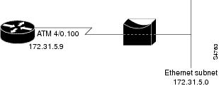
For situations in which a routed network needs connectivity to a remote bridged Ethernet network, a serial or ISDN interface can be configured to function as a PPP half-bridge. The line to the remote bridge functions as a virtual Ethernet interface, and the serial or ISDN interface on the router functions as a node on the same Ethernet subnetwork as the remote network.
The bridge sends bridge packets to the PPP half-bridge, which converts them to routed packets and forwards them to other router processes. Likewise, the PPP half-bridge converts routed packets to Ethernet bridge packets and sends them to the bridge on the same Ethernet subnetwork.
Note
Figure 91 shows a router with a serial interface configured as a PPP half-bridge. The interface functions as a node on the Ethernet subnetwork with the bridge. Note that the serial interface has an IP address on the same Ethernet subnetwork as the bridge.
Figure 91 Router Serial Interface Configured as a Half-Bridge
Note
To configure a serial interface to function as a half-bridge, use the following commands beginning in global configuration mode as appropriate for your network:
Note
For more information about AppleTalk addressing, refer to the "Configuring AppleTalk" chapter of the Cisco IOS AppleTalk and Novell IPX Configuration Guide. For more information about IPX addresses and encapsulations, refer to the "Configuring Novell IPX" chapter of the Cisco IOS AppleTalk and Novell IPX Configuration Guide.
Configuring Multilink PPP
The Multilink PPP feature provides load balancing functionality over multiple WAN links, while providing multivendor interoperability, packet fragmentation and proper sequencing, and load calculation on both inbound and outbound traffic. The Cisco implementation of MLP supports the fragmentation and packet sequencing specifications in RFC 1990. Additionally, you can change the default endpoint discriminator value that is supplied as part of user authentication. Refer to RFC 1990 for more information about the endpoint discriminator.
MLP allows packets to be fragmented and the fragments to be sent at the same time over multiple point-to-point links to the same remote address. The multiple links come up in response to a defined dialer load threshold. The load can be calculated on inbound traffic, outbound traffic, or on either, as needed for the traffic between the specific sites. MLP provides bandwidth on demand and reduces transmission latency across WAN links.
MLP is designed to work over synchronous and asynchronous serial and BRI and PRI types of single or multiple interfaces that have been configured to support both dial-on-demand rotary groups and PPP encapsulation.
Perform the tasks in the following sections, as required for your network, to configure MLP:
•
•
•
•
•
•
Configuring MLP on Synchronous Interfaces
To configure Multilink PPP on synchronous interfaces, you configure the synchronous interfaces to support PPP encapsulation and Multilink PPP.
To configure a synchronous interface, use the following commands beginning in global configuration mode:
Repeat these steps for additional synchronous interfaces, as needed.
Configuring MLP on Asynchronous Interfaces
To configure MLP on asynchronous interfaces, configure the asynchronous interfaces to support dial-on-demand routing (DDR) and PPP encapsulation, and then configure a dialer interface to support PPP encapsulation, bandwidth on demand, and Multilink PPP.
To configure an asynchronous interface to support DDR and PPP encapsulation, use the following commands beginning in global configuration mode:
Repeat these steps for additional asynchronous interfaces, as needed.
At some point, adding more asynchronous interfaces does not improve performance, With the default maximum transmission unit (MTU) size, MLP should support three asynchronous interfaces using V.34 modems. However, packets might be dropped occasionally if the maximum transmission unit (MTU) size is small or large bursts of short frames occur.
To configure a dialer interface to support PPP encapsulation and Multilink PPP, use the following commands beginning in global configuration mode:
Configuring MLP on a Single ISDN BRI Interface
To enable MLP on a single ISDN BRI interface, you are not required to define a dialer rotary group separately because ISDN interfaces are dialer rotary groups by default.
To enable PPP on an ISDN BRI interface, use the following commands beginning in global configuration mode:
If you do not use PPP authentication procedures (Step 8), your telephone service must pass caller ID information.
The load threshold number is required. For an example of configuring MLP on a single ISDN BRI interface, see the section "MLP on One ISDN BRI Interface Example" at the end of this chapter.
When MLP is configured and you want a multilink bundle to be connected indefinitely, use the dialer idle-timeout command to set a very high idle timer. (The dialer-load threshold 1 command no longer keeps a multilink bundle of n links connected indefinitely, and the dialer-load threshold 2 command no longer keeps a multilink bundle of two links connected indefinitely.)
Configuring MLP on Multiple ISDN BRI Interfaces
To enable MLP on multiple ISDN BRI interfaces, set up a dialer rotary interface and configure it for Multilink PPP, and then configure the BRI interfaces separately and add them to the same rotary group.
To set up the dialer rotary interface for the BRI interfaces, use the following commands beginning in global configuration mode:
If you do not use PPP authentication procedures (Step 10), your telephone service must pass caller ID information.
To configure each of the BRI interfaces to belong to the same rotary group, use the following commands beginning in global configuration mode:
Repeat Steps 1 through 6 for each BRI that you want to belong to the same dialer rotary group.
When MLP is configured and you want a multilink bundle to be connected indefinitely, use the dialer idle-timeout command to set a very high idle timer. (The dialer load-threshold 1 command no longer keeps a multilink bundle of n links connected indefinitely and the dialer load-threshold 2 command no longer keeps a multilink bundle of two links connected indefinitely.)
Note
For an example of configuring MLP on multiple ISDN BRI interfaces, see the section "MLP on Multiple ISDN BRI Interfaces Example" at the end of this chapter.
Configuring MLP Using Multilink Group Interfaces
MLP can be configured by assigning a multilink group to a virtual template configuration. Virtual templates allow a virtual access interface to dynamically clone interface parameters from the specified virtual template. If a multilink group is assigned to a virtual template, and then the virtual template is assigned to a physical interface, all links that pass through the physical interface will belong to the same multilink bundle.
A multilink group interface configuration will override a global multilink virtual template configured with the multilink virtual template command.
Multilink group interfaces can be used with ATM, PPP over Frame Relay, and serial interfaces.
To configure MLP using a multilink group interface, perform the following tasks:
•
•
•
To configure the multilink group, use the following commands beginning in global configuration mode:
To assign the multilink group to a virtual template, perform the following task beginning in global configuration mode:
To configure the physical interface and assign the virtual template to it, perform the following task beginning in global configuration mode. This example is for an ATM interface. However, multilink group interfaces can also be used with PPP over Frame Relay interfaces and serial interfaces.
To see an example of how to configure MLP over an ATM PVC using a multilink group, see the section "MLP Using Multilink Group Interfaces over ATM Example" at the end of this chapter.
Changing the Default Endpoint Discriminator
By default, when the system negotiates use of MLP with the peer, the value that is supplied for the endpoint discriminator is the same as the username used for authentication. That username is configured for the interface by the Cisco IOS ppp chap hostname or ppp pap sent-username command, or defaults to the globally configured host name (or stack group name, if this interface is a Stack Group Bidding Protocol, or SGBP, group member).
To override or change the default endpoint discriminator, use the following command in interface configuration mode:
To see an example of how to change the default endpoint discriminator, see the section "Changing the Default Endpoint Discriminator Example" at the end of this chapter.
Configuring MLP Interleaving and Queueing
Interleaving on MLP allows large packets to be multilink encapsulated and fragmented into a small enough size to satisfy the delay requirements of real-time traffic; small real-time packets are not multilink encapsulated and are sent between fragments of the large packets. The interleaving feature also provides a special transmit queue for the smaller, delay-sensitive packets, enabling them to be sent earlier than other flows.
Weighted fair queueing on MLP works on the packet level, not at the level of multilink fragments. Thus, if a small real-time packet gets queued behind a larger best-effort packet and no special queue has been reserved for real-time packets, the small packet will be scheduled for transmission only after all the fragments of the larger packet are scheduled for transmission.
Weighted fair queueing is now supported on all interfaces that support Multilink PPP, including MLP virtual access interfaces and virtual interface templates. Weighted fair-queueing is enabled by default.
Fair queueing on MLP overcomes a prior restriction. Previously, fair queueing was not allowed on virtual access interfaces and virtual interface templates. Interleaving provides the delay bounds for delay-sensitive voice packets on a slow link that is used for other best-effort traffic.
Interleaving applies only to interfaces that can configure a multilink bundle interface. These restrictions include virtual templates, dialer interfaces, and ISDN BRI or PRI interfaces.
Multilink and fair queueing are not supported when a multilink bundle is off-loaded to a different system using Multichassis Multilink PPP (MMP). Thus, interleaving is not supported in MMP networking designs.
MLP support for interleaving can be configured on virtual templates, dialer interfaces, and ISDN BRI or PRI interfaces. To configure interleaving, complete the following tasks:
•
•
Note
Configuring MLP Interleaving
To configure MLP and interleaving on a configured and operational interface or virtual interface template, use the following commands beginning in interface configuration mode:
Step 1
Router(config-if)# ppp multilink
Enables Multilink PPP.
Step 2
Router(config-if)# ppp multilink interleave
Enables interleaving of packets among the fragments of larger packets on an MLP bundle.
Step 3
Router(config-if)# ppp multilink fragment delay milliseconds
Specifies a maximum size, in units of time, for packet fragments on an MLP bundle.
Step 4
Router(config-if)# ip rtp reserve lowest-udp-port range-of-ports [maximum-bandwidth]
Reserves a special queue for real-time packet flows to specified destination UDP ports, allowing real-time traffic to have higher priority than other flows.
Step 5
Router(config-if)# exit
Exits interface configuration mode.
Step 6
Router(config)# multilink virtual-template 1
For virtual templates only, applies the virtual template to the multilink bundle.1
1 This step is not used for ISDN or dialer interfaces.
Interleaving statistics can be displayed by using the show interfaces command, specifying the particular interface on which interleaving is enabled. Interleaving data is displayed only if there are interleaves. For example, the following line shows interleaves:
Output queue: 315/64/164974/31191 (size/threshold/drops/interleaves)Configuring MLP Inverse Multiplexer and Distributed MLP
The distributed MLP feature combines T1/E1 lines in a VIP on a Cisco 7500 series router into a bundle that has the combined bandwidth of the multiple T1/E1 lines. This is done using a VIP MLP link. You choose the number of bundles and the number of T1/E1 lines in each bundle, which allows you to increase the bandwidth of your network links beyond that of a single T1/E1 line without having to purchase a T3 line.
Nondistributed MLP can only perform limited links, with CPU usage quickly reaching 90% with only a few T1/E1 lines running MLP. With distributed MLP, you can increase the router's total capacity.
The MLP Inverse Multiplexer feature was designed for Internet service providers (ISPs) that want to have the bandwidth of multiple T1 lines with performance comparable to that of an inverse multiplexer without the need of buying standalone inverse-multiplexing equipment. A Cisco router supporting VIPs can bundle multiple T1 lines in a CT3 or CE3 interface. Bundling is more economical than purchasing an inverse multiplexer, and eliminates the need to configure another piece of equipment.
This feature supports the CT3 CE3 data rates without taxing the RSP and CPU by moving the data path to the VIP. This feature also allows remote sites to purchase multiple T1 lines instead of a T3 line, which is especially useful when the remote site does not need the bandwidth of an entire T3 line.
This feature allows multilink fragmentation to be disabled, so multilink packets are sent using Cisco Express Forwarding (CEF) on all platforms, if fragmentation is disabled. CEF is now supported with fragmentation enabled or disabled.
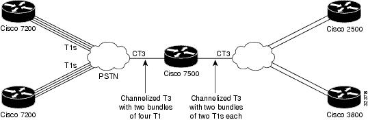
Figure 92 shows a typical network using a VIP MLP link. The Cisco 7500 series router is connected to the network with a CT3 line that has been configured with VIP MLP to carry two bundles of four T1 lines each. One of these bundles goes out to a Cisco 2500 series router and the other goes out to a Cisco 3800 series router.
Figure 92 Diagram of a Typical VIP MLP Topology
Before beginning the MLP Inverse Multiplexer configuration tasks, make note of the following prerequisites and restrictions.
Prerequisites
•
•
–
–
–
–
–
–
–
•
Restrictions
•
•
•
•
•
•
•
•
•
•
•
•
•
•
•
•
•
•
•
Enabling fragmentation reduces the delay latency among bundle links, but adds some load to the CPU. Disabling fragmentation may result in better throughput.
If your data traffic is consistently of a similar size, we recommend disabling fragmentation. In this case, the benefits of fragmentation may be outweighed by the added load on the CPU.
To configure a multilink bundle, perform the tasks in the following sections:
•
•
•
•
•
Enabling Distributed CEF Switching
To enable distributed MLP, first enable distributed CEF (dCEF) switching using the following command in global configuration mode:
Creating a Multilink Bundle
To create a multilink bundle, use the following commands beginning in global configuration mode:
Assigning an Interface to a Multilink Bundle
To assign an interface to a multilink bundle, use the following commands in interface configuration mode:
Disabling PPP Multilink Fragmentation
By default, PPP multilink fragmentation is enabled. To disable PPP multilink fragmentation, use the following command in interface configuration mode:
Router(config-if)# ppp multilink fragment disable
(Optional) Disables PPP multilink fragmentation.
Verifying the MLP Inverse Multiplexer Configuration
To display information about the newly created multilink bundle, use the show ppp multilink command in EXEC mode:
Router# show ppp multilinkMultilink1, bundle name is group1Bundle is Distributed0 lost fragments, 0 reordered, 0 unassigned, sequence 0x0/0x0 rcvd/sent0 discarded, 0 lost received, 1/255 loadMember links:4 active, 0 inactive (max not set, min not set)Serial1/0/0:1Serial1/0/0/:2Serial1/0/0/:3Serial1/0/0/:4Monitoring and Maintaining PPP and MLP Interfaces
To monitor and maintain virtual interfaces, use the following command in EXEC mode:
Configuration Examples for PPP and MLP
The following sections provide various PPP configuration examples:
•
•
•
•
•
•
CHAP with an Encrypted Password Examples
The following examples show how to enable CHAP on serial interface 0 of three devices:
Configuration of Router yyy
hostname yyyinterface serial 0encapsulation pppppp authentication chapusername xxx password secretxyusername zzz password secretzyConfiguration of Router xxx
hostname xxxinterface serial 0encapsulation pppppp authentication chapusername yyy password secretxyusername zzz password secretxzConfiguration of Router zzz
hostname zzzinterface serial 0encapsulation pppppp authentication chapusername xxx password secretxzusername yyy password secretzyWhen you look at the configuration file, the passwords will be encrypted and the display will look similar to the following:
hostname xxxinterface serial 0encapsulation pppppp authentication chapusername yyy password 7 121F0A18username zzz password 7 1329A055User Maximum Links Configuration Example
The following example shows how to configure the username sTephen and establish a maximum of five connections. sTephen can connect through serial interface 1/0, which has a dialer map configured for it, or through PRI interface 0/0:23, which has dialer profile interface 0 dedicated to it.
The aaa authorization network default local command must be configured. PPP encapsulation and authentication must be enabled on all the interfaces that sTephen can connect to.
aaa new-modelaaa authorization network default localenable secret saintstephenenable password witharose!username sTephen user-maxlinks 5 password gardenhegoes!interface Serial0/0:23no ip addressencapsulation pppdialer pool-member 1ppp authentication chapppp multilink!interface Serial1/0ip address 10.2.2.4 255.255.255.0encapsulation pppdialer in-banddialer map ip 10.2.2.13 name sTephen 12345dialer-group 1ppp authentication chap!interface Dialer0ip address 10.1.1.4 255.255.255.0encapsulation pppdialer remote-name sTephendialer string 23456dialer pool 1dialer-group 1ppp authentication chapppp multilink!dialer-list 1 protocol ip permitMPPC Interface Configuration Examples
The following example configures asynchronous interface 1 to implement MPPC and ignore the protocol field compression flag negotiated by LCP:
interface async1ip unnumbered ethernet0encapsulation pppasync default routingasync dynamic routingasync mode interactivepeer default ip address 172.21.71.74compress mppc ignore-pfcThe following example creates a virtual access interface (virtual-template interface 1) and serial interface 0, which is configured for X.25 encapsulation. MPPC values are configured on the virtual-template interface and will ignore the negotiated protocol field compression flag.
interface ethernet0ip address 172.20.30.102 255.255.255.0!interface virtual-template1ip unnumbered ethernet0peer default ip address pool vtemp1compress mppc ignore-pfc!interface serial0no ipaddressno ip mroute-cacheencapsulation x25x25 win 7x25 winout 7x25 ips 512x25 ops 512clock rate 50000!ip local pool vtemp1 172.20.30.103 172.20.30.104ip route 0.0.0.0 0.0.0.0 172.20.30.1!translate x25 31320000000000 virtual-template 1IP Address Pooling Example
The following example configures a modem to dial in to a Cisco access server and obtain an IP address from the DHCP server. This configuration allows the user to log in and browse an NT network. Notice that the dialer 1 and group-async 1 interfaces are configured with the ip unnumbered loopback command, so that the broadcast can find the dialup clients and the client can see the NT network.
!hostname secret!aaa new-modelaaa authentication login default localaaa authentication ppp default if-needed localaaa authentication ppp chap localenable secret 5 encrypted-secretenable password EPassWd1!username User1 password 0 PassWd2username User2 password 0 PassWd3username User3 password 0 PassWd4no ip domain-lookupip dhcp-server 10.47.0.131async-bootp gateway 10.47.0.1async-bootp nbns-server 10.47.0.131isdn switch-type primary-4ess!!controller t1 0framing esfclock source line primarylinecode b8zspri-group timeslots 1-24!controller t1 1framing esfclock source line secondarylinecode b8zs!interface loopback 0ip address 10.47.252.254 255.255.252.0!interface ethernet 0ip address 10.47.0.5 255.255.252.0ip helper-address 10.47.0.131ip helper-address 10.47.0.255no ip route-cacheno ip mroute-cache!interface serial 0no ip addressno ip mroute-cacheshutdown!interface serial 1no ip addressshutdown!interface serial 0:23no ip addressencapsulation pppno ip mroute-cachedialer rotary-group 1dialer-group 1isdn incoming-voice modemno fair-queueno cdp enable!interface group-async 1ip unnumbered loopback 0ip helper-address 10.47.0.131ip tcp header-compression passiveencapsulation pppno ip route-cacheno ip mroute-cacheasync mode interactivepeer default ip address dhcpno fair-queueno cdp enableppp authentication chapgroup-range 1 24!interface dialer 1ip unnumbered loopback 0encapsulation pppdialer in-banddialer-group 1no peer default ip addressno fair-queueno cdp enableppp authentication chapppp multilink!router ospf 172redistribute connected subnetsredistribute staticnetwork 10.47.0.0 0.0.3.255 area 0network 10.47.156.0 0.0.3.255 area 0network 10.47.168.0 0.0.3.255 area 0network 10.47.252.0 0.0.3.255 area 0!ip local pool RemotePool 10.47.252.1 10.47.252.24ip classlessip route 10.0.140.0 255.255.255.0 10.59.254.254ip route 10.2.140.0 255.255.255.0 10.59.254.254ip route 10.40.0.0 255.255.0.0 10.59.254.254ip route 10.59.254.0 255.255.255.0 10.59.254.254ip route 172.23.0.0 255.255.0.0 10.59.254.254ip route 192.168.0.0 255.255.0.0 10.59.254.254ip ospf name-lookupno logging bufferedaccess-list 101 deny ip any host 255.255.255.255access-list 101 deny ospf any anyaccess-list 101 permit ip any anydialer-list 1 protocol ip list 101snmp-server community public RO!line con 0line 1 24autoselect during-loginautoselect pppmodem InOuttransport input allline aux 0line vty 0 4password PassWd5!scheduler interval 100endDHCP Network Control Example
The following partial example adds the ip dhcp-client network-discovery command to the previous "IP Address Pooling Example" to allow peer routers to more dynamically discover DNS and NetBIOS name servers. If the ip dhcp-client network-discovery command is disabled, the system falls back to the static configurations made using the async-bootp dns-server and async-bootp nb-server global configuration commands.
!hostname secret!aaa new-modelaaa authentication login default localaaa authentication ppp default if-needed localaaa authentication ppp chap localenable secret 5 encrypted-secretenable password EPassWd1!username User1 password 0 PassWd2username User2 password 0 PassWd3username User3 password 0 PassWd4no ip domain-lookupip dhcp-server 10.47.0.131ip dhcp-client network-discovery informs 2 discovers 2 period 12async-bootp gateway 10.47.0.1async-bootp nbns-server 10.47.0.131isdn switch-type primary-4ess...PPP Reliable Link Examples
The following example enables PPP reliable link and STAC compression on BRI 0:
interface BRI0description Enables stac compression on BRI 0ip address 172.1.1.1 255.255.255.0encapsulation pppdialer map ip 172.1.1.2 name baseball 14195386368compress stacppp authentication chapdialer-group 1ppp reliable-linkThe following example shows output of the show interfaces command when PPP reliable link is enabled. The LAPB output lines indicate that PPP reliable link is provided over LAPB.
Router# show interfaces serial 0Serial0 is up, line protocol is upHardware is HD64570Description: connects to enkidu s 0Internet address is 172.21.10.10/8MTU 1500 bytes, BW 1544 Kbit, DLY 20000 usec, rely 255/255, load 1/255Encapsulation PPP, loopback not setLCP OpenOpen: IPCP, CDPLAPB DTE, state CONNECT, modulo 8, k 7, N1 12048, N2 20T1 3000, T2 0, interface outage (partial T3) 0, T4 0, PPP over LAPBVS 1, VR 1, tx NR 1, Remote VR 1, Retransmissions 0Queues: U/S frames 0, I frames 0, unack. 0, reTx 0IFRAMEs 1017/1017 RNRs 0/0 REJs 0/0 SABM/Es 1/1 FRMRs 0/0 DISCs 0/0Last input 00:00:18, output 00:00:08, output hang neverLast clearing of "show interface" counters neverInput queue: 0/75/0 (size/max/drops); Total output drops: 0Queueing strategy: weighted fairOutput queue: 0/64/0 (size/threshold/drops)Conversations 0/1 (active/max active)Reserved Conversations 0/0 (allocated/max allocated)5 minute input rate 3000 bits/sec, 4 packets/sec5 minute output rate 3000 bits/sec, 7 packets/sec1365 packets input, 107665 bytes, 0 no bufferReceived 0 broadcasts, 0 runts, 0 giants, 0 throttles0 input errors, 0 CRC, 0 frame, 0 overrun, 0 ignored, 0 abort2064 packets output, 109207 bytes, 0 underruns0 output errors, 0 collisions, 4 interface resets0 output buffer failures, 0 output buffers swapped out4 carrier transitionsDCD=up DSR=up DTR=up RTS=up CTS=upMLP Examples
This section contains the following MLP examples:
•
•
•
•
•
MLP on Synchronous Serial Interfaces Example
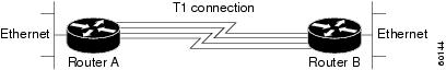
MLP provides characteristics most similar to hardware inverse multiplexers, with good manageability and Layer 3 services support. Figure 93 shows a typical inverse multiplexing application using two Cisco routers and Multilink PPP over four T1 lines.
Figure 93 Inverse Multiplexing Application Using Multilink PPP
The following example shows the configuration commands used to create the inverse multiplexing application:
Router A Configuration
hostname RouterA!!username RouterB password your_passwordip subnet-zeromultilink virtual-template 1!interface Virtual-Template1ip unnumbered Ethernet0ppp authentication chapppp multilink!interface Serial0no ip addressencapsulation pppno fair-queueppp multilinkpulse-time 3!interface Serial1no ip addressencapsulation pppno fair-queueppp multilinkpulse-time 3!interface Serial2no ip addressencapsulation pppno fair-queueppp multilinkpulse-time 3!interface Serial3no ip addressencapsulation pppno fair-queueppp multilinkpulse-time 3!interface Ethernet0ip address 10.17.1.254 255.255.255.0!router ripnetwork 10.0.0.0!endRouter B Configuration
hostname RouterB!!username RouterB password your_passwordip subnet-zeromultilink virtual-template 1!interface Virtual-Template1ip unnumbered Ethernet0ppp authentication chapppp multilink!interface Serial0no ip addressencapsulation pppno fair-queueppp multilinkpulse-time 3!interface Serial1no ip addressencapsulation pppno fair-queueppp multilinkpulse-time 3!interface Serial2no ip addressencapsulation pppno fair-queueppp multilinkpulse-time 3!interface Serial3no ip addressencapsulation pppno fair-queueppp multilinkpulse-time 3!interface Ethernet0ip address 10.17.2.254 255.255.255.0!router ripnetwork 10.0.0.0!endMLP on One ISDN BRI Interface Example
The following example enables MLP on BRI interface 0. Because an ISDN interface is a rotary group by default, when one BRI is configured, no dialer rotary group configuration is required.
interface bri 0description connected to ntt 81012345678902ip address 172.31.1.7 255.255.255.0encapsulation pppdialer idle-timeout 30dialer load-threshold 40 eitherdialer map ip 172.31.1.8 name atlanta 81012345678901dialer-group 1ppp authentication papppp multilinkMLP on Multiple ISDN BRI Interfaces Example
The following example configures multiple ISDN BRI interfaces to belong to the same dialer rotary group for Multilink PPP. The dialer rotary-group command is used to assign each of the ISDN BRI interfaces to that dialer rotary group.
interface BRI0no ip addressencapsulation pppdialer idle-timeout 500dialer rotary-group 0dialer load-threshold 30 either!interface BRI1no ip addressencapsulation pppdialer idle-timeout 500dialer rotary-group 0dialer load-threshold 30 either!interface BRI2no ip addressencapsulation pppdialer idle-timeout 500dialer rotary-group 0dialer load-threshold 30 either!interface Dialer0ip address 10.0.0.2 255.0.0.0encapsulation pppdialer in-banddialer idle-timeout 500dialer map ip 10.0.0.1 name atlanta broadcast 81012345678901dialer load-threshold 30 eitherdialer-group 1ppp authentication chapppp multilinkMLP Using Multilink Group Interfaces over ATM Example
The following example configures MLP over an ATM PVC using a multilink group:
interface multilink 1ip address 10.200.83.106 255.255.255.252ip tcp header-compression iphc-format delay 20000service policy output xyzencapsulation pppppp multilinkppp multilink fragment delay 10ppp multilink interleaveppp timeout multilink link remove 10ip rtp header-compression iphc-formatinterface virtual-template 3bandwidth 128ppp multilink group 1interface atm 4/0.1 point-to-pointpvc 0/32abr 100 80protocol ppp virtual-template 3Changing the Default Endpoint Discriminator Example
The following partial example changes the MLP endpoint discriminator from the default CHAP host name C-host1 to the E.164-compliant telephone number 1 603 555-1212:
...interface dialer 0ip address 10.1.1.4 255.255.255.0encapsulation pppdialer remote-name R-host1dialer string 23456dialer pool 1dialer-group 1ppp chap hostname C-host1ppp multilink endpoint phone 16035551212...MLP Interleaving and Queueing for Real-Time Traffic Example
The following example defines a virtual interface template that enables MLP interleaving and a maximum real-time traffic delay of 20 milliseconds, and then applies that virtual template to the MLP bundle:
interface virtual-template 1ip unnumbered ethernet 0ppp multilinkppp multilink interleaveppp multilink fragment delay 20ip rtp interleave 32768 20 1000multilink virtual-template 1The following example enables MLP interleaving on a dialer interface that controls a rotary group of BRI interfaces. This configuration permits IP packets to trigger calls.
interface BRI 0description connected into a rotary groupencapsulation pppdialer rotary-group 1!interface BRI 1no ip addressencapsulation pppdialer rotary-group 1!interface BRI 2encapsulation pppdialer rotary-group 1!interface BRI 3no ip addressencapsulation pppdialer rotary-group 1!interface BRI 4encapsulation pppdialer rotary-group 1!interface Dialer 0description Dialer group controlling the BRIsip address 10.1.1.1 255.255.255.0encapsulation pppdialer map ip 10.1.1.2 name angus 14802616900dialer-group 1ppp authentication chap! Enables Multilink PPP interleaving on the dialer interface and reserves! a special queue.ppp multilinkppp multilink interleaveip rtp reserve 32768 20 1000! Keeps fragments of large packets small enough to ensure delay of 20 ms or less.ppp multilink fragment delay 20dialer-list 1 protocol ip permitT3 Controller Configuration for an MLP Multilink Inverse Multiplexer Example
In the following example, the T3 controller is configured and four channelized interfaces are created:
controller T3 1/0/0framing m23cablelength 10t1 1 timeslots 1-24t1 2 timeslots 1-24t1 3 timeslots 1-24t1 4 timeslots 1-24Multilink Interface Configuration for Distributed MLP Example
In the following example, four multilink interfaces are created with distributed CEF switching and MLP enabled. Each of the newly created interfaces is added to a multilink bundle.
interface multilink1ip address 10.0.0.0 10.255.255.255ppp chap hosstname group 1ppp multilinkppp multilink group 1interface serial 1/0/0/:1no ip addressencapsulation pppip route-cache distributedno keepaliveppp multilinkppp multilink group 1interface serial 1/0/0/:2no ip addressencapsulation pppip route-cache distributedno keepaliveppp chap hostname group 1ppp multilinkppp multilink group 1interface serial 1/0/0/:3no ip addressencapsulation pppip route-cache distributedno keepaliveppp chap hostname group 1ppp multilinkppp multilink group 1interface serial 1/0/0/:4no ip addressencapsulation pppip route-cache distributedno keepaliveppp chap hostname group 1ppp multilinkppp multilink group 1