-
Cisco IOS Dial Technologies Configuration Guide, Release 12.2
-
About Cisco IOS Software Documentation
-
Using Cisco IOS Software
- Part 1: Dial Interfaces, Controllers, and Lines
- Part 2: Modem Configuration Management
- Part 3: ISDN Configuration
- Part 4: Signaling Configuration
- Part 5: Dial-on-Demand Routing Configuration
- Part 6: Dial-Backup Configuration
- Part 7: Dial-Related Addressing Services
- Part 8: Virtual Templates, Profiles, and Networks
- Part 9: PPP Configuration
- Part 10: Callback and Bandwidth Allocation Configuration
- Part 11: Dial Access Specialized Features
- Part 12: Dial Access Scenarios
- Part 13: Appendix
-
 Feedback
Table Of Contents
Configuring Multichassis Multilink PPP
Multichassis Multilink PPP Overview
Configuring the Stack Group and Identifying Members
Configuring a Virtual Template and Creating a Virtual Template Interface
Monitoring and Maintaining MMP Virtual Interfaces
Configuration Examples for MMP
MMP with Explicitly Defined Dialer
MMP with ISDN PRI but No Explicitly Defined Dialer
Configuring Multichassis Multilink PPP
This chapter describes how to configure Multichassis Multilink PPP (MLP). It includes the following main sections:
•
Multichassis Multilink PPP Overview
•
•
To identify the hardware platform or software image information associated with a feature, use the Feature Navigator on Cisco.com to search for information about the feature or refer to the software release notes for a specific release. For more information, see the "Identifying Supported Platforms" section in the "Using Cisco IOS Software" chapter.
For a complete description of the MMP commands mentioned in this chapter, refer to the Cisco IOS Dial Technologies Command Reference, Release 12. To locate documentation of other commands that appear in this chapter, use the command reference master index or search online.
Multichassis Multilink PPP Overview
Prior to Release 11.2, Cisco IOS supported Multilink PPP (MLP). Beginning with Release 11.2, Cisco IOS software also supports Multichassis Multilink PPP (MMP).
MLP provides the capability of splitting and recombining packets to a single end system across a logical pipe (also called a bundle) formed by multiple links. MMP provides bandwidth on demand and reduces transmission latency across WAN links.
MMP, however, provides the additional capability for links to terminate at multiple routers with different remote addresses. MMP can also handle both analog and digital traffic.
MLP is intended for situations with large pools of dial-in users, in which a single chassis cannot provide enough dial ports. This feature allows companies to provide a single dialup number to its users and to apply the same solution to analog and digital calls. This feature allows Internet service providers (ISPs), for example, to allocate a single ISDN rotary number to several ISDN PRIs across several routers. This capability allows for easy expansion and scalability and for assured fault tolerance and redundancy.
MMP allows network access servers to be stacked together and to appear as a single network access server chassis so that if one network access server fails, another network access server in the stack can accept calls.
With large-scale dial-out, these features are available for both outgoing and incoming calls.
Stack Groups
Routers or access servers are configured to belong to groups of peers called stack groups. All members of the stack group are peers; stack groups do not need a permanent lead router. Any stack group member can answer calls coming from a single access number, which is usually an ISDN PRI hunt group. Calls can come in from remote user devices, such as routers, modems, ISDN terminal adapters, and PC cards.
Once a connection is established with one member of a stack group, that member owns the call. If a second call comes in from the same client and a different router answers the call, the router establishes a tunnel and forwards all packets that belong to the call to the router that owns the call. Establishing a tunnel and forwarding calls through it to the router that owns the call is sometimes called projecting the PPP link to the call master.
If a more powerful router is available, it can be configured as a member of the stack group and the other stack group members can establish tunnels and forward all calls to it. In such a case, the other stack group members are just answering calls and forwarding traffic to the more powerful offload router.
Note
Call Handling and Bidding
MMP call handling, bidding, and Layer 2 forwarding operations in the stack group proceed as follows:
1.
2.
3.
4.
5.
6.
7.
8.
9.
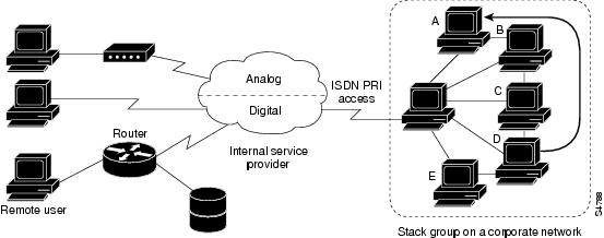
Figure 94 shows the call handling an bidding process in a typical MLP scenario.
Figure 94 Typical MLP Scenario
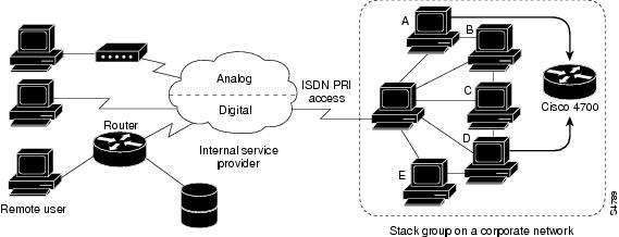
In contrast to Figure 94, Figure 95 features an offload router. Access servers that belong to a stack group answer calls, establish tunnels, and forward calls to a Cisco 4700 router that wins the bidding and is the call master for all the calls. The Cisco 4700 reassembles and resequences all the packets that come in through the stack group.
Figure 95 MLP with an Offload Router as a Stack Group Member
Note
MMP support on a group of routers requires that each router be configured to support the following:
•
•
•
MMP is supported on the Cisco 2500, 4500, and 7500 series platforms and on synchronous serial, asynchronous serial, ISDN BRI, ISDN PRI, and dialer interfaces.
MMP does not require reconfiguration of telephone company switches.
Dialer profiles are not supported for SGBP (Stack Group Bidding Protocol).
How to Configure MMP
To configure MMP, perform the tasks in the following sections, in the order listed:
•
•
See the section "Monitoring and Maintaining MMP Virtual Interfaces" later in this chapter for tips on maintaining MMP. See the examples in the section "Configuration Examples for MMP" later in this chapter for ideas on how to configure MMP in your network.
Configuring the Stack Group and Identifying Members
To configure the stack group on the router, use the following commands in global configuration mode:
Repeat these steps for each additional stack group peer.
Note
Configuring a Virtual Template and Creating a Virtual Template Interface
You need to configure a virtual template for MMP when asynchronous or synchronous serial interfaces are used, but dialers are not defined. When dialers are configured on the physical interfaces, do not specify a virtual template interface.
To configure a virtual template for any nondialer interfaces, use the following commands beginning in global configuration mode:
If dialers are or will be configured on the physical interfaces, the ip unnumbered command, mentioned in Step 4, will be used in configuring the dialer interface. For examples that show MMP configured with and without dialers, see the "Configuration Examples for MMP" at the end of this chapter.
Note
For more information about address pooling, see the "Configuring Media-Independent PPP and Multilink PPP" chapter.
Monitoring and Maintaining MMP Virtual Interfaces
To monitor and maintain virtual interfaces, use any of the following commands in EXEC mode:
Configuration Examples for MMP
The following sections provide w MMP configuration examples without and with dialers:
MMP Using PRI But No Dialers
The following example shows the configuration of MMP when no dialers are involved. Comments in the configuration discuss the commands. Variations are shown for a Cisco AS5200 access server or Cisco 4000 series router and for an E1 or T1 controller.
sgbp group stackqsgbp member systemb 10.1.1.2sgbp member systemc 10.1.1.3username stackq password therock! First make sure the multilink virtual template number is defined globally on¡ each router that is a member of the stack group.multilink virtual-template 1! If you have not configured any dialer interfaces for the physical interfaces in! question (PRI, BRI, async, sync serial), you can define a virtual template.interface virtual-template 1ip unnumbered e0no ip route-cacheppp authentication chapppp multilink! Never define a specific IP address on the virtual template because projected ! virtual access interfaces are always cloned from the virtual template interface. ! If a subsequent PPP link also gets projected to a stack member with a virtual ! access interface already cloned and active, identical IP addresses will be on ! on the two virtual interfaces. IP will erroneously route between them.! On an AS5200 or 4XXX platform.! On a TI controller.!controller T1 0framing esflinecode b8zspri-group timeslots 1-24!interface serial 0:23no ip addressencapsulation pppno ip route-cacheppp authentication chapppp multilink!! On an E1 controller.!controller E1 0framing crc4linecode hdb3pri-group timeslots 1-31interface serial 0:15no ip addressencapsulation pppno ip route-cacheppp authentication chapppp multilinkMMP with Dialers
When dialers are configured on the physical interfaces and when the interface itself is a dialer, do not specify a virtual template interface. For dialers, you only need to define the stack group name, common password, and its members across all the stack members. No virtual template interface is defined at all.
Only the PPP commands in dialer interface configuration are applied to the bundle interface. Subsequent projected PPP links are also cloned with the PPP commands from the dialer interface.
Dialer profiles are not supported for SGBP (Stack Group Bidding Protocol).
This section includes the following examples:
•
•
MMP with Explicitly Defined Dialer
The following example includes a dialer that is explicitly specified by the interface dialer command and configured by the commands that immediately follow:
sgbp group stackqsgbp member systemb 10.1.1.2sgbp member systemc 10.1.1.3username stackq password therockinterface dialer 1ip unnumbered e0dialer map .....encapsulation pppppp authentication chapdialer-group 1ppp multilink!! On a T1 controllercontroller T1 0framing esflinecode b8zspri-group timeslots 1-24interface Serial0:23no ip addressencapsulation pppdialer in-banddialer rotary 1dialer-group 1!! Or on an E1 Controllercontroller E1 0framing crc4linecode hdb3pri-group timeslots 1-31interface serial 0:15no ip addressencapsulation pppno ip route-cacheppp authentication chapppp multilinkMMP with ISDN PRI but No Explicitly Defined Dialer
ISDN PRIs and BRIs by default are dialer interfaces. That is, a PRI configured without an explicit interface dialer command is still a dialer interface. The following example configures ISDN PRI. The D-channel configuration on serial interface 0:23 is applied to all the B channels. MMP is enabled, but no virtual interface template needs to be defined.
sgbp group stackqsgbp member systemb 10.1.1.2sgbp member systemc 10.1.1.3username stackq password therockisdn switch-type primary-4esscontroller t1 0framing esflinecode b8zspri-group timeslots 1-23isdn switch-type basic-net3interface Serial0:23ip unnumbered e0dialer map .....encap pppppp authentication chapdialer-group 1dialer rot 1!ppp multilinkMMP with Offload Server
The following example shows a virtual template interface for a system that is being configured as an offload server (via the sgbp seed-bid offload command). All other stack group members must be defined with the sgbp seed-bid default command (or if you do not enter any sgbp seed-bid command, it defaults to this command).
multilink virtual-template 1sgbp group stackqsgbp member systemb 10.1.1.2sgbp member systemc 10.1.1.3sgbp seed-bid offloadusername stackq password therockinterface virtual-template 1ip unnumbered e0no ip route-cacheppp authentication chapppp multilink