-
Cisco ASR 1000 Series Aggregation Services Routers SIP and SPA Software Configuration Guide
-
About this Guide
-
Using Cisco IOS Software
-
SIP and SPA Product Overview
- SPA Interface Processor
- ATM Shared Port Adapters
- Ethernet Shared Port Adapters
- Packet over SONET Shared Port Adapters
-
Serial Shared Port Adapters
-
Overview of the Serial SPAs
-
Configuring the 8-Port Channelized T1/E1 SPA
-
Configuring the 2-Port and 4-Port Channelized T3 SPAs
-
Configuring the 2-Port, 4-Port, and 8-Port Clear Channel T3/E3 SPAs
-
Configuring the 4-Port Serial Interface SPA
-
Configuring the 1-Port Channelized OC-3/STM-1 SPA and 1-Port Channelized OC-12/STM-4 SPA
-
Troubleshooting the Serial SPAs
-
- Services Shared Port Adapters
- Field-Programmable Devices
- Quality-of-Service (QoS)
- Circuit Emulation over Packet Shared Port Adapters
-
Glossary
-
 Feedback
Table Of Contents
SONET/SDH Error, Alarm, and Performance Monitoring Features
SONET/SDH Synchronization Features
4-Port OC-3c/STM-1 POS SPA Architecture
Path of a Packet in the Ingress Direction
Path of a Packet in the Egress Direction
2-Port OC-48c/STM-16 POS SPA Architecture
Path of a Packet in the Ingress Direction
Path of a Packet in the Egress Direction
1-Port OC-192c/STM-64 POS/RPR XFP SPA Architecture
Path of a Packet in the Ingress Direction
Path of a Packet in the Egress Direction
Displaying the SPA Hardware Type
Example of the show interfaces Command
Example of the show controllers Command
Overview of the POS SPAs
This chapter provides an overview of the release history, and feature and Management Information Base (MIB) support for the Packet over SONET (POS) SPAs on the Cisco ASR 1000 Series Aggregation Services Routers.
This chapter includes the following sections:
•
Displaying the SPA Hardware Type
Release History
POS Technology Overview
Packet-over-SONET is a high-speed method of transporting IP traffic between two points. This technology combines the Point-to-Point Protocol (PPP), High-level Data Link Control (HDLC), or Frame Relay with Synchronous Optical Network (SONET) and Synchronous Digital Hierarchy (SDH) interfaces.
SONET is an octet-synchronous multiplex scheme defined by the American National Standards Institute (ANSI) standard (T1.1051988) for optical digital transmission at hierarchical rates from 51.840 Mbps to 9.95 Gbps (Synchronous Transport Signal, STS-1 to STS-48) and greater. SDH is an equivalent international standard for optical digital transmission at hierarchical rates from 155.520 Mbps (Synchronous Transfer Mode-1 [STM-1]) to 9.95 Gbps (STM-16) and greater.
SONET specifications have been defined for single-mode fiber and multimode fiber. The POS SPAs allow transmission over single-mode and multimode optical fiber at Optical Carrier 3, 12, 48, and 192 (OC-3, OC-12, OC-48, and OC-192) rates.
SONET/SDH transmission rates are integral multiples of 51.840 Mbps. The following transmission multiples are currently specified and used on the POS SPAs on the Cisco ASR 1000 Series Aggregation Services Routers:
•
•
•
•
Supported Features
•
•
•
SONET/SDH Compliance Features
•
•
•
•
SONET/SDH Error, Alarm, and Performance Monitoring Features
•
•
•
•
•
–
–
–
–
•
–
–
–
–
–
•
–
–
–
–
–
–
–
–
–
SONET/SDH Synchronization Features
•
•
•
WAN Protocol Features
•
•
•
•
•
Network Management Features
•
•
•
•
•
–
–
–
–
–
–
–
–
–
–
–
Restrictions
Note
Table 12-1 provides information about POS feature compatibility and restrictions by SIP and SPA combination.
•
•
Supported MIBs
The following MIBs are supported for the POS SPAs on the Cisco ASR 1000 Series Aggregation Services Routers:
•
•
•
•
•
•
•
•
•
•
To locate and download MIBs for selected platforms, Cisco IOS releases, and feature sets, use Cisco MIB Locator found at the following URL:
http://tools.cisco.com/ITDIT/MIBS/servlet/index
If Cisco MIB Locator does not support the MIB information that you need, you can also obtain a list of supported MIBs and download MIBs from the Cisco MIBs page at the following URL:
http://www.cisco.com/public/sw-center/netmgmt/cmtk/mibs.shtml
To access Cisco MIB Locator, you must have an account on Cisco.com. If you have forgotten or lost your account information, send a blank e-mail to cco-locksmith@cisco.com. An automatic check will verify that your e-mail address is registered with Cisco.com. If the check is successful, account details with a new random password will be e-mailed to you. Qualified users can establish an account on Cisco.com by following the directions found at this URL:
https://tools.cisco.com/RPF/register/register.do
SPA Architecture
This section provides an overview of the architecture of the POS SPAs and describes the path of a packet in the ingress and egress directions. Some of these areas of the architecture are referenced in the SPA software and can be helpful to understand when troubleshooting or interpreting some of the SPA CLI and show command output.
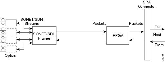
4-Port OC-3c/STM-1 POS SPA Architecture
Figure 12-1 identifies some of the hardware devices that are part of the POS SPA architecture. The figure shows the four ports that are supported by the 4-Port OC-3c/STM-1 POS SPA only.
Figure 12-1 4-Port OC-3c/STM-1 POS SPA Architecture
Every incoming and outgoing packet on the 4-Port OC-3c/STM-1 POS SPA goes through the SONET/SDH framer and field-programmable gate array (FPGA) devices.
Path of a Packet in the Ingress Direction
The following steps describe the path of an ingress packet through the 4-Port OC-3c/STM-1 POS SPA:
1.
2.
3.
4.
Path of a Packet in the Egress Direction
The following steps describe the path of an egress packet through the 4-Port OC-3c/STM-1 POS SPA:
1.
2.
3.
4.
5.
The framer sends the data to the SFP optics for transmission onto the network.
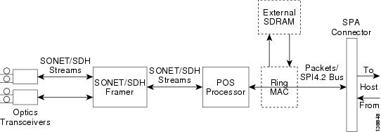
2-Port OC-48c/STM-16 POS SPA Architecture
Figure 12-2 identifies the primary hardware devices that are part of the 2-Port OC-48c/STM-16 POS SPA architecture.
Figure 12-2 2-Port OC-48c/STM-16 POS SPA Architecture
Path of a Packet in the Ingress Direction
The following steps describe the path of an ingress packet through the 2-Port OC-48c/STM-16 POS SPA:
1.
2.
3.
4.
5.
6.
7.
Path of a Packet in the Egress Direction
The following steps describe the path of an egress packet through the 2-Port OC-48c/STM-16 POS SPA:
1.
2.
3.
4.
5.
6.
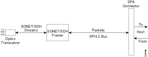
1-Port OC-192c/STM-64 POS/RPR XFP SPA Architecture
Figure 12-3 identifies the primary hardware devices that are part of the POS SPA architecture. The figure shows a single optics transceiver. The 1-Port OC-192c/STM-64 POS/RPR XFP SPA supports XFP optics.
Figure 12-3 1-Port OC-192c/STM-64 POS/RPR XFP SPA Architecture
In POS mode, every incoming and outgoing packet on the OC-192 POS SPAs goes through the SONET/SDH framer and SPI4.2 interface.
Path of a Packet in the Ingress Direction
The following steps describe the path of an ingress packet through the 1-Port OC-192c/STM-64 POS/RPR XFP SPA:
1.
2.
3.
4.
Path of a Packet in the Egress Direction
The following steps describe the path of an egress packet through the 1-Port OC-192c/STM-64 POS/RPR XFP SPA:
1.
2.
3.
4.
5.
6.
Displaying the SPA Hardware Type
To verify information about the SPA hardware that is installed in your Cisco ASR 1000 Series Aggregation Services Routers, you can use the show interfaces command or the show controllers command. There are several other commands on the Cisco ASR 1000 Series Aggregation Services Routers that also provide SPA hardware information. Table 12-2 shows the hardware description that appears in the show command output for each POS SPA that is supported on the Cisco ASR 1000 Series Aggregation Services Routers.
Example of the show interfaces Command
The following example shows an output of the show interfaces pos command on a Cisco ASR 1000 Series Aggregation Services Router with a 1-Port OC-192c/STM-64 POS/RPR XFP SPA installed in slot 1:
Router# show interfaces POS1/0/0POS1/0/0 is up, line protocol is upHardware is SPA-OC192POS-XFPMTU 4470 bytes, BW 9952000 Kbit, DLY 100 usec,reliability 255/255, txload 1/255, rxload 1/255Encapsulation HDLC, crc 16, loopback not setKeepalive set (10 sec)Scramble disabledLast input 00:00:00, output 00:00:00, output hang neverLast clearing of ''show interface'' counters neverInput queue: 0/375/0/0 (size/max/drops/flushes); Total output drops: 0Queueing strategy: fifoOutput queue: 0/40 (size/max)5 minute input rate 0 bits/sec, 0 packets/sec5 minute output rate 0 bits/sec, 0 packets/sec138525 packets input, 3324600 bytes, 0 no bufferReceived 0 broadcasts (0 IP multicasts)1 runts, 6 giants, 0 throttles0 parity3951 input errors, 3944 CRC, 0 frame, 0 overrun, 0 ignored, 0 abort138522 packets output, 3324528 bytes, 0 underruns0 output errors, 0 applique, 1 interface resets0 output buffer failures, 0 output buffers swapped out1 carrier transitionsExample of the show controllers Command
The following example shows an output of the show controllers pos command on Cisco ASR 1000 Series Aggregation Services Routers with a 4-Port OC-3c/STM-1 POS SPA installed in slot 1:
Router# show controllers pos 1/0/1POS1/0/1SECTIONLOF = 0 LOS = 0 BIP(B1) = 0LINEAIS = 0 RDI = 0 FEBE = 0 BIP(B2) = 0PATHAIS = 0 RDI = 0 FEBE = 0 BIP(B3) = 0LOP = 0 NEWPTR = 0 PSE = 0 NSE = 0Active Defects: NoneActive Alarms: NoneAlarm reporting enabled for: SF SLOS SLOF B1-TCA B2-TCA PLOP B3-TCABER thresholds: SF = 10e-3, SD = 10e-6TCA thresholds: B1 = 10e-6, B2 = 10e-6, B3 = 10e-6APSCOAPS = 0 PSBF = 0State: PSBF_state = FalseRx(K1/K2): 00/00 Tx(K1/K2): 00/00S1S0 = 00, C2 = CFCLOCK RECOVERYRDOOL = 0State: RDOOL_state = FalsePATH TRACE BUFFER: STABLERemote hostname: c7600-1Remote interface: POS7/1/3Remote IP addr: 10.5.5.4Remote Rx(K1/K2): 00/00 Tx(K1/K2): 00/00BER thresholds: SF = 10e-3 SD = 10e-6TCA thresholds: B1 = 10e-6 B2 = 10e-6 B3 = 10e-6Clock source: internalThe following example shows output from the show controllers pos pm command on the Cisco ASR 1000 Series Aggregation Services Routers with a 2-Port OC-3c/STM-1 POS SPA installed in slot 0:
Router# show controllers pos pmPOS0/1/0Medium is SONETLine coding is RZ, Line type is LONG MMData in current interval (594 seconds elapsed)SECTION (NO DEFECT)0 Errored Secs, 0 Severely Err Secs0 Coding Violations, 0 Sev Err Framing SecsLINE ( NO DEFECT )0 Errored Secs, 0 Severely Err Secs0 Coding Violations, 0 Unavailabe SecsFAR END LINE0 Errored Secs, 0 Severely Err Secs0 Coding Violations, 0 Unavailabe SecsPATH ( NO DEFECT )0 Errored Secs, 0 Severely Err Secs0 Coding Violations, 0 Unavailabe SecsFAR END PATH0 Errored Secs, 0 Severely Err Secs0 Coding Violations, 0 Unavailabe SecsTotal Data (0 valid intervals)SECTION TOTAL0 Errored Secs, 0 Severely Err Secs0 Coding Violations, 0 Sev Err Framing SecsLINE TOTAL0 Errored Secs, 0 Severely Err Secs0 Coding Violations, 0 Unavailabe SecsFAR END LINE TOTAL0 Errored Secs, 0 Severely Err Secs0 Coding Violations, 0 Unavailabe SecsPATH TOTAL0 Errored Secs, 0 Severely Err Secs0 Coding Violations, 0 Unavailabe SecsFAR END PATH TOTAL0 Errored Secs, 0 Severely Err Secs0 Coding Violations, 0 Unavailabe Secs