-
Cisco ASR 1000 Series Aggregation Services Routers SIP and SPA Software Configuration Guide
-
About this Guide
-
Using Cisco IOS Software
-
SIP and SPA Product Overview
- SPA Interface Processor
- ATM Shared Port Adapters
- Ethernet Shared Port Adapters
- Packet over SONET Shared Port Adapters
-
Serial Shared Port Adapters
-
Overview of the Serial SPAs
-
Configuring the 8-Port Channelized T1/E1 SPA
-
Configuring the 2-Port and 4-Port Channelized T3 SPAs
-
Configuring the 2-Port, 4-Port, and 8-Port Clear Channel T3/E3 SPAs
-
Configuring the 4-Port Serial Interface SPA
-
Configuring the 1-Port Channelized OC-3/STM-1 SPA and 1-Port Channelized OC-12/STM-4 SPA
-
Troubleshooting the Serial SPAs
-
- Services Shared Port Adapters
- Field-Programmable Devices
- Quality-of-Service (QoS)
- Circuit Emulation over Packet Shared Port Adapters
-
Glossary
-
 Feedback
Table Of Contents
Configuring the Circuit Emulation over Packet Shared Port Adapter
Referring an Interface on a SPA
Configuring Port Usage: An Overview
Configuring SPA-1CHOC3-CE-ATM for SONET VT1.5
Configuring SPA-1CHOC3-CE-ATM for SDH AU-4 C-12
Configuring SPA-1CHOC3-CE-ATM for SDH AU-3 C-11
Configuring the Card Type and CEM Group for the 24-Port Channelized T1/E1 ATM CEoP SPA
Configuring the Card Type for the 2-Port Channelized T3/E3 ATM CEoP SPA
Verifying the 2-Port Channelized T3/E3 CEoP SPA Configuration
Configuring the ATM Connection on a SPA
Guideline for Configuring ATM Connections on a SPA
Guidelines for Configuring ATM Connections on a SPA
Configuring the VC QoS on VP-PW CEoP SPAs
Configuring a Pseudowire for an ATM Connection
Configuring the T3E3 ATM and T1E1 ATM SPAs in the Layer 2 Permanent Virtual Circuit (L2 PVC) Mode
Configuring the T3E3 ATM and T1E1 ATM SPAs in the Layer 2 Permanent Virtual Path (L2 PVP) Mode
Configuring the T3E3 ATM and T1E1 ATM SPAs in the Layer 3 Permanent Virtual Path (L3 PVP) Mode
Configuring the Layer 3 Permanent Virtual Circuit (L3 PVC) for the Point-to-Point (P2P) Connection
Configuring Pseudowire Redundancy
Configuring the 2-Port Channelized T3/E3 ATM CEoP SPA for the T3 Mode and the E3 Mode
Configuring a SPA Port for the T3 Mode
Configuring the T3/E3 SPA Port for the Clear-Channel ATM Mode
Configuration Guidelines and Restrictions
Configuring a CEM Class (Optional)
Configuring TDM Local Switching
Verifying Switching Connections
Guidelines for Local Switching Redundancy
Configuring a Backup Switched Connection
Verifying Backup and Primary Circuits
Configuring Pseudowire Redundancy
Configuring T1 on a 24-Port Channelized T1/E1 ATM CEoP SPA
Configuring E1 on a 24-Port Channelized T1/E1 ATM CEoP SPA
Configuring a 24-Port Channelized T1/E1 ATM CEoP SPA in the Clear-Channel ATM Mode
Examples for Configuring a 24-Port Channelized T1/E1 ATM CEoP SPA in the Clear-Channel ATM Mode
Configuring the SONET Controller
BITS Clock Support—Receive and Distribute—CEM SPA
Guidelines for Configuring the Network Clock
Verifying the Network Clock Configuration
Applying the Recovered Clock to the Controller
Example for Configuring Clock Recovery
Configuring Out-of-Band Clocking
Benefits of Out-Of-Bank Clocking
Guidelines for Configuring Out-Of-Band Clocking
Overview of Configuring Out-of-band Clocking Between Two CEM SPAs
Creating the Master Clock Interface
Configuring an Out-Of-Band Channel
Configuring the Slave Clock Interface
Verifying Out-of-Band Clocking
Removing the Out-of-Band Clocking Configuration
Example: Out-of-Band Clocking Configuration
Example: Configuring CEM Circuits for Out-of-Band Clocking
Configuring Payload Size (Optional)
Setting the Dejitter Buffer Size
Setting the Idle Pattern (Optional)
Configuring Layer 3 QoS on CEoP SPAs
Configuring the QoS Features on the 2-Port Channelized T3/E3 ATM CEoP SPA
Configuring AIS and RAI Alarm Forwarding in the CESoPSN Mode on the CEoP SPAs
Configuring AIS and RAI Alarm Forwarding for T1 on the CEoP SPA
Configuring AIS and RAI Alarm Forwarding for E1 on the CEoP SPA
Verifying the Interface Configuration
Configuring the Circuit Emulation over Packet Shared Port Adapter
This chapter provides information about configuring the Circuit Emulation over Packet (CEoP) shared port adapters (SPAs) on the Cisco ASR 1000 Series Aggregation Services Routers. It contains the following sections:
•
Configuring Pseudowire Redundancy
•
•
•
•
For information about managing your system images and configuration files, see the Cisco IOS Configuration Fundamentals Configuration Guide and Cisco IOS Configuration Fundamentals Command Reference publications for your Cisco IOS software release.
Release History
Note
Configuration Tasks
This section describes the most common configurations for the SPA-1CHOC3-CE-ATM on the Cisco ASR 1000 Series Aggregation Services Routers. It also describes the following procedures:
•
•
Referring an Interface on a SPA
Four CEoP SPAs can be installed in a SPA interface processor (SIP). Ports are numbered from left to right, beginning with 0. Single-port SPAs use only the port number 0. To configure or monitor SPA interfaces, you must specify the physical location of the SIP, SPA, and interface in the command line interface (CLI). The interface address format is slot/subslot/port, where:
•
•
•
The following example shows how to specify the first interface (0) on a SPA that is installed in subslot 1 of the SIP in chassis slot 0:
Router(config)# interface cem 0/1/0Configuring Port Usage: An Overview
The SPA-1CHOC3-CE-ATM can be configured to run only in the CEM mode. The 2-Port Channelized T3/E3 ATM CEoP SPA, introduced in Cisco IOS XE Release 3.4.0S, can be configured to run only in the ATM mode. Effective from Cisco IOS XE Release 3.6.0S, the 2-Port Channelized T3/E3 ATM CEoP SPA supports the CEM mode, but does not support the IMA mode. Effective from Cisco IOS XE Release 3.10.0S, The 24-port channelized T1E1 SPA supported ATM mode on the SPA-24CHT1-CE-ATM.
The following sections show how to configure each of the SPAs for the CEM mode.
Configuring SPA-1CHOC3-CE-ATM for SONET VT1.5
To configure SPA-1CHOC3-CE-ATM for SONET VT 1.5, perform the following procedure:
SUMMARY STEPS
1.
2.
3.
4.
5.
or
vtg vtg number t1 t1 line number cem-group channel-number timeslots list-of-timeslots
DETAILED STEPS
Configuring SPA-1CHOC3-CE-ATM for SDH AU-4 C-12
To configure SPA-1CHOC3-CE-ATM for SDH AU-4 C-12, perform the following procedure:
SUMMARY STEPS
1.
2.
3.
4.
5.
6.
or
tug-2 tug-2 number e1 e1-line-number cem-group channel-number timeslots list-of-timeslotsDETAILED STEPS
Configuring SPA-1CHOC3-CE-ATM for SDH AU-3 C-11
To configure SPA-1CHOC3-CE-ATM for SDH AU-3 C-11, perform the following procedure:
SUMMARY STEPS
1.
2.
3.
4.
5.
6.
or
tug-2 tug-2 number e1 e1-line-number cem-group channel-number timeslots list-of-timeslotsDETAILED STEPS
Configuring the Card Type and CEM Group for the 24-Port Channelized T1/E1 ATM CEoP SPA
To configure the card type and CEM group for the 24-Port Channelized T1/E1 ATM CEoP SPA, perform the following steps:
SUMMARY STEPS
1.
2.
3.
or
cem-group group timeslots list-of-timeslotsor
atm
4.
DETAILED STEPS
Configuring the Card Type for the 2-Port Channelized T3/E3 ATM CEoP SPA
To configure the card type for the 2-Port Channelized T3/E3 ATM CEoP SPA, complete these steps:
SUMMARY STEPS
1.
2.
3.
4.
5.
6.
or
{t1} 1-28 cem-group group timeslots 1-24
{e1} 1-21 cem-group group timeslots 1-31
or
atm
7.
DETAILED STEPS
Restrictions and Usage Guidelines for Configuring the 2-Port Channelized T3/E3 CEoP SPA
Following are the restrictions and usage guidelines pertaining to the configuration of the 2-Port Channelized T3/E3 CEoP SPA:
•
•
•
•
•
•
•
•
•
•
•
Note
Sample Configurations of the 2-Port Channelized T3/E3 CEoP SPA in the Clear-Channel T3 Mode
Configure the SPA in the T3 mode as follows:
Router(config)# card type T3 5 0<SPA Reloads itself after the card type is configured. Only after SPA is UP, configure the controller as T3 or E3>Router(config)# controller T3 5/0/0Create a T3 ATM interface as follows:
Router(config-controller)# atmCreate a CEM group as follows:
Router(config-controller)# cem-group 0 unframedSample Configurations of the 2-Port Channelized T3/E3 CEoP SPA in the Clear-Channel E3 Mode
Configure the SPA in the E3 mode as follows:
Router(config)# card type E3 5 0Router(config)# controller E3 5/0/0Create an E3 ATM interface as follows:
Router(config-controller)# atmCreate a CEM group as follows:
Router(config-controller)# cem-group 0 unframedSample Configurations of the 2-Port Channelized T3/E3 CEoP SPA in the CT3-T1 Channelization Mode
Configure the SPA in the T3 mode as follows:
Router(config)# card type T3 5 0Router(config)# controller T3 5/0/0Create an NxDS0 T1 CEM group as follows:
Router(config-controller)# t1 2 cem-group 0 timeslots 1-12Sample Configurations of the 2-Port Channelized T3/E3 CEoP SPA in the CT3-E1 Channelization Mode
Configure the SPA in the T3 mode as follows:
Router(config)# card type T3 5 0Router(config)# controller T3 5/0/0Change the channelization to the E1 mode as follows:
Router(config)# controller T3 5/0/0router(config-controller)# channelized mode e1Create an NxDS0 E1 CEM group as follows:
Router(config-controller)# e1 2 cem-group 0 timeslots 1-12Verifying the 2-Port Channelized T3/E3 CEoP SPA Configuration
The following example shows how to verify the configuration for the 2-Port Channelized T3/E3 CEoP SPA:
Router# show controller t3 0/1/0T3 0/1/0 is up.Hardware is SPA-2CHT3-CE-ATMApplique type is Clear-channel T3 ATMNo alarms detected.Framing is M23, Line Code is B3ZS, Cablelength is 224Clock Source is internalEquipment customer loopbackData in current interval (97 seconds elapsed):0 Line Code Violations, 0 P-bit Coding Violation0 C-bit Coding Violation, 0 P-bit Err Secs0 P-bit Severely Err Secs, 0 Severely Err Framing Secs0 Unavailable Secs, 0 Line Errored Secs0 C-bit Errored Secs, 0 C-bit Severely Errored Secs0 Severely Errored Line Secs0 Far-End Errored Secs, 0 Far-End Severely Errored Secs0 CP-bit Far-end Unavailable Secs0 Near-end path failures, 0 Far-end path failures0 Far-end code violations, 0 FERF Defect Secs0 AIS Defect Secs, 0 LOS Defect SecsRouter# show controller e3 0/1/0E3 0/1/0 is up.Hardware is SPA-2CHT3-CE-ATMApplique type is Clear-channel E3 ATMReceiver has loss of signal.Framing is E3 G751, Line Code is HDB3Clock Source is internal, National Bit 0Equipment customer loopbackData in current interval (363 seconds elapsed):0 Line Code Violations, 0 P-bit Coding Violation0 C-bit Coding Violation, 0 P-bit Err Secs0 P-bit Severely Err Secs, 0 Severely Err Framing Secs101 Unavailable Secs, 0 Line Errored Secs0 C-bit Errored Secs, 0 C-bit Severely Errored SecsRouter# show ip interface briefInterface IP-Address OK? Method Status ProtocolATM0/1/0 Unassigned YES manual up upATM0/1/1 Unassigned YES manual up upThe following section displays the command outputs for the E3 mode:
Router# show interfaces ATM 0/1/0.1ATM0/1/0.1 is up, line protocol is upHardware is SPA-2CHT3-CE-ATM, address is 0026.cb0c.f410 (bia 0026.cb0c.f410)MTU 4470 bytes, BW 33791 Kbit/sec, DLY 0 usec,reliability 255/255, txload 1/255, rxload 1/255Encapsulation ATMKeepalive not supported0 packets input, 0 bytes0 packets output, 0 bytes0 OAM cells input, 0 OAM cells outputAAL5 CRC errors : 0AAL5 SAR Timeouts : 0AAL5 Oversized SDUs : 0AAL5 length violation : 0Last clearing of "show interface" counters neverRouter# show interfaces atm 0/1/0ATM0/1/0 is up, line protocol is upHardware is SPA-2CHT3-CE-ATM, address is 0026.cb0c.f410 (bia 0026.cb0c.f410)MTU 4470 bytes, sub MTU 4470, BW 33791 Kbit/sec, DLY 0 usec,reliability 255/255, txload 1/255, rxload 1/255Encapsulation ATM, loopback not setKeepalive not supportedEncapsulation(s): AAL5 AAL02047 maximum active VCs, 1 current VCCsVC Auto Creation Disabled.VC idle disconnect time: 300 seconds2 carrier transitionsLast input never, output never, output hang neverLast clearing of "show interface" counters neverInput queue: 0/375/0/0 (size/max/drops/flushes); Total output drops: 0Queueing strategy: fifoOutput queue: 0/40 (size/max)5 minute input rate 0 bits/sec, 0 packets/sec5 minute output rate 0 bits/sec, 0 packets/sec0 packets input, 0 bytes, 0 no bufferReceived 0 broadcasts (0 IP multicasts)0 runts, 0 giants, 0 throttles0 input errors, 0 CRC, 0 frame, 0 overrun, 0 ignored, 0 abort0 packets output, 0 bytes, 0 underruns0 output errors, 0 collisions, 1 interface resets0 unknown protocol drops0 output buffer failures, 0 output buffers swapped outRouter# show atm pvc interface atm 0/1/0.1VCD / Peak Av/Min BurstInterface Name VPI VCI Type Encaps SC Kbps Kbps Cells St0/1/0.1 1 100 32 PVC SNAP UBR 33791 UPRouter# show atm interface atm 0/1/0Interface ATM0/1/0:AAL enabled: AAL5, AAL0, Maximum VCs: 2047, Current VCCs: 1Max. Datagram Size: 4528PLIM Type: E3 - 34000Kbps, Framing is G.751 ADM, TX clocking: LINE0 input, 0 output, 0 IN fast, 0 OUT fastAvail bw = 34368Config. is ACTIVERouter# show atm interface atm 0/1/0.1Interface ATM0/1/0.1:AAL enabled: AAL5, AAL0, Maximum VCs: 2047, Current VCCs: 1Max. Datagram Size: 4528PLIM Type: E3 - 34000Kbps, Framing is G.751 ADM, TX clocking: LINE0 input, 0 output, 0 IN fast, 0 OUT fastAvail bw = 34368Config. is ACTIVERouter# show atm pvcVCD / Peak Av/Min BurstInterface Name VPI VCI Type Encaps SC Kbps Kbps Cells St0/1/0.1 1 100 32 PVC SNAP UBR 33791 UPThe following section displays the command outputs for the T3 mode:
Router# show atm interface atm 5/1/0Interface ATM5/1/0:AAL enabled: AAL5, AAL0, Maximum VCs: 2047, Current VCCs: 0Max. Datagram Size: 4528PLIM Type: DS3 - 45000Kbps, Framing is C-bit ADM,DS3 lbo: short, TX clocking: LINECell-payload scrambling: OFF0 input, 0 output, 0 IN fast, 0 OUT fastAvail bw = 44209New Config. not yet ACTIVERouter# show atm pvc interface atm 5/1/1.1VCD / Peak Av/Min BurstInterface Name VPI VCI Type Encaps SC Kbps Kbps Cells St5/1/1.1 1 100 34 PVC SNAP UBR 44209 UPRouter# show atm interface atm 5/1/1.1Interface ATM5/1/1.1:AAL enabled: AAL5, AAL0, Maximum VCs: 2047, Current VCCs: 1Max. Datagram Size: 4528PLIM Type: DS3 - 45000Kbps, Framing is C-bit ADM,DS3 lbo: short, TX clocking: LINECell-payload scrambling: OFF0 input, 0 output, 0 IN fast, 0 OUT fastAvail bw = 44209Config. is ACTIVERouter# show interfaces atm 5/1/1.1ATM5/1/1.1 is up, line protocol is upHardware is SPA-2CHT3-CE-ATM, address is e804.6227.3851 (bia e804.6227.3851)MTU 4470 bytes, BW 44209 Kbit/sec, DLY 0 usec,reliability 255/255, txload 1/255, rxload 1/255Encapsulation ATMKeepalive not supported0 packets input, 0 bytes0 packets output, 0 bytes0 OAM cells input, 0 OAM cells outputAAL5 CRC errors : 0AAL5 SAR Timeouts : 0AAL5 Oversized SDUs : 0AAL5 length violation : 0Last clearing of "show interface" counters neverRouter# show interfaces atm 5/1/1ATM5/1/1 is up, line protocol is upHardware is SPA-2CHT3-CE-ATM, address is e804.6227.3851 (bia e804.6227.3851)MTU 4470 bytes, sub MTU 4470, BW 44209 Kbit/sec, DLY 0 usec,reliability 255/255, txload 1/255, rxload 1/255Encapsulation ATM, loopback not setKeepalive not supportedEncapsulation(s): AAL5 AAL02047 maximum active VCs, 1 current VCCsVC Auto Creation Disabled.VC idle disconnect time: 300 seconds2 carrier transitionsLast input never, output never, output hang neverLast clearing of "show interface" counters neverInput queue: 0/375/0/0 (size/max/drops/flushes); Total output drops: 0Queueing strategy: fifoOutput queue: 0/40 (size/max)5 minute input rate 0 bits/sec, 0 packets/sec5 minute output rate 0 bits/sec, 0 packets/sec0 packets input, 0 bytes, 0 no bufferReceived 0 broadcasts (0 IP multicasts)0 runts, 0 giants, 0 throttles0 input errors, 0 CRC, 0 frame, 0 overrun, 0 ignored, 0 abort0 packets output, 0 bytes, 0 underruns0 output errors, 0 collisions, 1 interface resets0 unknown protocol drops0 output buffer failures, 0 output buffers swapped outThe following section displays the command output for the CEM mode:
Router# show interfaces cem 0/3/0CEM0/3/0 is up, line protocol is upHardware is Circuit Emulation InterfaceMTU 1500 bytes, BW 45000 Kbit/sec, DLY 0 usec,reliability 255/255, txload 2/255, rxload 8/255Encapsulation CEM, loopback not setKeepalive not supportedLast input never, output never, output hang neverLast clearing of "show interface" counters neverInput queue: 0/375/0/0 (size/max/drops/flushes); Total output drops: 0Queueing strategy: fifoOutput queue: 0/0 (size/max)5 minute input rate 1536000 bits/sec, 1000 packets/sec5 minute output rate 425000 bits/sec, 278 packets/sec4708356 packets input, 904004352 bytes, 0 no bufferReceived 0 broadcasts (0 IP multicasts)0 runts, 0 giants, 0 throttles0 input errors, 0 CRC, 0 frame, 0 overrun, 0 ignored, 0 abort100747 packets output, 19343424 bytes, 0 underruns0 output errors, 0 collisions, 0 interface resets0 unknown protocol drops0 output buffer failures, 0 output buffers swapped outConfiguring the ATM Connection on a SPA
The following ATM SPAs are supported on the Cisco ASR 1000 Series Aggregation Services Routers:
SPA-2CHT3-CE-ATM
From Cisco IOS XE Release 3.4S, ATM support for the SPA-2CHT3-CE-ATM is introduced. When configured to operate in the ATM mode, CEoP SPAs support the ATM features.
The SPA-2CHT3-CE-ATM CEoP supports ATM operation only in the clear-channel mode. In this mode, each SPA port provides a single high-speed ATM connection operating at the line rate of the port.
Guideline for Configuring ATM Connections on a SPA
Consider the following guideline before configuring the ATM connections on a SPA:
In the clear-channel mode, each port in the 2-Port Channelized T3/E3 ATM CEoP SPA provides a single ATM connection operating at the T3 line rate.
Configuring a Port on a CEoP SPA for ATM Operations
To configure a port on a CEoP SPA for ATM operations, you must:
1.
2.
3.
Configuring an ATM Interface
The router creates an ATM interface for each T3 port that is configured for the ATM. The interface is in the atm slot/subslot/port format, where slot/subslot identifies the SPA slot and subslot, and /port identifies the port, for example, atm 2/1/0.
SPA-24CHT1-CE-ATM
In Cisco IOS XE Release 3.10S, ATM support for the SPA-24CHT1-CE-ATM is introduced. When configured to operate in the ATM mode, CEoP SPAs support the ATM feature.
The SPA-24CHT1-CE-ATM CEoP is supported only in the clear-channel mode. In the clear-channel mode, each SPA port provides a single high-speed ATM connection operating at the line rate of the port.
Guidelines for Configuring ATM Connections on a SPA
Consider the following guideline before configuring the ATM connections on a SPA:
In the clear-channel mode, each port in the 24-Port Channelized T1/E1 ATM CEoP SPA provides a single ATM connection operating at the T1/E1 line rate.
Configuring a Port on a CEoP SPA for ATM Operations
To configure a port on a CEoP SPA for the ATM operations, you must:
1.
2.
3.
Configuring an ATM Interface
A Cisco ASR 1000 Series Aggregation Services Router creates an ATM interface for each T1/E1 port that is configured for the ATM. The interface is in the atm slot/subslot/port format, where slot/subslot identifies the SPA slot and subslot, and /port identifies the port, for example, atm 2/1/0.
The ATM configuration for SPA-24CHT1-CE-ATM is the same as the ATM configuration for SPA-2CHT3-CE-ATM. For more information about the ATM configuration for SPA-2CHT3-CE-ATM, see the Configuring the Card Type for the 2-Port Channelized T3/E3 ATM CEoP SPA.
Note
Configuring the VC QoS on VP-PW CEoP SPAs
SIPs and SPAs support many QoS features that are configured using modular QoS CLI (MQC).
Restriction
The VC QoS on VP-PW feature works only with single-cell relay and does not work with the packet-cell relay function.
Configuring a Pseudowire for an ATM Connection
To configure a pseudowire for an ATM connection, perform the procedure described in the following sections. The pseudowire carries ATM data across the MPLS network.
Configuring the T3E3 ATM and T1E1 ATM SPAs in the Layer 2 Permanent Virtual Circuit (L2 PVC) Mode
Perform the following steps to configure the T3E3 ATM and T1E1 ATM SPAs with ATM Cell Relay over Multiprotocol Label Switching (ACRoMPLS) in the L2 PVC mode:
SUMMARY STEPS
1.
2.
3.
4.
5.
DETAILED STEPS
Configuring the T3E3 ATM and T1E1 ATM SPAs in the Layer 2 Permanent Virtual Path (L2 PVP) Mode
Perform the following steps to configure the T3E3 ATM and T1E1 ATM SPAs with ATM Cell Relay over MPLS in the L2 PVP mode:
SUMMARY STEPS
1.
2.
3.
4.
DETAILED STEPS
Configuring the T3E3 ATM and T1E1 ATM SPAs in the Layer 3 Permanent Virtual Path (L3 PVP) Mode
Perform the following steps to configure the T3E3 ATM and T1E1 ATM SPAs in the ATM L3 PVP mode:
SUMMARY STEPS
1.
2.
3.
4.
5.
DETAILED STEPS
Configuring the Layer 3 Permanent Virtual Circuit (L3 PVC) for the Point-to-Point (P2P) Connection
Perform the following steps to configure the T3E3 ATM and T1E1 ATM SPAs in the ATM L3 PVC for the P2P connection:
SUMMARY STEPS
1.
2.
3.
4.
DETAILED STEPS
Configuring Pseudowire Redundancy
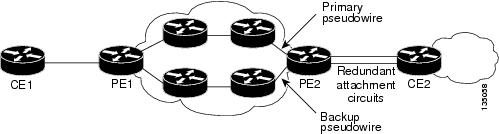
CEoP SPAs support the L2VPN Pseudowire Redundancy feature, which provides backup service for the ATM and CEM pseudowires. Configuring a Pseudowire Redundancy is an optional task. The L2VPN Pseudowire Redundancy feature enables the network to detect a failure and reroute the Layer 2 (L2) service to another endpoint that can continue to provide the service. This feature provides the ability to recover from a failure of either the remote PE router or the link between the PE and CE routers.
Configure pseudowire redundancy by configuring two pseudowires for an ATM interface, a primary pseudowire and a backup (standby) pseudowire. If the primary pseudowire fails, the router uses the backup pseudowire in its place. When the primary pseudowire becomes operational again, the backup pseudowire is stopped and the router resumes the use of the primary pseudowire.
Figure 29-1 shows an example of pseudowire redundancy.
Figure 29-1 Pseudowire Redundancy
The following is a summary of the steps to configure pseudowire redundancy on the SPA-2CHT3-CE-ATM.
Note
SUMMARY STEPS
1.
2.
3.
4.
5.
6.
7.
8.
DETAILED STEPS
Configuring the 2-Port Channelized T3/E3 ATM CEoP SPA for the T3 Mode and the E3 Mode
This section describes how to configure the 2-Port Channelized T3/E3 ATM CEoP SPA. This SPA can be configured to operate in the ATM mode and the CEM mode. The router creates a logical interface to represent the mode that the SPA port is configured to run in. An ATM interface or a CEM interface is created for each T3 port that is configured for the ATM mode or the CEM mode. The interface has the format atm slot/subslot/port or cem slot/subslot/port, where slot/subslot identifies the SPA slot and subslot, and port identifies the port. The same port can be configured either in the CEM mode or in the ATM mode.
The following sections provide instructions for configuring the 2-Port Channelized T3/E3 ATM CEoP SPA:
•
•
Note
Configuring a SPA Port for the T3 Mode
To configure a SPA port for the T3 mode, perform the following steps:
SUMMARY STEPS
1.
2.
3.
4.
5.
6.
7.
DETAILED STEPS
To configure a SPA port for the E3 mode, perform the following steps:
Note
SUMMARY STEPS
1.
2.
3.
4.
5.
6.
DETAILED STEPS
Configuring the T3/E3 SPA Port for the Clear-Channel ATM Mode
To configure a T3/E3 SPA port for the clear-channel ATM mode, perform the following steps:
SUMMARY STEPS
1.
2.
3.
4.
5.
6.
7.
DETAILED STEPS
Step 1
Router(config)# controller {t3} slot/subslot/port
Selects the T3 controller for the port you are configuring, where slot/subslot identifies the SPA location and port identifies the port.
Step 2
Router(config-controller)# atm
Configures the port (interface) for the clear-channel ATM. The router creates an ATM interface whose format is atm /slot/subslot/port, where slot/subslot identifies the SPA slot and subslot, and port identifies the SPA port.
Step 3
Router(config-controller)# exit
Returns to the global configuration mode.
Step 4
Router(config)# interface atm 0/1/2.10 point-to-point
Selects the ATM interface for the SPA port mentioned in Step 1.
Step 5
Router(config-if)# pvc vpi/vci
Configures a PVC for the interface and assigns the PVC a VPI and VCI. Do not specify 0 for both the VPI and VCI. See the "Configuring a Pseudowire for an ATM Connection" section for details about this command.
Step 6
Router(config-if)# xconnect peer-router-id vcid {encapsulation mpls | pseudowire-class name}
Configures a pseudowire to carry data from the clear-channel ATM interface over the MPLS network. See the "Configuring a Pseudowire for an ATM Connection" section for details about this command.
Step 7
Router(config-if)# end
Exits the interface configuration (config-if) mode.
Configuring CEM
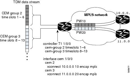
This section provides information about how to configure CEM on the SPA-1CHOC3-CE-ATM, SPA-2CHT3-CE-ATM, and SPA-24CHT1-CE-ATM. The CEM provides a bridge between a time-division multiplexing (TDM) network and a packet network, such as Multiprotocol Label Switching (MPLS). The router encapsulates the TDM data in the MPLS packets and sends the data over a CEM pseudowire to the remote provider edge (PE) router. Thus, functions as a physical communication link across the packet network.
Prerequisites
Prior to configuring CEM on the SPA-1CHOC3-CE-ATM port, SPA-2CHT3-CE-ATM port, and SPA-24CHT1-CE-ATM port, perform the following steps:
1.
2.
Figure 29-2 shows the following sample configurations for the SPA-1CHOC3-CE-ATM, SPA-2CHT3-CE-ATM, and SPA-24CHT1-CE-ATM:
•
•
•
–
–
Figure 29-2 TDM Time Slots-to-Pseudowire Mappings
Table 29-1 lists the number of CEM groups you can configure for each CEM SPA.
Configuration Guidelines and Restrictions
Not all combinations of payload size and dejitter buffer size are supported. Payload size, or dejitter configurations are rejected at the CLI level in the CEM circuit mode on the SPA, if they are not compatible. Incompatible parameter modifications (if any), will be rejected, and the configuration will fall back to the old dejitter and payload parameters if the parameters are being applied through the CEM class template.
Configuring a CEM Group
To configure a CEM group to represent a CEM circuit on a SPA port, perform the following steps:
Note
•
SUMMARY STEPS
1.
2.
or
cem-group group-number timeslots list-of-timesolts3.
Step 1
Selects the controller for the port that is being configured:
•
•
Step 2
Router(config-controller)# [no] cem-group group-number {unframed | timeslots timeslot}Example:Router(config)# controller t1 3/2/0 Router(config-controller)# cem-group 1 unframed Router(config)# controller t1 3/2/1 Router(config-controller)# cem-group 1 timeslots 1,3,5-11 Router(config-controller)# cem-group 2 timeslots 12-24 Router(config)# controller t3 3/2/0Router(config-controller)# t1 1 cem-group 1 timeslots 1Router(config)# controller t3 3/2/1Router(config-controller)# e1 1 cem-group 1 unframedCreates a CEM circuit (group) from one or more time slots of the line connected to this port. To delete the CEM circuit and release the time slots, use the no cem-group group-number command.
•
–
–
–
•
•
Note
Step 3
Exits the controller configuration mode.
DETAILED STEPS
Configuring a CEM Class (Optional)
To assign CEM parameters to one or more CEM interfaces, create a CEM class (template) that defines the parameters, and then apply the class to the interfaces.
CEM class parameters can be configured directly on the CEM circuit. The inheritance is as follows:
•
•
•
If the same parameter is configured on the CEM interface and the CEM circuit, the value on the CEM circuit takes precedence.
To configure a CEM class, perform the following steps:
SUMMARY STEPS
1.
2.
3.
DETAILED STEPS
Step 1
Router# configure terminal
Enters the global configuration mode.
Step 2
Router(config)# class cem name
Creates a CEM class to configure the parameters in a template and apply the parameters at the CEM interface level.
•
Step 3
Router(config-cem-class)# command
Configures the CEM parameters by issuing the appropriate commands. See the "Configuring CEM Parameters" section for information about the commands.
In the following example, a CEM class (TDM-Class-A) is configured to set the payload size and dejitter buffer parameters:
class cem TDM-Class-Apayload-size 512dejitter-buffer 80exitIn the following example, the CEM parameter settings from TDM-Class-A are applied to CEM interface 0/1/0. Any CEM circuits created under this interface inherit these parameter settings.
int cem 0/1/0class int TDM-Class-Acem 6xconnect 10.10.10.10 2 encap mplsexitConfiguring a CEM Pseudowire
To configure a pseudowire to transport a CEM circuit across the MPLS network, perform the following steps:
SUMMARY STEPS
1.
2.
3.
4.
5.
DETAILED STEPS
Step 1
Router(config)# interface cem slot/subslot/port
Selects the CEM interface in which the CEM circuit (group) is located, where slot/subslot is the SIP slot and SPA subslot, and port is the SPA port in which the interface exists.
Step 2
Router(config-if)# cem group-number
Selects the CEM circuit (group) to configure a pseudowire.
Step 3
Router(config-if-cem)# command
(Optional) Defines the operating characteristics for the CEM circuit. For command details, see the "Configuring CEM Parameters" section.
Step 4
Router(config-if)# xconnect peer-router-id vcid {encapsulation mpls | pw-class name}
Configures a pseudowire to transport TDM data from the CEM circuit across the MPLS network.
•
•
•
•
Note
Step 5
Router(config-if)# exit
Exits interface configuration mode.
Example
The following sample configuration shows a T1 port on which two CEM circuits (groups) are configured. Each CEM circuit carries data from the time slots of the TDM circuit attached to the port.
The two xconnect commands create pseudowires to carry the TDM data across the MPLS network. Pseudowire 2 carries the data from time slots 1, 2, 3, 4, 9, and 10 to the remote PE router at 10.10.10.10. Pseudowire 5 carries the data from time slots 5, 6, 7, 8, and 11 to the remote PE router at 10.10.10.11.
controller SONET 0/1/0description This is SONET controllerframing sonetclock source internalloopback network!sts-1 1mode vt-15vtg 1 t1 1 description T1 line to 3rd floor PBXvtg 1 t1 1 clock source Recovered 6vtg 1 t1 1 cem-group 6 timeslots 1-4,9,10vtg 1 t1 1 cem-group 7 timeslots 5-8,11!sts-1 2mode vt-15!sts-1 3mode vt-15int cem0/1/0cem 6xconnect 10.10.10.10 2 encap mplscem 7xconnect 10.10.10.11 5 encap mplsConfiguring TDM Local Switching
TDM Local Switching allows switching of Layer 2 data between two CEM interfaces on the same router. The two CEM groups can be on the same physical interface or different physical interfaces; they can be on the same SPA, the same line card, or different line cards.
Consider the following guidelines before configuring CEM Phase 2 TDM Local Switching:
•
•
•
•
•
•
•
To configure the CEoPS Phase 2 TDM Local Switching, perform the following steps:
SUMMARY STEPS
1.
2.
DETAILED STEPS
Verifying Switching Connections
Use the show connection, show connection all, show connection id conn id, and show connection conn name commands to verify the current switching connections.
Local Switching Redundancy
Local Switching Redundancy provides a backup attachment circuit (AC) when the primary attachment circuit fails. All the ACs must be on the same Cisco ASR 1000 Series Aggregation Services Router.
The following combinations of CEM ACs are supported:
•
•
Guidelines for Local Switching Redundancy
Local Switching Redundancy guidelines are as follows:
•
•
•
•
•
•
•
Configuring a Backup Switched Connection
To configure a backup switched connection, when the primary connection fails, perform the following procedure:
SUMMARY STEPS
1.
2.
3.
DETAILED STEPS
Verifying Backup and Primary Circuits
Use the show xconnect all command to check the status of the backup and primary circuits.
Configuring Pseudowire Redundancy
The SPA-1CHOC3-CE-ATM, SPA-2CHT3-CE-ATM, and SPA-24CHT1-CE-ATM support the L2VPN Pseudowire Redundancy feature that provides backup service for CEM pseudowires. Configuring a Pseudowire Redundancy is an optional task.The L2VPN Pseudowire Redundancy feature enables the network to detect a failure and reroute the Layer 2 (L2) service to another endpoint that can continue to provide service. This feature provides the ability to recover from a failure of either the remote PE router or the link between the PE router and the CE router.
Configure pseudowire redundancy by configuring two pseudowires for a CEM interface, a primary pseudowire and a backup (standby) pseudowire. If the primary pseudowire goes down, the router uses the backup pseudowire in its place. When the primary pseudowire becomes functional again, the backup pseudowire is brought down and the router resumes the use of the primary pseudowire.
Figure 29-3 shows an example of pseudowire redundancy.
Figure 29-3 Pseudowire Redundancy
To configure pseudowire redundancy on a SPA-1CHOC3-CE-ATM, SPA-2CHT3-CE-ATM, or SPA-24CHT1-CE-ATM perform the following steps.
Note
SUMMARY STEPS
1.
2.
3.
4.
5.
6.
DETAILED STEPS
Example
The following example shows pseudowire redundancy configured for a CEM circuit (group). In the following example, the xconnect command configures a primary pseudowire for CEM group 0. The backup peer command creates a redundant pseudowire for a CEM circuit (group).
int cem0/1/0no ip addresscem 0xconnect 10.10.10.1 1 encap mplsbackup peer 10.10.10.2 200exitConfiguring T1 on a 24-Port Channelized T1/E1 ATM CEoP SPA
When configuring T1 on a 24-Port Channelized T1/E1 ATM CEoP SPA, follow these guidelines:
•
•
•
•
•
To configure T1 on a 24-Port Channelized T1/E1 ATM CEoP SPA, perform the following steps:
SUMMARY STEPS
1.
2.
3.
4.
5.
6.
7.
8.
DETAILED STEPS
Configuring E1 on a 24-Port Channelized T1/E1 ATM CEoP SPA
To configure E1 on a 24-Port Channelized T1/E1 ATM CEoP SPA, perform the following steps:
SUMMARY STEPS
1.
2.
3.
4.
5.
6.
7.
8.
DETAILED STEPS
Configuring a 24-Port Channelized T1/E1 ATM CEoP SPA in the Clear-Channel ATM Mode
To configure a T1/E1 SPA port in the clear-channel ATM mode, perform the following steps:
SUMMARY STEPS
1.
2.
3.
4.
5.
6.
7.
DETAILED STEPS
Step 1
enable
Example:Router> enable
Enables the privileged EXEC mode.
Enter your password, if prompted.
Step 2
configure terminal
Example:Router# configure terminal
Enters the global configuration mode.
Step 3
controller{ t1 | e1 } slot/subslot/port
Example:Router(config)# controller t1 0/0/2
Selects the T1 or E1 controller for the slot, the subslot, or the port on the SPA.
Step 4
atm
Example:Router(config-controller)# atm
Configures the port or the slot for the clear-channel ATM.
Step 5
exit
Example:Router(config-controller)# exit
Returns to the global configuration mode.
Step 6
interface atm slot/subslot/port.subinterface number point-to-point
Example:Router(config)# interface atm 0/1/2.10 point-to-point
Specifies the ATM interface for the SPA port mentioned in Step 1.
Step 7
pvc vpi | vci
Example:Router(config-if)# pvc 10/11
Configures a PVC for the interface and assigns the PVC a VPI or VCI. Do not specify 0 for the VPI or the VCI. See the"Configuring a Pseudowire for an ATM Connection" section for more details.
Step 8
xconnect peer-router-id vcid {encapsulation mpls | pseudowire-class name}
Example:Router(config-if)# xconnect 10.0.0.8 2 encapsulation mpls
Configures a pseudowire to carry data from the clear-channel ATM interface over the MPLS network. See the "Configuring a Pseudowire for an ATM Connection" section for more details.
Step 9
end
Example:Router(config-if)# end
Exits the interface configuration mode.
Examples for Configuring a 24-Port Channelized T1/E1 ATM CEoP SPA in the Clear-Channel ATM Mode
The following example shows how to verify the configuration of the 24-Port channelized T1/E1 CEoP SPA:
Router# show controllers T1 1/1/14T1 1/1/14 is up.Applique type is SPA-24CHT1-CE-ATMCablelength is short 133No alarms detected.alarm-trigger is not setSoaking time: 3, Clearance time: 10AIS State:Clear LOS State:Clear LOF State:ClearFraming is ESF, Line Code is B8ZS, Clock Source is Line.Data in current interval (87 seconds elapsed):0 Line Code Violations, 0 Path Code Violations0 Slip Secs, 0 Fr Loss Secs, 0 Line Err Secs, 0 Degraded Mins0 Errored Secs, 0 Bursty Err Secs, 0 Severely Err Secs, 0 Unavail Secs0 Near-end path failures, 0 Far-end path failures, 0 SEF/AIS SecsData in Interval 1:0 Line Code Violations, 0 Path Code Violations0 Slip Secs, 0 Fr Loss Secs, 0 Line Err Secs, 0 Degraded Mins0 Errored Secs, 0 Bursty Err Secs, 0 Severely Err Secs, 0 Unavail Secs0 Near-end path failures, 0 Far-end path failures, 0 SEF/AIS SecsData in Interval 2:0 Line Code Violations, 0 Path Code Violations0 Slip Secs, 0 Fr Loss Secs, 0 Line Err Secs, 0 Degraded Mins0 Errored Secs, 0 Bursty Err Secs, 0 Severely Err Secs, 0 Unavail Secs0 Near-end path failures, 0 Far-end path failures, 0 SEF/AIS SecsData in Interval 3:0 Line Code Violations, 3 Path Code Violations0 Slip Secs, 0 Fr Loss Secs, 0 Line Err Secs, 0 Degraded Mins1 Errored Secs, 0 Bursty Err Secs, 0 Severely Err Secs, 1 Unavail Secs0 Near-end path failures, 0 Far-end path failures, 0 SEF/AIS SecsTotal Data (last 3 15 minute intervals):0 Line Code Violations, 3 Path Code Violations,0 Slip Secs, 0 Fr Loss Secs, 0 Line Err Secs, 0 Degraded Mins,1 Errored Secs, 0 Bursty Err Secs, 0 Severely Err Secs, 1 Unavail Secs0 Near-end path failures, 0 Far-end path failures, 0 SEF/AIS SecsRouter# show ip int brief | inc ATM1/1ATM1/1/6 unassigned YES unset up upATM1/1/14 unassigned YES unset up upATM1/1/14.10 unassigned YES unset up upRouter# show interfaces ATM1/1/14ATM1/1/14 is up, line protocol is upHardware is SPA-24CHT1-CE-ATM, address is 0000.0000.0000 (bia 0000.0000.0000)MTU 4470 bytes, sub MTU 4470, BW 1536 Kbit/sec, DLY 100 usec,reliability 255/255, txload 1/255, rxload 1/255Encapsulation ATM, loopback not setKeepalive not supportedEncapsulation(s): AAL5 AAL02047 maximum active VCs, 1 current VCCsVC Auto Creation Disabled.VC idle disconnect time: 300 seconds1 carrier transitionsLast input never, output never, output hang neverLast clearing of "show interface" counters neverInput queue: 0/375/0/0 (size/max/drops/flushes); Total output drops: 0Queueing strategy: fifoOutput queue: 0/40 (size/max)5 minute input rate 0 bits/sec, 0 packets/sec5 minute output rate 0 bits/sec, 0 packets/sec0 packets input, 0 bytes, 0 no bufferReceived 0 broadcasts (0 IP multicasts)0 runts, 0 giants, 0 throttles0 input errors, 0 CRC, 0 frame, 0 overrun, 0 ignored, 0 abort0 packets output, 0 bytes, 0 underruns0 output errors, 0 collisions, 1 interface resets0 unknown protocol drops0 output buffer failures, 0 output buffers swapped outRouter# show interfaces ATM1/1/14.10ATM1/1/14.10 is up, line protocol is upHardware is SPA-24CHT1-CE-ATM, address is 0000.0000.0000 (bia 0000.0000.0000)MTU 4470 bytes, BW 1536 Kbit/sec, DLY 100 usec,reliability 255/255, txload 1/255, rxload 1/255Encapsulation ATMKeepalive not supported0 packets input, 0 bytes0 packets output, 0 bytes0 OAM cells input, 0 OAM cells outputAAL5 CRC errors : 0AAL5 SAR Timeouts : 0AAL5 Oversized SDUs : 0AAL5 length violation : 0Last clearing of "show interface" counters neverRouter#show interfaces ATM1/1/14.10ATM1/1/14.10 is up, line protocol is upHardware is SPA-24CHT1-CE-ATM, address is 0000.0000.0000 (bia 0000.0000.0000)MTU 4470 bytes, BW 1536 Kbit/sec, DLY 100 usec,reliability 255/255, txload 1/255, rxload 1/255Encapsulation ATMKeepalive not supported0 packets input, 0 bytes0 packets output, 0 bytes0 OAM cells input, 0 OAM cells outputAAL5 CRC errors : 0AAL5 SAR Timeouts : 0AAL5 Oversized SDUs : 0AAL5 length violation : 0Last clearing of "show interface" counters neverRouter# show atm interface ATM1/1/14Interface ATM1/1/14:AAL enabled: AAL5, AAL0, Maximum VCs: 2047, Current VCCs: 1Max. Datagram Size: 4528PLIM Type: DS1, TX clocking: LINECell-payload scrambling: OFF0 input, 0 output, 0 IN fast, 0 OUT fastAvail bw = 1536Config. is ACTIVERouter#Router#show atm interface ATM1/1/14.10Interface ATM1/1/14.10:AAL enabled: AAL5, AAL0, Maximum VCs: 2047, Current VCCs: 1Max. Datagram Size: 4528PLIM Type: DS1, TX clocking: LINECell-payload scrambling: OFF0 input, 0 output, 0 IN fast, 0 OUT fastAvail bw = 1536Config. is ACTIVEThe following example displays the output of the show commands in the E1 mode:
Router# show controllers e1 1/1/14E1 1/1/14 is up.Applique type is SPA-24CHT1-CE-ATMCablelength is UnknownNo alarms detected.alarm-trigger is not setFraming is crc4, Line Code is HDB3, Clock Source is Line.International Bit: 1, National Bits: 11111Data in current interval (599 seconds elapsed):0 Line Code Violations, 0 Path Code Violations0 Slip Secs, 0 Fr Loss Secs, 0 Line Err Secs, 0 Degraded Mins0 Errored Secs, 0 Bursty Err Secs, 0 Severely Err Secs, 0 Unavail Secs0 Near-end path failures, 0 Far-end path failures, 0 SEF/AIS SecsRouter# show interfaces ATM1/1/14ATM1/1/14 is up, line protocol is upHardware is SPA-24CHT1-CE-ATM, address is 0000.0000.0000 (bia 0000.0000.0000)MTU 4470 bytes, sub MTU 4470, BW 1920 Kbit/sec, DLY 100 usec,reliability 255/255, txload 1/255, rxload 1/255Encapsulation ATM, loopback not setKeepalive not supportedEncapsulation(s): AAL5 AAL02047 maximum active VCs, 0 current VCCsVC Auto Creation Disabled.VC idle disconnect time: 300 seconds1 carrier transitionsLast input never, output never, output hang neverLast clearing of "show interface" counters neverInput queue: 0/375/0/0 (size/max/drops/flushes); Total output drops: 0Queueing strategy: fifoOutput queue: 0/40 (size/max)5 minute input rate 0 bits/sec, 0 packets/sec5 minute output rate 0 bits/sec, 0 packets/sec0 packets input, 0 bytes, 0 no bufferReceived 0 broadcasts (0 IP multicasts)0 runts, 0 giants, 0 throttles0 input errors, 0 CRC, 0 frame, 0 overrun, 0 ignored, 0 abort0 packets output, 0 bytes, 0 underruns0 output errors, 0 collisions, 1 interface resets0 unknown protocol drops0 output buffer failures, 0 output buffers swapped outRouter# show interfaces ATM1/1/14*May 24 00:41:57.886: %SYS-5-CONFIG_I: Configured from console by console.10ATM1/1/14.10 is up, line protocol is upHardware is SPA-24CHT1-CE-ATM, address is 0000.0000.0000 (bia 0000.0000.0000)MTU 4470 bytes, BW 1920 Kbit/sec, DLY 100 usec,reliability 255/255, txload 1/255, rxload 1/255Encapsulation ATMKeepalive not supported0 packets input, 0 bytes0 packets output, 0 bytes0 OAM cells input, 0 OAM cells outputAAL5 CRC errors : 0AAL5 SAR Timeouts : 0AAL5 Oversized SDUs : 0AAL5 length violation : 0Last clearing of "show interface" counters neverRouter# show atm interface ATM1/1/14Interface ATM1/1/14:AAL enabled: AAL5, AAL0, Maximum VCs: 2047, Current VCCs: 1Max. Datagram Size: 4528PLIM Type: E1, TX clocking: LINECell-payload scrambling: OFF0 input, 0 output, 0 IN fast, 0 OUT fastAvail bw = 1920Config. is ACTIVERouter#show atm interface ATM1/1/14.10Interface ATM1/1/14.10:AAL enabled: AAL5, AAL0, Maximum VCs: 2047, Current VCCs: 1Max. Datagram Size: 4528PLIM Type: E1, TX clocking: LINECell-payload scrambling: OFF0 input, 0 output, 0 IN fast, 0 OUT fastAvail bw = 1920Config. is ACTIVERouter# show atm pvcVCD / Peak Av/Min BurstInterface Name VPI VCI Type Encaps SC Kbps Kbps Cells St1/1/14.10 1 10 11 PVC SNAP UBR 1920 UPConfiguring SONET (OC-3)
Use the following guidelines to configure SONET (OC-3) on the1-Port Channelized OC-3 STM1 ATM CEoP SPA:
•
•
•
•
•
Configuring the SONET Controller
To configure the SONET controller, perform the following steps:
SUMMARY STEPS
1.
2.
3.
4.
5.
or
vtg vtg number t1 t1 line number cem-group channel-number timeslots list-of-timeslots6.
DETAILED STEPS
Configuring SDH for AU-4 C-12
To enable an interface under SDH framing with AU-4 mapping after configuring the SONET controller, perform the following steps:
SUMMARY STEPS
1.
2.
3.
4.
5.
6.
or
tug-2 tug-2 number e1 e1-line-number cem-group channel-number timeslots list-of-timeslotsDETAILED STEPS
Configuring SDH for AU-3 C-11
To enable an interface under SDH framing with AU-3 mapping after configuring the SONET controller, perform the following steps:
SUMMARY STEPS
1.
2.
3.
4.
5.
6.
or
tug-2 tug-2 number e1 e1-line-number cem-group channel-number timeslots list-of-timeslotsDETAILED STEPS
Configuring Clocking
This section provides information about how to configure clocking on the SPA-24CHT1-CE-ATM or the SPA-1CHOC3-CE-ATM, and contains the following topics:
•
•
BITS Clock Support—Receive and Distribute—CEM SPA
You can use the BITS Clock Support—Receive and Distribute—CEM SPA feature to select and configure a clock and distribute it across the chassis to be used as the Transmit reference on all SPA ports.
The line card operates in three different modes, depending on the configuration and the configured source state.
•
•
•
Note
Guidelines for Configuring the Network Clock
To configure the network clock, consider the following guidelines:
•
•
•
•
•
Configuring the Network Clock
To configure the network clock for a Cisco ASR 1000 Series Aggregation Services Router, perform the following procedure:
Note
SUMMARY STEPS
1.
2.
3.
4.
5.
6.
7.
8.
9.
DETAILED STEPS
Verifying the Network Clock Configuration
Use the show network-clocks command to verify the output on the RP:
Router# show network-clocksActive source = SONET 0/1/0Active source backplane reference line = Primary Backplane ClockAll Network Clock Configuration---------------------------------Priority Clock Source State Reason1 SONET 0/1/0 ValidCurrent operating mode is RevertiveCurrent OOR Switchover mode is SwitchoverThere are no slots disabled from participating in network clockingConfiguring Clock Recovery
When configuring clock recovery, consider the following guidelines:
Adaptive Clocking
•
•
•
•
•
Differential Clock Recovery
•
•
•
•
To configure clock recovery on a 24-Port Channelized T1/E1 ATM CEoP SPA, a 2-Port Channelized T3/E3 ATM CEoP SPA, or a 1-Port Channelized OC-3 STM1 ATM CEoP SPA, perform the following procedure:
SUMMARY STEPS
1.
2.
3.
4.
5.
DETAILED STEPS
Applying the Recovered Clock to the Controller
To apply the recovered clock to the controller, perform the following steps:
SUMMARY STEPS
1.
2.
3.
4.
DETAILED STEPS
Example for Configuring Clock Recovery
The following example shows how to configure clock recovery:
Configuration on CE1
controller t3 1/0/1cablelength 224t1 1 channel-group 1 timeslots 1-24clock source internal
Note
Configuration on PE1
controller T3 0/3/0clock source linecablelength 224configuration on CE2
controller T3 1/0/1clock source linecablelength 224t1 1 channel-group 1 timeslots 1-24Configuration on PE2
recovered-clock configuration:
recovered-clock 0 3clock recovered 1 adaptive cem 0 1configuration for applying recovered clock to controller:
controller T3 0/3/0cablelength 224t1 1 cem-group 1 timeslots 1-24t1 1 clock source Recovered 1Verifying Clock Recovery
To verify clock recovery, use the show recovered-clock command.
Router# show recovered-clockRecovered clock status for subslot 1/0----------------------------------------Clock Mode Port CEM Status Frequency Offset(ppb)1 ADAPTIVE 0 1 HOLDOVER 0Router# show recovered-clockRecovered clock status for subslot 1/0----------------------------------------Clock Mode Port CEM Status Frequency Offset(ppb)1 ADAPTIVE 0 1 ACQUIRING -694Configuring Out-of-Band Clocking
A TDM network requires a synchronized clock at each end of the connection (source and destination). This means that the source and destination clock signals must be synchronized with each other in order to maintain data integrity on the communication link.
On the other hand, a packet-switched network (PSN) does not use a clocking strategy, which means that the PSN does not provide frequency synchronization between the source and the destination routers. Therefore, to transmit TDM data across a PSN (such as an MPLS network), we need a way to deliver the clocking signal between the source and the destination routers.
Out-of-band clocking provides a way to deliver a clock signal between two SPAs. This allows TDM devices connected to the SPAs to communicate with each other. Dedicated pseudowires (called out-of-band clock channels) carry the timing signal between the sending and the receiving SPAs. When a TDM device sends data to a destination TDM device, the receiving SPA uses the out-of-band clock channel to recover the clock signal that was used to send the data.
By keeping the timing packets separate from data packets, out-of-band clocking delivers an extremely accurate timing signal. This timing accuracy is important for mobile wireless applications and other specialized applications that have very low tolerances for such things as packet delay variation (PDV), jitter, and latency in the network. In-band clocking (where timing information is derived from the data stream) does not provide a clock that is accurate enough for these applications.
To set up out-of-band clock channels, you must configure a master clock interface and a slave clock interface on the SPAs and configure pseudowires to connect the master and slave clocks. Instructions for performing these steps are provided later in this section.
Note
Benefits of Out-Of-Bank Clocking
Out-of-band clocking provides the following benefits:
•
•
•
•
•
•
•
Guidelines for Configuring Out-Of-Band Clocking
The following guidelines apply to out-of-band clocking on CEM SPA:
•
•
•
•
When no network clock is available, the virtual CEM interface goes down and the pseudowire is disabled. This process is reversed when a valid network clock becomes available again. Normal CEM interfaces never go down, even if the associated physical link is down.•
Router Sending Clock (Master Clock)
•
•
•
•
Router Recovering Clock (Slave Clock)
•
•
•
Overview of Configuring Out-of-band Clocking Between Two CEM SPAs
The following section provides a high-level overview of the procedure for configuring out-of-band clocking between two CEM SPAs. Detailed steps are provided in the sections that follow.
Before you begin, determine which CEM SPAs have TDM devices connected to them. You must configure an out-of-band clock channel to deliver the clock signal from each SPA that sends TDM data to every destination SPA that receives the data.
1.
2.
a.
b.
Note
3.
–
–
Note
4.
a.
b.
Creating the Master Clock Interface
To create the master clock interface for out-of-band clocking, perform the following procedure.
SUMMARY STEPS
1.
2.
DETAILED STEPS
Configuring an Out-Of-Band Channel
To configure an out-of-band channel to use the master clock signal, perform the following steps:
SUMMARY STEPS
1.
2.
3.
4.
DETAILED STEPS
Step 1
Router(config)# interface virtual-cem slot/subslot/port
Selects the virtual CEM interface for the master clock and enters interface configuration mode. The interface has the same slot and subslot as the SPA from which the master clock was recovered (Step 1 in the preceding task), and the port number is always 24.
Step 2
Router(config-if)# cem circuit-id
Creates a CEM attachment circuit for the master clock signal. Valid values for circuit-id are 0 to 63.
Note
Step 3
Router(config-if-cem)# xconnect peer-router-id vcid encapsulation mpls
Configures an out-of-band channel (pseudowire) to carry the master clock signal.
•
•
•
Note
Step 4
Router(config-if-cem-xconn)# end
Exits CEM interface configuration mode and returns you to privileged EXEC mode.
Note
Configuring the Slave Clock Interface
To configure the slave clock interface and out-of-band channel to use for out-of-band clocking, perform the following steps.
Note
SUMMARY STEPS
1.
2.
3.
4.
5.
6.
7.
DETAILED STEPS
Step 1
Router(config)# recovered-clock slot/subslot
Specifies the slot and subslot of the CEM SPA from which the master clock is recovered.
Step 2
Router(config-clock)# clock slave
Creates a virtual CEM interface to represent the clock slave for out-of-band clocking.
Step 3
Router(config)# exit
Exits from the Clock configuration mode and enters the global configuration mode.
Step 4
Router(config)# int virtual-cem slot/subslot/port
Enters configuration mode for the virtual CEM interface that represents the clock slave.
•
•
Step 5
Router(config-if)# cem circuit-id
Creates a CEM attachment circuit for the clock slave. The circuit-id value can be:
•
•
Note
Step 6
Router(config-if-cem)# xconnect peer-router-id vcid encapsulation mpls
Configures an out-of-band channel (pseudowire) to carry the clock signal.
•
•
•
Note
Step 7
Router(config-if-cem-xconn)# end
Exits CEM interface configuration mode and returns you to privileged EXEC mode.
Verifying Out-of-Band Clocking
This section lists the show commands that you can use to verify the out-of-band clocking configuration.
•
Router# show ip int brief. . .Virtual-cem0/1/24 unassigned YES unset up up. . .•
Router# show cem circuitCEM Int. ID Line Admin Circuit AC--------------------------------------------------------------CEM0/1/0 1 DOWN DOWN Active --/--Virtual-cem0/1/24 DOWN UP Active UP•
Router# show cem interface virtual-cem 0/1/24(Virtual-cem0/1/24) State: CONFIG COMPLETEVirtual CEM Slave Clock InterfaceSlot 0, Slot Unit 88, VC -1Total cem circuits: 1Cem circuits up : 1Cem circuits down : 0•
Router# show run int virtual-cem 0/1/24Building configuration...Current configuration : 117 bytes!interface Virtual-cem0/1/24no ip addresscem 1xconnect 20.0.0.1 300 encapsulation mpls!end•
Router# show run | begin recoveredrecovered-clock 0 1clock master•
Router# show recovered-clockRecovered clock status for subslot 0/1----------------------------------------Clock Mode Port CEM Status Frequency Offset(ppb)ENHANCED PRIMARY 0 HOLDOVER 0Removing the Out-of-Band Clocking Configuration
Use the following commands to delete the various components used for out-of-band clocking:
•
Router# conf tEnter configuration commands, one per line. End with CNTL/Z.Router(config)# int virtual-cem 0/1/24Router(config-if)# no cem 1Router(config-if)# end•
Router# conf tEnter configuration commands, one per line. End with CNTL/Z.Router(config)# recovered-clock 0 1Router(config-clock)# no clock masterRouter(config-clock)# endRouter#In the following example, the no clock slave command deletes the slave clock interface for the recovered clock (which is 0/1):
Router# config tEnter configuration commands, one per line. End with CNTL/Z.Router(config)# recovered-clock 0 1Router(config-clock)# no clock slaveRouter(config-clock)# endRouter#Example: Out-of-Band Clocking Configuration
This section provides an example of how to configure out-of-band clocking between two CEM SPAs. It is divided into several different configuration sections.
Configuring the Master Clock Interface
The following example shows how to configure a CEM SPA as a master clock and verify the configuration:
Router# config tEnter configuration commands, one per line. End with CNTL/Z.Router (config)# recovered-clock ?<0-14> Slot numberRouter (config)# recovered-clock 0 1Router(config-clock)# clock ?master Configure clock master on the cardrecovered Configure recovered clock on the cardreference Configure reference clock on the cardslave Configure clock slave on the cardRouter(config-clock)# clock masterRouter(config-clock)# endRouter# show run | begin recoveredrecovered-clock 0 1clock masterConfiguring the Slave Clock Interface
The following example shows how to configure a CEM SPA as a slave clock and verify the configuration:
Router# config tEnter configuration commands, one per line. End with CNTL/Z.Router(config)# recovered-clock 0 1Router(config-clock)# clock slaveRouter(config-clock)# endRouter#Router# show run | begin recovered-clockrecovered-clock 0 1clock slaveVerifying the Virtual CEM Interface Configuration
The router creates a virtual CEM interface when you configure either the master or slave clock interface. You can view the interface using the show ip interface brief command:
Router# show ip int br...Virtual-cem0/1/24 unassigned YES unset up up...Router# sh run int Virtual-cem 0/1/24Building configuration...Current configuration : 50 bytes!interface Virtual-cem0/1/24no ip addressendExample: Configuring CEM Circuits for Out-of-Band Clocking
This section provides an example of how to configure CEM circuits and pseudowires for out-of-band clocking. The sample configuration shows the circuits and pseudowires configured on a CEM SPA in PE1, which sends TDM data to another CEM SPA in PE2.
You configure CEM circuits for the master and slave clocks under the virtual CEM interface that represents the recovered clock that is being used for out-of-band clocking. This differs from normal CEM circuits, which are configured under the SPA controller through the cem-group command.
Issuing the xconnect command under the master and slave CEM circuits, configures an out-of-band clock channel to send the clock signal from the sending SPA to the receiving SPA. Note that normal CEM pseudowires are configured under the SPA controller interface.
Out-of-Band Clocking (PE1)
PE1# config tPE1(config)# int virtual-cem 0/1/24PE1(config-if)# cem 1PE1(config-if-cem)# xconnect 20.0.0.1 200 encap mplsPE1(cfg-if-cem-xconn)# endPE1# show run int Virtual-CEM 0/1/24Building configuration...Current configuration : 117 bytes!interface Virtual-cem0/1/24no ip addresscem 1xconnect 20.0.0.1 200 encapsulation mpls!endOut-of-Band Clocking (PE2)
PE2# conf tPE2(config)# int virtual-cem 0/1/24PE2(config-if)# cem 1PE2(config-if-cem)# xconnect 10.0.0.1 200 encap mplsPE2(cfg-if-cem-xconn)# endPE2# show run int Virtual-CEM 0/1/24Building configuration...Current configuration : 117 bytes!interface Virtual-cem0/1/24no ip addresscem 1xconnect 10.0.0.1 200 encapsulation mpls!endConfiguring CEM Parameters
The following sections describe the parameters you can configure for CEM circuits.
Note
Configuring Payload Size (Optional)
To specify the number of bytes encapsulated into a single IP packet, use the pay-load size command. The size argument specifies the number of bytes in the payload of each packet. The range is from 32 to 1313 bytes.
Default payload sizes for an unstructured CEM channel are as follows:
•
•
•
•
Default payload sizes for a structured CEM channel depend on the number of time slots that constitute the channel. Payload size (L in bytes), number of time slots (N), and packetization delay (D in milliseconds) have the following relationship: L = 8*N*D. The default payload size is selected in such a way that the packetization delay is always 1 millisecond. For example, a structured CEM channel of 16xDS0 has a default payload size of 128 bytes.
The payload size must be an integer of the multiple of the number of time slots for structured CEM channels.
Setting the Dejitter Buffer Size
To specify the size of the dejitter buffer used to compensate for the network filter, use the dejitter-buffer size command. The configured dejitter buffer size is converted from milliseconds to packets and rounded up to the next integral number of packets. Use the size argument to specify the size of the buffer, in milliseconds. The range is from 1 to 500 ms; the default is 5 ms.
Setting the Idle Pattern (Optional)
To specify the idle pattern, use the [no] idle-pattern pattern1 command. The payload of each lost CESoPSN data packet must be replaced with the equivalent amount of the replacement data. The range for pattern is from 0x0 to 0xFF; the default idle pattern is 0xFF.
Enabling the Dummy Mode
The dummy mode enables a bit pattern for filling in for lost or corrupted frames. To enable dummy mode, use the dummy-mode [last-frame | user-defined] command. The default is last-frame. The following is an example:
Router(config-cem)# dummy-mode last-frameSetting the Dummy Pattern
If dummy mode is set to user defined, you must use the dummy-pattern pattern command to configure the dummy pattern. The range for pattern is from 0x0 to 0xFF. The default dummy pattern is 0xFF. The following is an example:
Router(config-cem)# dummy-pattern 0x55Shutting Down a CEM Channel
To shut down a CEM channel, use the shutdown command in CEM configuration mode. The shutdown command is supported only under CEM mode and not under the CEM class.
Configuring Layer 3 QoS on CEoP SPAs
The SIPs and 2-Port Channelized T3/E3 ATM CEoP SPA support many QoS features that use modular QoS CLI (MQC) configuration.
Restrictions
The following restriction exists when configuring a Layer 3 QoS on the CEoP SPA:
•
Supported Interface
The following interfaces are supported for the 2-Port Channelized T3/E3 ATM CEoP SPA:
•
•
•
•
Configuring the QoS Features on the 2-Port Channelized T3/E3 ATM CEoP SPA
To configure the QoS features on the 2-Port Channelized T3/E3 ATM CEoP SPA, perform the following steps:
SUMMARY STEPS
1.
2.
3.
4.
5.
6.
7.
8.
DETAILED STEPS
Sample Configuration
The following example shows how to configure a Layer 3 QOS on the CEoP SPA:
Router# configure terminalRouter(config)# interface atm 3/0/0.1 point-to-pointRouter(config-if)# ip address 24.0.0.1 255.255.255.0Router(config-if)# pvc 1/40Router(config-if-atm-vc)# service-policy in omni_flat_ingress10Router(config-if-atm-vc)# service-policy out flat_brr10Router(config-if-atm-vc)# endVerifying the Configuration
The following example shows how to verify the configuration:
Router# show policy-map interface cem3/0/0.1/1/1CEM3/0/0.1/1/1: VC 1/40 -Service-policy input: omni_flat_ingress10Counters last updated 00:00:03 agoClass-map: prec4 (match-all)0 packets, 0 bytes30 second offered rate 0000 bps, drop rate 0000 bpsMatch: precedence 4 police:cir 52500 bps, bc 4470 bytesconformed 0 packets, 0 bytes; actions:transmitexceeded 0 packets, 0 bytes; actions:dropconformed 0000 bps, exceeded 0000 bpsClass-map: prec5 (match-all)0 packets, 0 bytes30 second offered rate 0000 bps, drop rate 0000 bpsMatch: precedence 5police:cir 54000 bps, bc 4470 bytesconformed 0 packets, 0 bytes; actions:transmitexceeded 0 packets, 0 bytes; actions:dropconformed 0000 bps, exceeded 0000 bpsClass-map: prec6 (match-all)391 packets, 29584 bytes30 second offered rate 0000 bps, drop rate 0000 bpsMatch: precedence 6police:cir 56000 bps, bc 4470 bytesconformed 391 packets, 29584 bytes; actions:transmitexceeded 0 packets, 0 bytes; actions:dropconformed 0000 bps, exceeded 0000 bpsClass-map: class-default (match-any)255775 packets, 194214265 bytes30 second offered rate 1325000 bps, drop rate 1275000 bpsMatch: anypolice:cir 51000 bps, bc 4470 bytesconformed 30423 packets, 7439395 bytes; actions:transmitexceeded 225352 packets, 186774870 bytes; actions:dropconformed 51000 bps, exceeded 1275000 bpsService-policy output: omni_flat10Counters last updated 00:00:03 agoqueue stats for all priority classes:Queueingpriority level 1queue limit 12 packets(queue depth/total drops/no-buffer drops) 0/0/0(pkts output/bytes output) 43602/7460616queue stats for all priority classes:Queueingpriority level 2queue limit 14 packets(queue depth/total drops/no-buffer drops) 0/0/0(pkts output/bytes output) 0/0Class-map: prec4 (match-all)0 packets, 0 bytes30 second offered rate 0000 bps, drop rate 0000 bpsMatch: precedence 4Queueingqueue limit 13 packets(queue depth/total drops/no-buffer drops) 0/0/0(pkts output/bytes output) 0/0bandwidth 52 kbpsConfiguring AIS and RAI Alarm Forwarding in the CESoPSN Mode on the CEoP SPAs
This feature allows grooming of traffic from several different cell-site fractional T1/E1s via CEM, through an MPLS cloud, on to a single aggregate T1/E1 going to the BSC.
This feature provides the following functionalities:
•
•
•
Restrictions
The following restrictions are applicable while configuring AIS and RAI alarm forwarding:
•
•
Configuring AIS and RAI Alarm Forwarding for T1 on the CEoP SPA
To enable AIS and RAI alarm forwarding on the SPA-24CHT1-CE-ATM and the SPA-2CHT3-CE-ATM for T1 mode, perform the following procedure:
SUMMARY STEPS
1.
2.
3.
or
controller t3 slot/subslot/port4.
or
t1 1-28 forward-alarm ais/raiDETAILED STEPS
Configuring AIS and RAI Alarm Forwarding for E1 on the CEoP SPA
To enable AIS and RAI forwarding on the SPA-24CHT1-CE-ATM and the SPA-2CHT3-CE-ATM for E1 mode, perform the following procedure:
SUMMARY STEPS
1.
2.
3.
or
controller t3 slot/subslot/port4.
or
e1 1-21 forward-alarm ais/raiDETAILED STEPS
Configuring the SONET Mode
To enable AIS/RAI forwarding on the CEoP SPAs for SONET mode, perform the following steps:
SUMMARY STEPS
1.
2.
3.
DETAILED STEPS
Configuring the SDH AU-4 Mode
To enable AIS or RAI forwarding on the CEoP SPAs for SDH AU-4 mode, perform the following steps:
SUMMARY STEPS
1.
2.
3.
4.
5.
6.
DETAILED STEPS
Configuring the SDH AU-3 Mode
To enable AIS or RAI forwarding on the CEoP SPAs for SDH AU-3 mode, perform the following steps:
SUMMARY STEPS
1.
2.
3.
4.
5.
6.
DETAILED STEPS
Restrictions
The following restrictions apply while configuring AIS or RAI alarm forwarding:
•
•
Verifying the Interface Configuration
The show cem circuit command shows information about the circuit state, administrative state, the CEM ID of the circuit, and the interface on which it is configured. If xconnect is configured under the circuit, the command output also includes information about the attached circuit.
Router# show cem circuit ?<0-504> CEM IDdetail Detailed information of cem ckt(s)interface CEM Interfacesummary Display summary of CEM ckts| Output modifiersRouter# show cem circuitCEM Int. ID Line Admin Circuit AC--------------------------------------------------------------CEM0/1/0 1 UP UP ACTIVE --/--CEM0/1/0 2 UP UP ACTIVE --/--CEM0/1/0 3 UP UP ACTIVE --/--CEM0/1/0 4 UP UP ACTIVE --/--CEM0/1/0 5 UP UP ACTIVE --/--The show cem circuit 0-504 command displays the detailed information about that particular circuit.
Router# show cem circuit 1CEM0/1/0, ID: 1, Line State: UP, Admin State: UP, Ckt State: ACTIVEIdle Pattern: 0xFF, Idle cas: 0x8, Dummy Pattern: 0xFFDejitter: 5, Payload Size: 40Framing: Framed, (DS0 channels: 1-5)Channel speed: 56CEM Defects SetExcessive Pkt Loss RatePacket LossSignalling: No CASIngress Pkts: 25929 Dropped: 0Egress Pkts: 0 Dropped: 0CEM Counter DetailsInput Errors: 0 Output Errors: 0Pkts Missing: 25927 Pkts Reordered: 0Misorder Drops: 0 JitterBuf Underrun: 1Error Sec: 26 Severly Errored Sec: 26Unavailable Sec: 5 Failure Counts: 1Pkts Malformed: 0The show cem circuit summary command displays the number of circuits which are up or down per interface basis.
Router# show cem circuit summaryCEM Int. Total Active Inactive--------------------------------------CEM0/1/0 5 5 0The show running configuration command shows detail on each CEM group:
Router# show running configurationBuilding configuration...Current configuration : 1720 bytes!! Last configuration change at 17:22:39 UTC Wed Jan 5 2011!version 15.1service timestamps debug datetime msecservice timestamps log datetime msecno platform punt-keepalive disable-kernel-core!hostname Router!boot-start-markerboot-end-marker!!vrf definition Mgmt-intf!address-family ipv4exit-address-family!address-family ipv6exit-address-family!!no aaa new-modelip source-route!!multilink bundle-name authenticated!redundancymode none!!!controller SONET 0/1/0framing sonetclock source line!sts-1 1mode vt-15vtg 1 t1 1 cem-group 1 timeslots 1vtg 2 t1 1 cem-group 6 timeslots 1-24vtg 3 t1 2 cem-group 7 timeslots 1-24!sts-1 2mode vt-15!sts-1 3mode vt-15!!recovered-clock 0 1clock master!ip tftp source-interface GigabitEthernet0!class cem cemqospayload-size 256dejitter-buffer 20dummy-mode last-frame!!interface GigabitEthernet0/0/0no ip addressnegotiation auto!interface GigabitEthernet0/0/1no ip addressnegotiation auto!interface GigabitEthernet0/0/2no ip addressnegotiation auto!interface GigabitEthernet0/0/3no ip addressnegotiation auto!interface GigabitEthernet0vrf forwarding Mgmt-intfno ip addressnegotiation auto!interface CEM0/1/0no ip addresscem 1cem class cemqos!cem 6xconnect 10.10.10.10 3 encapsulation mpls!cem 7xconnect 10.10.10.11 2 encapsulation mpls!!interface Virtual-cem0/1/24no ip address!ip forward-protocol nd!no ip http serverno ip http secure-server!logging esm config!!!control-plane!!!!!line con 0stopbits 1line vty 0 4login!exception data-corruption buffer truncateendRouter# show int cem 0/1/0CEM0/1/0 is up, line protocol is upHardware is Circuit Emulation InterfaceMTU 1500 bytes, BW 155520 Kbit/sec, DLY 0 usec,reliability 255/255, txload 1/255, rxload 1/255Encapsulation CEM, loopback not setKeepalive not supportedLast input never, output never, output hang neverLast clearing of "show interface" counters neverInput queue: 0/375/0/0 (size/max/drops/flushes); Total output drops: 0Queueing strategy: fifoOutput queue: 0/0 (size/max)5 minute input rate 64000 bits/sec, 250 packets/sec5 minute output rate 0 bits/sec, 0 packets/sec1779066 packets input, 56930112 bytes, 0 no bufferReceived 0 broadcasts (0 IP multicasts)0 runts, 0 giants, 0 throttles0 input errors, 0 CRC, 0 frame, 0 overrun, 0 ignored, 0 abort0 packets output, 0 bytes, 0 underruns0 output errors, 0 collisions, 0 interface resets0 unknown protocol drops0 output buffer failures, 0 output buffers swapped outRouter# show class cem cemqosClass: cemqos , Dummy mode: last-frameDejitter: 20, Payload Size: 256Router# show class cem detailClass: cemqos , Dummy mode: last-frameDejitter: 20, Payload Size: 256Circuits inheriting this Class:CEM0/1/0: Circuit 1Interfaces inheriting this Class:None