The Cisco Unified Computing System™ (Cisco UCS™) is a set of data center components that includes blade and rack servers, adapters, fabric interconnects, and extenders unified under a common embedded management system. This model results in far fewer system components and much better manageability, operation efficiency, and flexibility than comparable data center platforms.
Main Differentiating Technologies
The main differentiating technologies described here are what make Cisco UCS unique and give it advantages over competing offerings. The technologies presented here are high level, and the discussions do not include the technologies (such as Fibre Channel over Ethernet [FCoE]) that support these high-level elements.
Unified Fabric
Unified fabric can dramatically reduce the number of network adapters, blade-server switches, cables, and management touch points by passing all network traffic to parent fabric interconnects, where it can be prioritized, processed, and managed centrally. This approach improves performance, agility, and efficiency and dramatically reduces the number of devices that need to be powered, cooled, secured, and managed.
Cisco Extended Memory Technology
Significantly enhancing the available memory capacity of some Cisco UCS servers, Cisco® Extended Memory Technology helps increase performance for demanding virtualization and large-data-set workloads. Data centers can now deploy very high virtual machine densities on individual servers as well as provide resident memory capacity for data bases that need only two processors but can dramatically benefit from more memory. The high-memory dual in-line memory module (DIMM) slot count also lets users more cost-effectively scale this capacity using smaller, less costly DIMMs.
Virtual Machine Fabric Extender Technology
With Virtual Machine Fabric Extender Technology (VM-FEX), virtual machines have virtual links that allow them to be managed in the same way as physical links. Virtual links can be centrally configured and managed without the complexity of traditional systems that interpose multiple switching layers in virtualized environments. I/O configurations and network profiles move along with virtual machines, helping increase security and efficiency while reducing complexity. VM-FEX helps improve performance and reduce network interface card (NIC) infrastructure.
Dynamic Provisioning with Service Profiles
Cisco UCS Manager delivers service profiles, which contain abstracted server-state information, creating an environment in which everything unique about a server is stored in the fabric, and the physical server is simply another resource to be assigned. Cisco UCS Manager implements role- and policy-based management focused on service profiles and templates. These mechanisms fully provision one or many servers and their network connectivity in minutes, rather than hours or days.
Cisco UCS Manager
Cisco UCS Manager is a centralized management application that is embedded on the fabric switch. Cisco UCS Manager controls all Cisco UCS elements within a single redundant management domain. These elements include all aspects of system configuration and operation, eliminating the need to use multiple, separate element managers for each system component. Massive reduction in the number of management modules and consoles and in the proliferation of agents resident on all the hardware (which must be separately managed and updated) are important deliverables of Cisco UCS. Cisco UCS Manager, using role-based access and visibility, helps enable cross-function communication efficiency, promoting collaboration between data center roles for increased productivity.
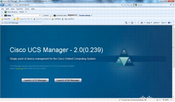
Cisco UCS Manager can be accessed through an intuitive GUI, a command-line interface (CLI), or the comprehensive open XML API. It manages the physical assets of the server and storage and LAN connectivity, and it is designed to simplify the management of virtual network connections through integration with several major hypervisor vendors. It provides IT departments with the flexibility to allow people to manage the system as a whole, or to assign specific management functions to individuals based on their roles as managers of server, storage, or network hardware assets. It simplifies operations by automatically discovering all the components available on the system and enabling a stateless model for resource use.
The elements managed by Cisco UCS Manager include:
• BIOS firmware and settings, including server universal user ID (UUID) and boot order
• Converged network adapter (can) firmware and settings, including MAC and worldwide name (WWN) addresses and SAN boot settings
• Virtual port groups used by virtual machines, using Cisco Data Center VM-FEX technology
• Interconnect configuration, including uplink and downlink definitions, MAC and WWN address pinning, VLANs, VSANs, quality of service (QoS), bandwidth allocations, Cisco Data Center VM-FEX settings, and EtherChannels to upstream LAN switches
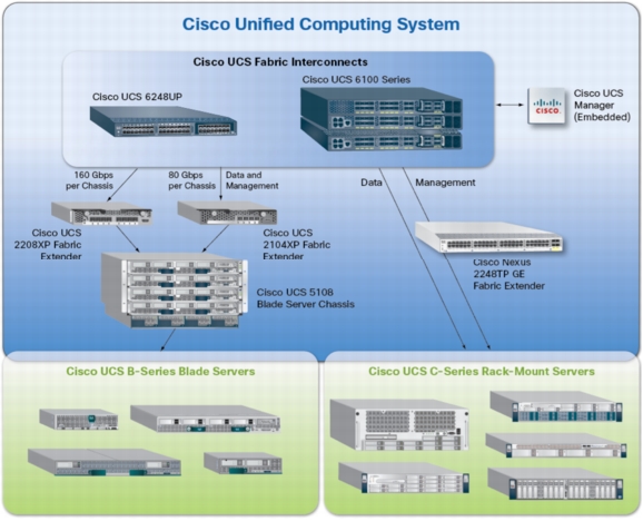
Cisco Unified Computing System Components
Figure 1 shows the Cisco UCS components.
Figure 1. Cisco UCS Components
Cisco UCS is designed from the start to be programmable and self-integrating. A server's entire hardware stack, ranging from server firmware and settings to network profiles, is configured through model-based management. With Cisco virtual interface cards (VICs), even the number and type of I/O interfaces is programmed dynamically, making every server ready to power any workload at any time.
With model-based management, administrators manipulate a model of a desired system configuration and associate a model's service profile with hardware resources, and the system configures itself to match the model. This automation speeds provisioning and workload migration with accurate and rapid scalability. The result is increased IT staff productivity, improved compliance, and reduced risk of failures due to inconsistent configurations.
Cisco Fabric Extender Technology (FEX Technology) reduces the number of system components that need to be purchased, configured, managed, and maintained by condensing three network layers into one. It eliminates both blade server and hypervisor-based switches by connecting fabric interconnect ports directly to individual blade servers and virtual machines. Virtual networks are now managed exactly as physical networks are, but with massive scalability. This approach represents a radical simplification compared to traditional systems, reducing capital and operating costs while increasing business agility, simplifying and accelerating deployment, and improving performance.
Cisco UCS Fabric Interconnects
Cisco UCS fabric interconnects create a unified network fabric throughout Cisco UCS. They provide uniform access to both networks and storage, eliminating the barriers to deployment of a fully virtualized environment based on a flexible, programmable pool of resources. Cisco fabric interconnects comprise a family of line-rate, low-latency, lossless 10 Gigabit Ethernet, IEEE Data Center Bridging (DCB), and FCoE interconnect switches. Based on the same switching technology as the Cisco Nexus® 5000 Series Switches, Cisco UCS 6100 Series Fabric Interconnects provide additional features and management capabilities that make them the central nervous system of Cisco UCS. The Cisco UCS Manager software runs inside the Cisco UCS fabric interconnects. The Cisco UCS 6100 Series Fabric Interconnects expand the Cisco UCS networking portfolio and offer higher capacity, higher port density, and lower power consumption. These interconnects provide the management and communication backbone for the Cisco UCS B-Series Blade Servers and Cisco UCS blade server chassis. All chassis and all blades that are attached to interconnects are part of a single, highly available management domain. By supporting unified fabric, the Cisco UCS 6100 Series provides the flexibility to support LAN and SAN connectivity for all blades within its domain at configuration time. Typically deployed in redundant pairs, Cisco UCS fabric interconnects provide uniform access to both networks and storage, facilitating a fully virtualized environment.
The Cisco UCS fabric interconnect portfolio currently consists of the Cisco 6100 and 6200 Series Fabric Interconnects.
Cisco UCS 6248UP 48-Port Fabric Interconnect
The Cisco UCS 6248UP 48-Port Fabric Interconnect is a one-rack-unit (1RU), 10 Gigabit Ethernet, IEEE DCB, and FCoE interconnect providing more than 1 terabit per second (Tbps) throughput with low latency. It has 32 fixed ports of Fibre Channel, 10 Gigabit Ethernet, IEEE DCB, and FCoE Enhanced Small Form-Factor Pluggable (SFP+) ports.
One expansion module slot can provide up to 16 additional Fibre Channel, 10 Gigabit Ethernet, IEEE DCB, and FCoE SFP+ ports.
Cisco UCS U6120XP 20-Port Fabric Interconnect
The Cisco UCS U6120XP 20-Port Fabric Interconnect is a 1RU, 10 Gigabit Ethernet, IEEE DCB, and FCoE interconnect providing more than 500 Gbps throughput with very low latency. It has 20 fixed 10 Gigabit Ethernet, IEEE DCB, and FCoE SFP+ ports.
One expansion module slot can be configured to support up to six additional 10 Gigabit Ethernet, IEEE DCB, and FCoE SFP+ ports.
Cisco UCS U6140XP 40-Port Fabric Interconnect
The Cisco UCS U6140XP 40-Port Fabric Interconnect is a 2RU, 10 Gigabit Ethernet, IEEE DCB, and FCoE interconnect built to provide 1.04 Tbps throughput with very low latency. It has 40 fixed 10 Gigabit Ethernet, IEEE DCB, and FCoE SFP+ ports.
Two expansion module slots can be configured to support up to 12 additional 10 Gigabit Ethernet, IEEE DCB, and FCoE SFP+ ports.
Cisco UCS 2100 and 2200 Series Fabric Extenders
The Cisco UCS 2100 and 2200 Series Fabric Extenders multiplex and forward all traffic from blade servers in a chassis to a parent Cisco UCS fabric interconnect over from 10-Gbps unified fabric links. All traffic, even traffic between blades on the same chassis or virtual machines on the same blade, is forwarded to the parent interconnect, where network profiles are managed efficiently and effectively by the fabric interconnect. At the core of the Cisco UCS fabric extender are application-specific integrated circuit (ASIC) processors developed by Cisco that multiplex all traffic.
Up to two fabric extenders can be placed in a blade chassis.
• The Cisco UCS 2104XP Fabric Extender has eight 10GBASE-KR connections to the blade chassis midplane, with one connection per fabric extender for each of the chassis' eight half slots. This configuration gives each half-slot blade server access to each of two 10-Gbps unified fabric-based networks through SFP+ sockets for both throughput and redundancy. It has four ports connecting the fabric interconnect.
• The Cisco UCS 2208XP is first product in the Cisco UCS 2200 Series. It has eight 10 Gigabit Ethernet, FCoE-capable, and Enhances Small Form-Factor Pluggable (SFP+) ports that connect the blade chassis to the fabric interconnect. Each Cisco UCS 2208XP has thirty-two 10 Gigabit Ethernet ports connected through the midplane to each half-width slot in the chassis. Typically configured in pairs for redundancy, two fabric extenders provide up to 160 Gbps of I/O to the chassis.
Cisco UCS M81KR Virtual Interface Card
The Cisco UCS M81KR VIC is unique to the Cisco UCS blade system. This mezzanine adapter is designed around a custom ASIC that is specifically intended for VMware-based virtualized systems. It uses custom drivers for the virtualized host bus adapter (HBA) and the 10 Gigabit Ethernet NIC. As is the case with the other Cisco CNAs, the Cisco UCS M81KR VIC encapsulates Fibre Channel traffic within the 10 Gigabit Ethernet packets for delivery to the fabric extender and the fabric interconnect.
The Cisco UCS VIC is also unique in its ability to present up to 128 virtual PCI devices to the operating system on a given blade. Eight of those devices are used for management, leaving 120 virtual devices available for either storage or network use. The configurations can be changed as needed using Cisco UCS Manager. To the guest operating system, each virtualized device appears to be (from the viewpoint of the operating software that is running within VMware or other virtualized environments) a directly attached device. The adapter supports Cisco Data Center VM-FEX, which allows visibility all the way through to the virtual machine. This adapter is exclusive to Cisco and is not offered outside the Cisco UCS B-Series Blade Server product line.
Cisco UCS 5100 Series Blade Server Chassis
The Cisco UCS 5108 Blade Server Chassis is a 6RU blade chassis that accepts up to eight half-width Cisco UCS B-Series Blade Servers or up to four full-width Cisco UCS B-Series Blade Servers, or a combination of the two. The Cisco UCS 5108 Blade Server Chassis can accept four redundant power supplies with automatic load sharing and failover and two Cisco UCS 2100 or 2200 Series Fabric Extenders. The chassis is managed by Cisco UCS chassis management controllers, which are mounted in the Cisco UCS fabric extenders and work in conjunction with Cisco UCS Manager to control the chassis and its components.
Basing the I/O infrastructure on a 10-Gbps unified network fabric allows Cisco UCS to have a streamlined chassis with a simple yet comprehensive set of I/O options. The result is a chassis that has only five basic components:
• The physical chassis with passive midplane and active environmental monitoring circuitry
• Four power supply bays with power entry in the rear and hot-swappable power supply units accessible from the front panel
• Eight hot-swappable fan trays, each with two fans
• Two fabric extender slots accessible from the back panel
• Eight blade server slots accessible from the front panel
Cisco UCS B200 M2 Blade Servers
The Cisco UCS B200 M2 Blade Server is a half-slot, 2-socket blade server. The system uses two Intel Xeon p5600 series processors, up to 192 GB of double-data-rate-3 (DDR3) memory, two optional Small Form Factor (SFF) SAS/SSD disk drives, and a single CNA mezzanine slot for up to 20 Gbps of I/O throughput. The Cisco UCS B200 M2 blade server balances simplicity, performance, and density for production-level virtualization and other mainstream data center workloads.
Cisco UCS B250 M2 Extended Memory Blade Servers
The Cisco UCS B250 M2 Extended-Memory Blade Server is a full-slot, 2-socket blade server using Cisco Extended Memory Technology. The system supports two Intel Xeon 5600 series processors, up to 384 GB of DDR3 memory, two optional SFF SAS/SSD disk drives, and two CNA mezzanine slots for up to 40 Gbps of I/O throughput. The Cisco UCS B250 M2 blade server provides increased performance and capacity for demanding virtualization and large-data-set workloads, with greater memory capacity and throughput.
Cisco UCS B230 M2 Blade Servers
The Cisco UCS B230 M2 Blade Server is a full-slot, 2-socket blade server offering the performance and reliability of the Intel Xeon processor E7-2800 product family and up to 32 DIMM slots, which support up to 512 GB of memory. The Cisco UCS B230 M2 supports two SSD drives and one CNA mezzanine slot for up to 20 Gbps of I/O throughput. The Cisco UCS B230 M2 Blade Server platform delivers outstanding performance, memory, and I/O capacity to meet the diverse needs of virtualized environments with advanced reliability and exceptional scalability for the most demanding applications.
Cisco UCS B440 M2 High-Performance Blade Servers
The Cisco UCS B440 M2 High-Performance Blade Server is a full-slot, 2-socket blade server offering the performance and reliability of the Intel Xeon processor E7-4800 product family and up to 512 GB of memory. The Cisco UCS B440 M2 supports four SFF SAS/SSD drives and two CNA mezzanine slots for up to 40 Gbps of I/O throughput. The Cisco UCS B440 M2 blade server extends Cisco UCS by offering increased levels of performance, scalability, and reliability for mission-critical workloads.
EMC VNX Storage
EMC VNX Storage Platforms
The EMC VNX family of storage systems represents EMC's next generation of unified storage optimized for virtualized environments. The massive virtualization and consolidation trends for servers demands a new storage technology that is dynamic and scalable. EMC VNX offers several software and hardware features for optimally deployment of mission-critical enterprise applications.
An important distinction of this new generation of platforms is support for both block- and file-based external storage access over a variety of access protocols, including Fibre Channel, Small Computer System Interface over IP (iSCSI), FCoE, Network File System (NFS), and Common Internet File System (CIFS) network shared file access. Furthermore, data stored in one of these systems, whether accessed as block- or file-based storage objects, is managed uniformly through EMC Unisphere, a web-based interface window.
The new EMC VNX storage family now supports 2.5-inch SAS drives in a 2U disk array enclosure (DAE) that can hold up to 25 drives, making it one of the densest offerings in the industry. For example, compared to the older-generation technology, which could store 15 x 600 GB worth of data using 3.5-inch Fibre Channel drives in a 3U DAE, the new DAE has 2.5 times the capacity. The power efficiency of the new DAE also makes storage more cost-effective; the increased data in this much more compact footprint can be stored without increasing power consumption or cooling resources.
The data points discussed in this document were generated on an EMC VNX5500.
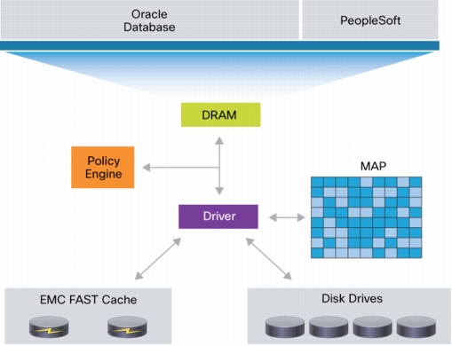
In traditional storage arrays, the DRAM caches are too small to maintain the active data for long periods of time. Very few storage arrays have an option to nondisruptively expand the DRAM cache, even if they support DRAM cache expansion. EMC FAST Cache extends the cache available to customers by up to 2 TB using flash drives. EMC FAST Cache tracks the data activity rate at a 64-KB chunk size and copies chunks to the flash drives when activity reaches a certain threshold. After a data chunk is copied to EMC FAST Cache, subsequent accesses to that chunk of data are served at flash-memory latencies. Eventually, when the data becomes less active, the data chunks are evicted from EMC FAST Cache and replaced by newer active data. EMC FAST Cache uses a simple least recently used (LRU) mechanism to evict the data chunks.
EMC FAST Cache is built on the premise that the overall applications' latencies can improve when the most frequently accessed data is maintained on a relatively smaller size, but faster, storage medium such as a flash drive. EMC FAST Cache identifies the most frequently accessed data that is temporal in nature and copies it to the flash drive automatically and nondisruptively. The data movement is completely transparent to applications, thereby making this technology application agnostic and management free. For example, EMC FAST Cache can be enabled or disabled on any storage pool simply by selecting or clearing the FAST Cache storage pool property in Advanced Settings.
EMC FAST Cache can be selectively enabled on a few or all storage pools within a storage array, depending on application performance requirements and service-level agreements (SLAs).
EMC FAST Cache offers these features:
• It can be configured in read-write mode, which allows the data to be maintained on a faster medium for longer periods, regardless of the application read-to-write mix and data rewrite rate.
• It is created on a persistent medium such as a flash drive, which can be accessed by both storage processors. In the event of a storage processor failure, the surviving storage processor can simply reload the cache rather than having to completely repopulate it by observing the data access patterns again, which is a differentiator.
• It is completely nondisruptive. To enable it, simply select the flash drives that are part of EMC FAST Cache; it does not require any array disruption or downtime.
• Since EMC FAST Cache is created on external flash drives, adding EMC FAST Cache does not consume any additional PCIe slots in the storage processor.
EMC FAST Virtual Pools (VP) is a policy-based autotiering solution for enterprise applications. EMC FAST VP operates at a granularity of 1 GB, referred to as a slice. The goal of EMC FAST VP is to efficiently use storage tiers to lower customers' total cost of ownership (TCO) by tiering less active slices of data to high-capacity drives, such as NL-SAS, and increasing performance by keeping more active slices of data on high-performance drives, such as flash drives. This storage occurs automatically and is transparent to the host environment. High locality of data is important to achieve the benefits of EMC FAST VP. When EMC FAST VP relocates data, it moves the entire slice to the new storage tier. To successfully identify and move the correct slices, EMC FAST VP automatically collects and analyzes statistics prior to relocating the data. Customers can initiate the relocation of slices manually or automatically by using a configurable, automated scheduler that can be accessed from the EMC Unisphere management tool. The multi-tiered storage pool allows EMC FAST VP to fully utilize all three storage tiers: flash memory, SAS, and NL-SAS. The creation of a storage pool allows multiple RAID groups, using different storage tiers, to be aggregated into one object. The logical unit numbers (LUNs) created from the storage pool can be either thickly or thinly provisioned. These pool LUNs are no longer bound to a single storage tier. Instead, they can be spread across different storage tiers within the same storage pool. If you create a storage pool with one tier (flash memory, SAS, or NL-SAS), then EMC FAST VP has no effect on the performance of the system. To operate EMC FAST VP, you need at least two tiers.
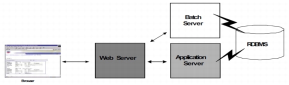
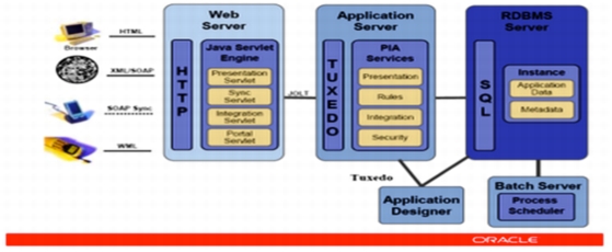
As Figure 3 shows, Oracle PIA is a standard three-tier architecture technology stack, with a web server, application server, and a database server. Although all three layers of Oracle PIA can be installed on a single server, this is usually done in a small production environment. Ideally, each Oracle PeopleSoft application module should be placed in its own three-tier technology stack. If you plan to implement Oracle PeopleSoft Human Resources Management System (HRMS) and Financials and Supply Chain Management (SCM), then you should have separate three-tier technology stacks: one for Oracle PeopleSoft HRMS and one Oracle PeopleSoft Financials and SCM. For more information, see PeopleTools 8.51: PeopleSoft Internet Architecture Administration. http://docs.oracle.com/cd/E18377_01/psft/acrobat/pt851tsvt-b0810.pdf
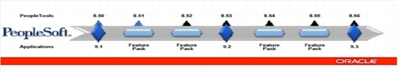
PeopleTools is the foundation on which PeopleSoft is built and run. PeopleTools should be first compatible with the Operating System Version for any Application of PeopleSoft to function smoothly.
Figure 4. Oracle PeopleTools Versions
Oracle PeopleTools is a collection of development tools. The application engine is used as the runtime engine to run Oracle PeopleSoft applications on the application server. The Designer tool is used to build and customize Oracle PeopleSoft applications. The Data Mover moves or loads data, and PeopleCode is the C++ code used in the business logic.
Figure 5 shows the individual components of Oracle PIA at a higher level.
Figure 5. Oracle PeopleSoft Architecture Overview
To build the right configuration for the implementation of Oracle PeopleSoft discussed in this document, you need to understand the role of each component in the three-tier technology stack.
External Web Server and Proxy Server
The external web server and proxy server are used when there are external users logging into the Oracle PeopleSoft application through the Internet and there is no enterprise portal.
SSL encryption is a critical resource-intensive activity that can be handled either by the firewall or by the reverse proxy server (RPS). It is always better to offload the SSL encryption activity. For SSL encryption and authentication, you must download digital certificates. Some vendors that provide these digital certificates are VeriSign, Baltimore Technologies, and Entrust. Oracle has also certified the use of the following HTTP servers as RPSs:
• With Oracle WebLogic, the certified HTTP servers are:
– Microsoft Internet Information Services (IIS)
– Sun Java System web server
– Apache HTTP server
– Oracle HTTP Server
• With IBM WebSphere, the certified HTTP server is IBM HTTP Server (IHS).
Internal Web Server
The Oracle PeopleSoft web application server is generally a Java 2 Platform, Enterprise Edition (J2EE) server. Previously, Oracle used its own Oracle Application Server, but with the integration of BEA WebLogic Oracle now recommends and certifies only the following two web application servers for use in the web layer:
• Oracle WebLogic
• IBM WebSphere
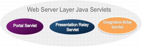
The J2EE web server is the connection to the external world (browsers) to service all its transaction requests. The J2EE server in turn connects to the application server for messaging using the application server Oracle Tuxedo and Oracle Jolt. The J2EE server is basically a collection of Oracle PeopleSoft Java servlets (Java programs that are run by the servlet engine) designed to handle a wide range of Oracle PeopleSoft transactions (Figure 6).
Figure 6. Web Server Java Servlets
Table 1 defines the servlets shown in Figure 6.
Table 1. Web Server Layer Java Servlets
Portal servlet
This servlet handles all HTTP inbound and outbound traffic from users and clients. It also manages all aspects of the Oracle PeopleSoft portal such as search, content management, and homepage personalization.
Presentation relay servlet
This servlet relays the communication received from the inbound traffic to the query and component processors to run the transaction in Oracle Tuxedo.
Integration relay servlets
This servlet is for third-party integration activities. It basically receives and transacts XML requests for integration services.
Application Server Tier
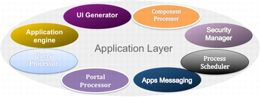
The application server is the core of Oracle PIA. The application server consists of numerous Oracle PeopleSoft services and server processes that handle transaction requests. After a request is received from the web server through Oracle Jolt, the application server runs the business logic required and generates appropriate SQL queries, which are sent across the data base server using Oracle Tuxedo. The application server connects to the Oracle PeopleSoft database and handles almost all SQL-intensive interactions with the database server that are required to process a transaction request from a user (Figure 7).
Figure 7. Oracle PeopleSoft Application Server
Table 2 lists the Oracle PeopleSoft application layer services.
The engine runs application engine processes. In Oracle PeopleSoft, this is a runtime engine.
Portal processor
The portal processor services all requests received from the portal servlet.
User interface generator
The UI generator generates the required outbound markup language format and the appropriate scripting based on the activated client action.
Application messaging processor
This processing engine manages the publication, subscription, and delivery of application messages.
Business interlink processor
This processor integrates the business interlink plug-ins required for third-party systems.
Component processor
This query execution engine runs core application business logic functions.
Process scheduler
The process scheduler is one of the most important components of the application layer. It is used to schedule batch processes and any reports scheduled by the user.
Query processor
The query processor runs the queries.
Security manager
The security manager authenticates inbound users either through the identity manager or using Lightweight Directory Access Protocol (LDAP) services.
Oracle Jolt is another companion product that coexists with the application services. It is Oracle Jolt that communicates with the web server, and without it the application layer cannot function. Oracle Tuxedo runs in a C++ environment, and Oracle Jolt extends Oracle Tuxedo's capabilities to the Internet. All servlets are configured to direct requests from the web server to a predefined Oracle Jolt port on the application server. These requests are HTTP requests to the page servlet running on the web server that translates the HTTP request into an Oracle Jolt request that is sent to a specified Oracle Jolt port. The application server runs the business logic requested by using Oracle Tuxedo, which in turn runs the appropriate SQL queries against the database.
Database Server Tier
The database server is the repository that hosts Oracle PeopleSoft metadata and user tables and indexes. The database also has temporary tablespaces for query processing such as sorting, merging, and hashing activities. It also hosts the redo and undo spaces. The servers that host Oracle PeopleSoft databases need sufficient processing, storage, and networking resources to handle the database requests, store the data and transaction logs, and communicate freely with the clients of this data.
Batch Server
The batch server hosts the Oracle PeopleSoft process schedulers. Batch servers are dedicated to the processing of batch jobs. Usually the batch server is included in the application server, but large production shops separate batch processes from the database tier to spread out the workload and reduce the computing pressure on the application layer.
Oracle PeopleSoft HRMS 9.0 Components
Before beginning an implementation of Oracle PeopleSoft on Cisco UCS servers, you must compile and document all relevant data that would reduce time and cost. You must verify that you have all the latest patches available, certified combinations of Oracle PeopleSoft and OS versions, and OS patch and kernel levels required and identify the maintenance schedule for upcoming Oracle PeopleTools and application releases of Oracle PeopleSoft HRMS. Maintenance schedules are posted on My Oracle Support. The Enterprise PeopleTools 8.51 Hardware and Software Requirements guide http://docs.oracle.com/cd/E18373_01/psft/acrobat/PeopleTools_8.51_HardwareSoftwareGuide.pdf provides an overview of Oracle PeopleSoft architecture as well as general information about the hardware and software required for a successful installation.
Hardware Components
Table 3 lists the hardware components used to deploy Oracle PeopleSoft for benchmarking on the Cisco UCS platform.
Table 3. Hardware Components
Technical Layer
Cisco UCS Server
CPU Type
Memory
Interface
External web server
Cisco UCS B200 M2
2 Intel Xeon E5620 4C/8T
12 GB
• Cisco UCS M81KR
• EMC PowerPath
Web server
Cisco UCS B200 M2
2 Intel Xeon E5620 4C/8T
96 GB
• Cisco UCS M81KR
• EMC PowerPath
Application server
Cisco UCS B200 M2
2 Intel Xeon X5675 6C/12T
96 GB
• Cisco UCS M81KR
• EMC PowerPath
Database server
Cisco UCS B250 M2
2 Intel Xeon X5680 6C/12T
394 GB
• Cisco UCS M81KR
• EMC PowerPath
Fabric interconnects
Cisco UCS 6120XP
CNA switches
Cisco Nexus 5548P or 5548UP Switch
Cisco UCS blade chassis
Cisco UCS 5100 Series
• 2x I/O modules
• 4x power supplies
Before choosing the Cisco UCS servers, you should check the interoperability matrices for Cisco UCS components and configurations that have been tested and validated by Cisco, by Cisco partners, or both.
Oracle PeopleSoft HRMS 9.1 with Feature Pack December 2010
Database server
Oracle 11.2.0.2.0
Database client
Oracle 11.2.0.2.0
Oracle WebLogic
Oracle WebLogic 10.3.4.0.0
Oracle Tuxedo 10.3.0.0.0
Oracle Tuxedo 10gR3 RP031 64-bit
Micro Focus Server Express 5.1 for COBOL
Micro Focus Server Express 5.1 64-Bit with Wrap Pack 4
Java Runtime Environment (JRE)
Java Version 1.6.0_20
Java SE Runtime Environment (Build 1.6.0_20-b02)
Java HotSpot 64-Bit Server Virtual Machine (Build 16.3-b01, mixed mode)
Please check the latest hardware and software guides for the required release of Oracle PeopleTools before downloading and installing Oracle PeopleSoft.
Cisco UCS Reference Architecture for Oracle PeopleSoft: No Single Point of Failure
The reference architecture shown in Figure 8 is Cisco's recommended architecture for running Oracle PeopleSoft on Cisco UCS in a production environment. This high-level diagram shows the number of web, application, and database servers typically used in a three-tier technology stack required to avoid introduction of a single point of failure (SPoF).
Figure 8. Cisco UCS Reference Architecture or Oracle PeopleSoft
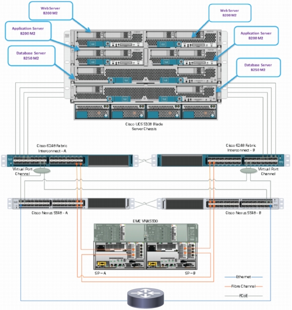
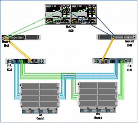
Cisco UCS and Oracle PeopleSoft Deployment Layout
Figure 9 shows the Cisco UCS layout used in the Oracle PeopleSoft benchmark activity. It shows the eight I/O modules pulled out of the chassis and plugged into the Cisco UCS 6120XP Fabric Interconnect. The connections of the Cisco Nexus 5000 Series Switches to the fabric interconnects and to the EMC VNX 5500 are also shown.
Figure 9. Cisco UCS and Oracle PeopleSoft Deployment Layout
Cisco UCS Configuration
This section details the Cisco UCS configuration that was performed as part of the infrastructure buildout for deployment of Oracle PeopleSoft HRMS 9.0 on RHEL 5.6 and EMC VNX SAN storage. The racking, power, and installation of the chassis are beyond the scope of this document (they are described in the installation guide at http://www.cisco.com/en/US/docs/unified_computing/ucs/hw/chassis/install/ucs5108_install.html) More details about each step can be found in the following documents:
Pools are the building blocks for providing unique identification of hardware resources. As the basis for the utility computing model, they allow service profiles to be associated with any blade, while providing the exact same ID and presentation to the upstream LAN and SAN. Three sets of pools are used as part of Cisco UCS best practices:
• UUID pools: Provide IDs, similar to a serial number or service tag
• Worldwide node name (WWNN) and worldwide port name (WWPN) pools: Provide unique IDs for Fibre Channel resources on servers (Fibre Channel nodes and ports)
• MAC address pools: Provide unique IDs for virtual network interface ports
Cisco UCS assigns MAC addresses, management IP addresses, and WWN addresses using a pool mechanism. These pools are all functionally organized, with UUID pools maintained from the Server tab, WWNN and WWPN pools maintained from the SAN tab, and MAC address pools maintained from the LAN tab. Cisco UCS Manager disperses the pools using service profiles. All pools need to be set up before you create any of the profiles to be assigned.
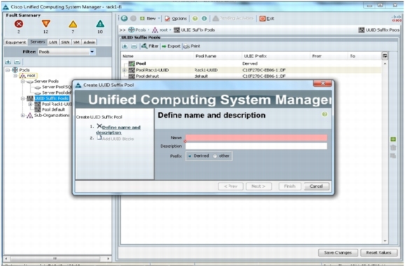
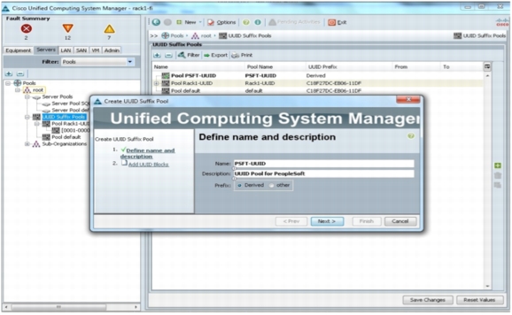
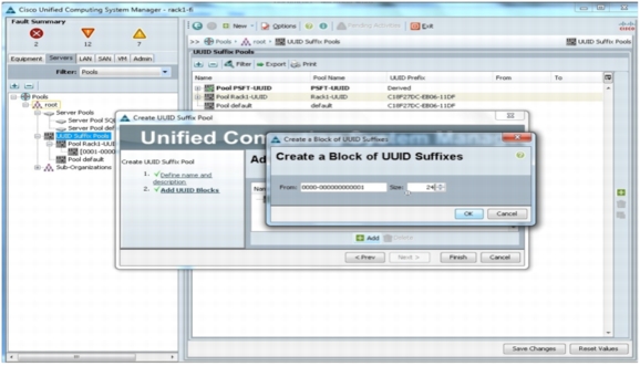
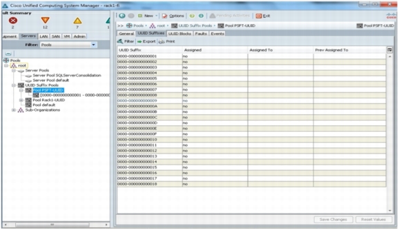
Create UUID Pool from Server Tab
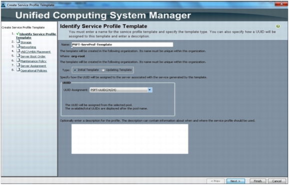
The first string of digits constitutes the prefix of the UUID and is fixed. The remaining digits, the UUID suffix, are variable.
A UUID suffix pool helps ensure that these variable values are unique for each server associated with a service profile that uses that particular pool and helps prevent conflicts.
If UUID suffix pools are used in service profiles, the UUID of the server associated with the service profile does not need to be manually configured.
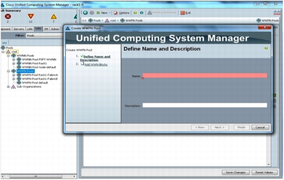
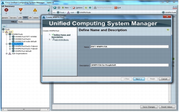
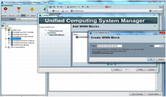
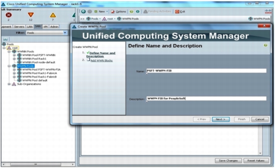
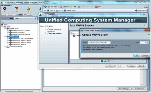
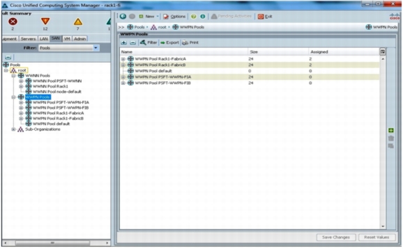
Create WWPN Pool from SAN Tab
From the WWPN pools, unique pools will be created for each fabric.
For the address convention, the following is used:
• 20:00:00:25:b5 (do not change)
• 02 (identifies this system)
• 0A (the fabric identifier)
• 00 (start of available addresses; up to 255)
Repeat the exact same steps for the second fabric except change the fabric identifier to 0B and change the specific name.
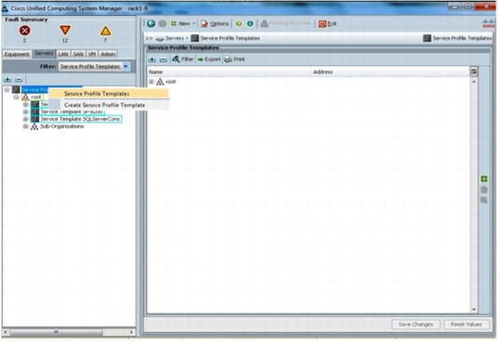
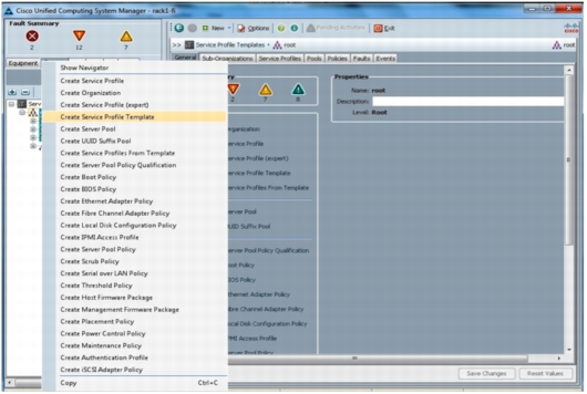
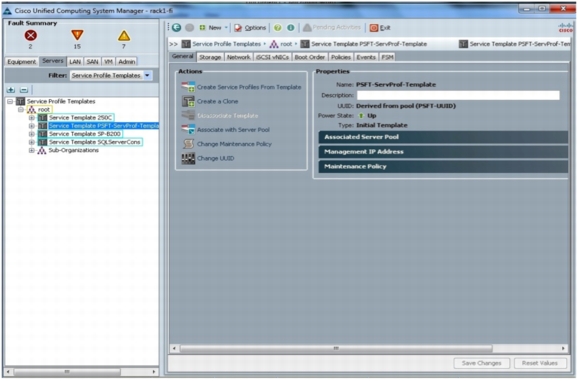
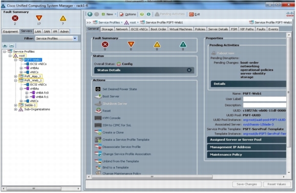
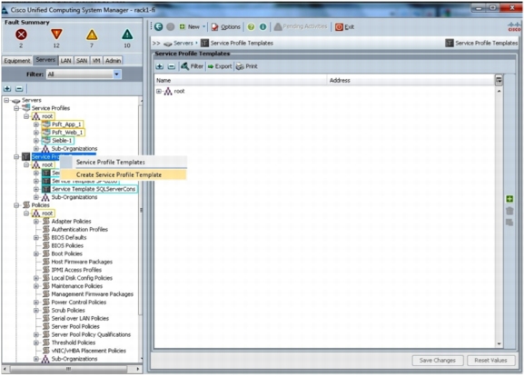
Create Service Profile Template
To understand blade management in Cisco UCS, you need to understand the service profile, or logical server. The service profile represents a logical view of a single blade server, without the need to know exactly which blade is discussed. The profile object contains the server personality: for example, identity and network information. The profile can then be associated with a single blade at a time.
The concept of profiles was created to support the notion of logical server mobility, or the transfer of identity transparently from one blade to another, as well as the pooling concept. Even if a service profile is intended to manage a blade server as a traditional individual server and the benefits of mobility and pooling are not used, a service profile for a blade will still need to be created and managed. Although a blade can be booted without a service profile, it will not have network or SAN connectivity.
A Cisco UCS service profile contains the following information:
• Identity information for server (UUID)
• WWNN (serverwide)
• LAN and SAN configuration (through virtual NIC [vNIC] and virtual HBA [vHBA] configuration)
– NIC and HBA identity (MAC address and WWN)
– Ethernet NIC profile
– VLAN and VSAN configuration information
– Boot order
– Various policies
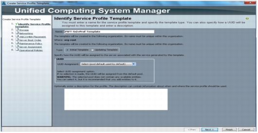
Identify Service Profile
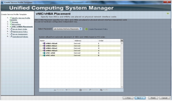
Cisco UCS Manager provides templates for the primary objects (vNICs, vHBAs, and service profiles) to facilitate reuse and rapid deployment. Properties, attributes, and policies can be defined at the template level, helping enable rapid instantiation and provisioning.
Best practices include:
• Use expert mode when creating service profile templates to have the most control and definition capabilities in the utility computing model.
• When creating templates, draw from the subordinate pools and policies that have been previously defined.
Create vHBA Template (Attach Storage Configuration to Template)
vNICs and vHBAs are the most difficult parts of service profiles to create. vNICs are identified with MAC addresses, and vHBAs are identified with WWNs.
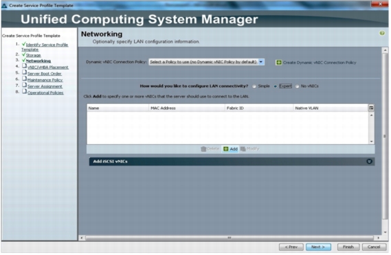
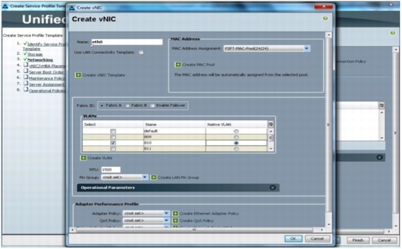
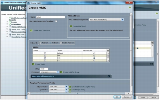
Create vNIC Template (Attach Network Configuration to Template)
vNIC and vHBA resources are always associated with a specific fabric interconnect (A side or B side). A typical service profile has at least two vNICs and vHBAs: one bound to each side. vNIC (or vHBA) templates can be used to encapsulate both the MAC address pool (or WWPN pool) association and the fabric ID.
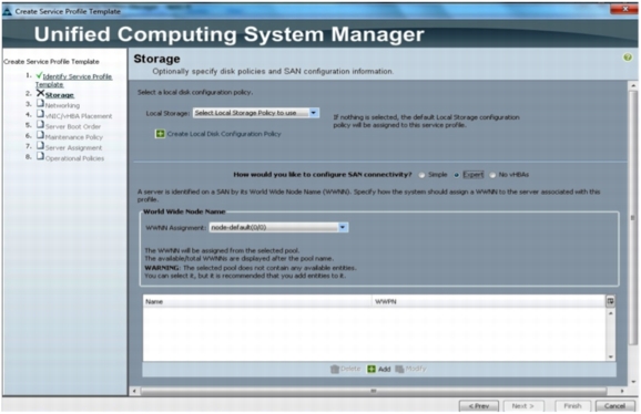
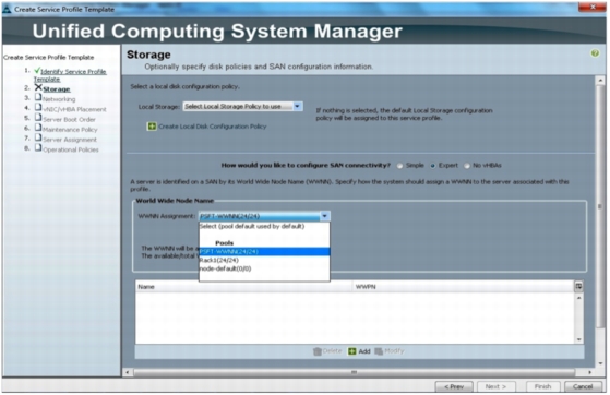
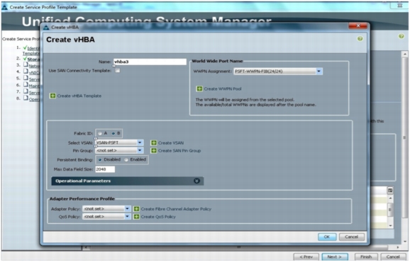
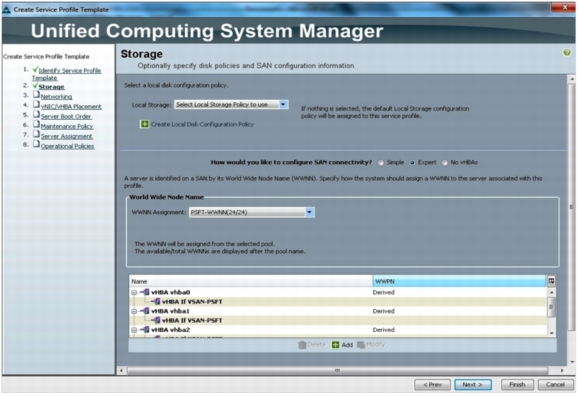
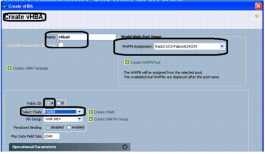
Create vHBA in Expert Mode
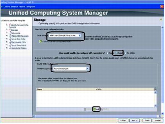
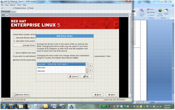
In the Storage Configuration Screen, do the following
1. Do not select any local Disk policy. You are doing a SAN Boot for the B230/B250 Server and the RAID policy configured in the Storage LUN is to be used.
2. Select Expert mode in SAN Connectivity option.
3. Assign WWNN from the WWNN pool configured in the previous section.
4. Click Add to assign WWPN for vHBA's
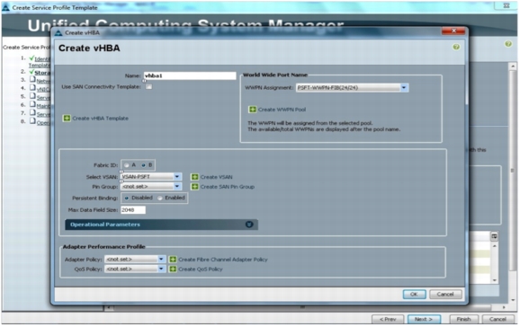
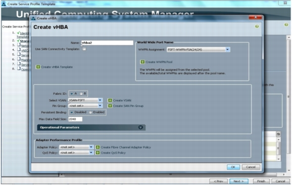
The vHBA for SANBoot Installation are mapped to Fabric A and Fabric B respectively. This allows redundancy at the Fabric interconnect level. To configure vHBA screen:
• Select the WWPN pool as configured in the previous section. You have configured different WWPN pools for Fabric A and Fabric B. So this has to be selected as per the Fabric IS selected
• Select Fabric ID as "A", select Fabric ID as "B" for vHBA2
• Select VSAN as configured previously
• Follow same steps for the other three vHBA
Go to next screen, Networking , and do the following to specify the LAN configuration:
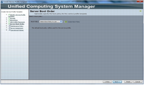
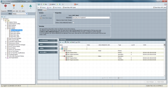
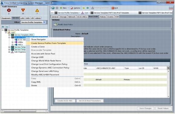
Attach Boot Policy Configuration to Template
Boot policy defines the boot devices and methods and boot order.
• Place CD-ROM first in the boot order, for emergency recovery.
• For SAN boot, define separate boot policies for each storage array that serves boot LUNs.
• For network or PXE boot, define LAN or vNIC boot as last in the boot order, following either SAN or local boot.
After the service profile template is created, you can create the boot policy; see
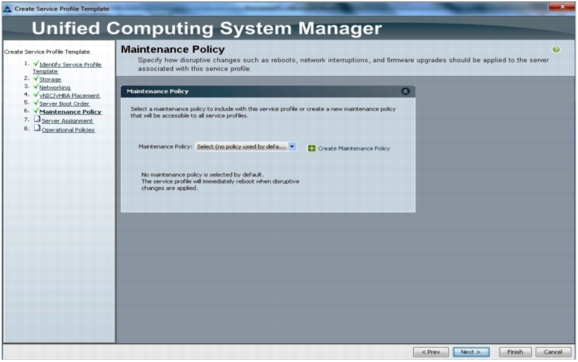
Attach Maintenance Policy Configuration to Template
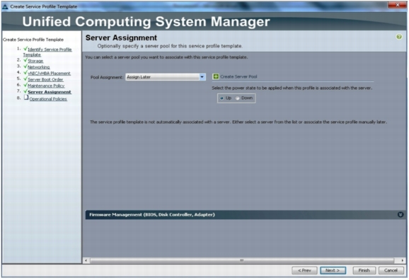
Attach Server Assignment Configuration to Template
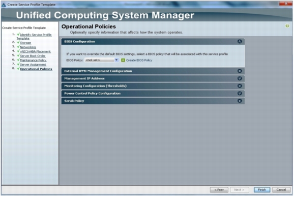
Attach Operational Configuration to Template
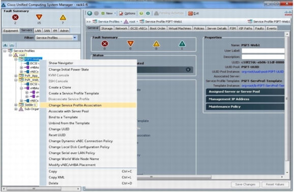
Create Service Profile from Service Profile Template
Note: Updating Templates
Cisco UCS templates have a very powerful property called updating templates. Updating templates allow changes in the template, such as pools or policies, to be propagated immediately to any higher-level template or service profile (whether instantiated or not). However, changes reflected to instantiated service profile through updating templates may cause a service interruption or server reboot. Therefore, you should use updating templates with the greatest level of awareness and caution. Updating templates can be tremendous time-saving assets during a scheduled maintenance window. However, updating templates can also have disastrous results when used during normal operations.
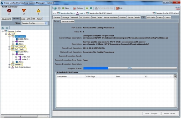
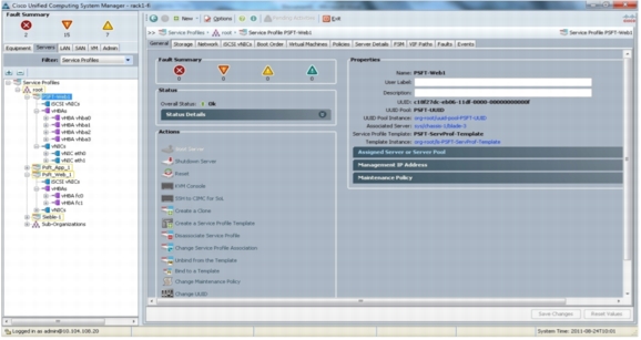
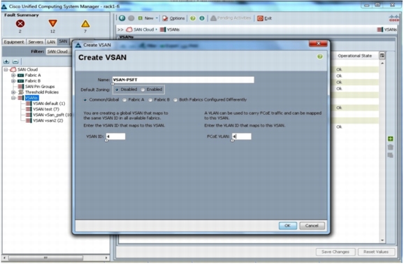
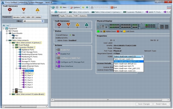
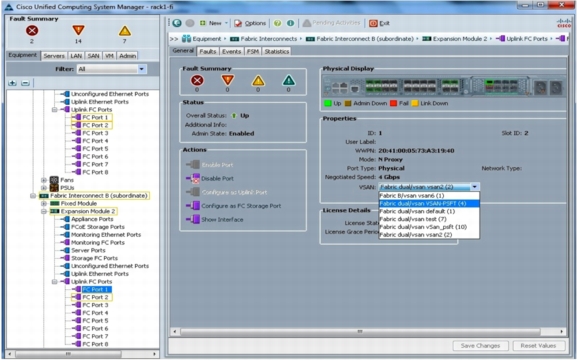
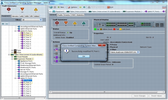
Associate Servers with Service Profile
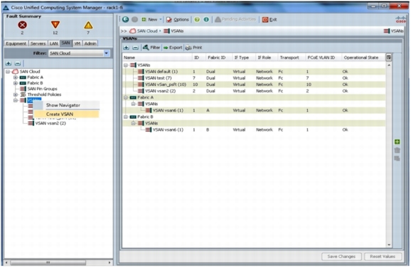
Get a free VSAN ID from the Cisco Nexus 5000 Series Switch before creating a new VSAN for Oracle PeopleSoft.
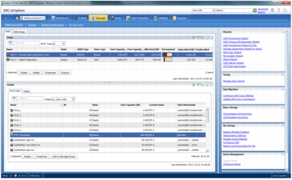
EMC VNX Storage Configuration
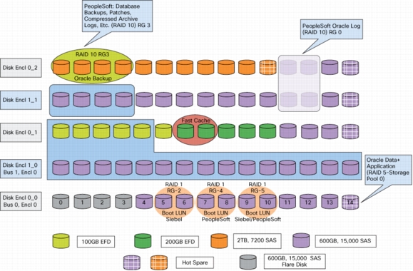
Figure 11 shows the disk layout of the EMC VNX5500 used in this Oracle PeopleSoft use case.
Figure 10. EMC VNX Disc Layout
Configuring Multipathing with EMC PowerPath/VE
EMC PowerPath/VE is host-based software that provides multipathing capability to help ensure QoS for VMware vSphere users by delivering business continuity and availability as well as performance to meet SLAs. EMC PowerPath/VE automates data path use in dynamic VMware virtualized environments to provide predictable and consistent information access while delivering investment protection with support for heterogeneous servers, operating systems, and storage.
Increasingly, deployments are using virtualization for consolidation and to enable scale-out of mission-critical applications. EMC PowerPath/VE manages the complexity of large virtual environments, which may contain hundreds or thousands of independent virtual machines running computation-intensive I/O applications. To manually configure this type of scenario, making sure that all the virtual machines get the I/O response time needed, is very difficult and time consuming. If other variables, such as VMware vMotion and the need for high availability in the VMware environment are requirements, any assumption about which I/O streams will be sharing which channels are invalidated. EMC PowerPath/VE manages this complexity, adjusting the I/O path use to address changes in I/O loads coming from the virtual machines. You simply assign all devices to all paths. and EMC PowerPath/VE then does the work, optimizing overall I/O performance for the virtual environment.
The main benefits of using EMC PowerPath/VE in a VMware vSphere 5 environment include the capability to manage these large environments and increase performance by helping ensure optimal use of resources, while also providing high availability, automating I/O path failover, and enabling recovery in the event of a path failure.
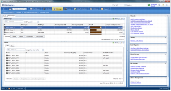
Create Raid Groups for Oracle Application Binaries
Create a Storage Pool for the PeopleSoft (PSFT) Database (RAID5)
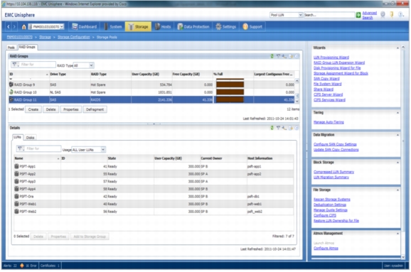
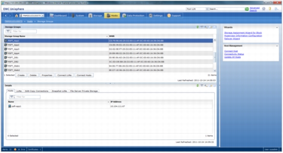
Create Storage Group and Attach Hosts
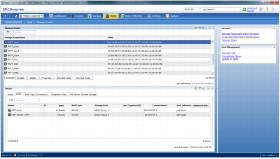
Create Storage Group and Attach LUNs
Configuring the Cisco Nexus Switch
Cisco Nexus switches are connected to the blade chassis with the I/O modules (2 x 4 cables) brought out and connected to the switch. From the fabric interconnect, the FCoE cables are drawn out and patched to the Cisco Nexus 5000 Series CNA switch. The Cisco Nexus 5000 Series Switch is also connected to EMC VNX. The uplink to the external world is from the Cisco Nexus 5000 Series Switch.
Creating the Zone and Zoneset
Log on to the Cisco Nexus 5000 Series Switch.
Log on to the Cisco UCS Manager (Capitola).
List the WWPN that appears in the Cisco Nexus 5000 Series database.
VSAN 4 is the zone in which the Oracle PeopleSoft servers are accommodated.
Creating a File System Partition on the Oracle PeopleSoft Servers
List the connected hard disks and their partitions:
[root@psft-db1 ~]# fdisk -l
Partition the disk with fdisk:
Enter the following in the order shown:
(n > p > 1 > default value > default value > p > w)
[root@psft-db1 ~]# fdisk /dev/sdk
Device contains neither a valid DOS partition table, nor Sun, SGI or OSF disk label
Building a new DOS disk label. Changes will remain in memory only, until it is decided to write them. After that, of course, the previous content will not be recoverable.
The number of cylinders for this disk is set to 39162.
There is nothing wrong with that, but this is larger than 1024, and could in certain setups cause problems with:
• Software that runs at boot time (such as old versions of LILO)
• Booting and partitioning software from other OSs (such as DOS FDISK or OS/2 FDISK)
Warning: Invalid flag 0x0000 of partition table 4 will be corrected by w(rite).
Command (m for help): n
Command action
e extended
p primary partition (1-4)
p
Partition number (1-4): 1
First cylinder (1-39162, default 1):
Using default value 1
Last cylinder or +size or +sizeM or +sizeK (1-39162, default 39162):
Using default value 39162
Command (m for help): w
The partition table has been altered!
Calling ioctl() to re-read partition table.
Syncing disks.
Create a file system
After creating the partition is created, a filesystem (format) can be overlaid using the mkfs command as shown here.
[root@psft-db1 ~]# mkfs -t ext3 /dev/sdk
Add the filesystem created to fstab
[root@psft-db1 ~]# vi /etc/fstab
Add "/dev/sdk /db2-data ext3 defaults 0 0"
LABEL=/ / ext3 defaults 1 1
LABEL=/boot /boot ext3 defaults 1 2
devpts /dev/pts devpts gid=5,mode=620 0 0
/dev/sdk /db2-data ext3 defaults 0 0
tmpfs /dev/shm tmpfs defaults 0 0
proc /proc proc defaults 0 0
sysfs /sys sysfs defaults 0 0
Create a directory
[root@psft-db1 ~]# mkdir /db2-data
Mount the directory
[root@psft-db1 ~]# mount /db2-data
[root@psft-web1 host4]# mkfs -t ext3 /dev/sdk
mke2fs 1.39 (29-May-2006)
Filesystem label=
OS type: Linux
Block size=4096 (log=2)
Fragment size=4096 (log=2)
39321600 inodes, 78642183 blocks
3932109 blocks (5.00%) reserved for the super user
Writing superblocks and filesystem accounting information: done
This filesystem will be automatically checked every 27 mounts or
180 days, whichever comes first. Use tune2fs -c or -i to override.
Remember:
Now > vi /etc/fstab
Add "/dev/sdc1 /db2-data ext3 defaults 0 0" in fstab
Then > mkdir /db2-data
Then > mount /db2-data
Installation of Oracle PeopleSoft on Cisco UCS
An Oracle PeopleSoft Enterprise Server requires creation of a standard UNIX system user account: for example, psoft. This account must be available on each Oracle PeopleSoft server in your enterprise under which Oracle PeopleSoft processes and components operate. Use the following guidelines to create the Oracle PeopleSoft service owner account:
• The Oracle PeopleSoft service owner account must be defined or available on each applicable server: on each application server, on each web server, and on each process scheduler.
• The Oracle PeopleSoft owner account password must not require a change on the next logon and must be set so that it does not expire.
• The Oracle PeopleSoft owner account name or password cannot contain any spaces.
Prerequisites
• A root user and a nonroot user (psoft) are needed to perform any installation tasks on the Linux devices.
• Root user credentials are required to create the required Oracle PeopleSoft or Oracle users.
• Required file systems must be configured to install Oracle Tuxedo, WebLogic, PeopleTools, and Database.
• Use the Oracle PeopleSoft certification matrix to identify the required software and versions.
• All the required software must be downloaded.
• Network connectivity must be established between all the devices involved.
• JRE Version 1.6.0_20 must be installed on each server on which Oracle PeopleSoft components will be installed.
• Oracle database software must be installed on the device that will host the Oracle PeopleSoft database.
• The Oracle client must be installed on all devices that will host Oracle PeopleSoft servers.
• Database connectivity must be established between devices that will host Oracle PeopleSoft servers and the Oracle server.
• Set umask to 027 on the installation directory.
Creating an Oracle PeopleSoft Service Account
The Oracle PeopleSoft Enterprise Server requires creation of a standard UNIX system user account: for example, psoft. This account must be available on each Oracle PeopleSoft server in your enterprise under which Oracle PeopleSoft processes and components operate. Use the following guidelines to create the Oracle PeopleSoft service owner account:
• The Oracle PeopleSoft service owner account must be defined or available on each applicable server: on each application server, on each web server, and on each process scheduler.
• The Oracle PeopleSoft owner account password must not require a change on the next logon and must be set so that it does not expire.
• The Oracle PeopleSoft owner account name or password cannot contain any spaces.
General Installation Requirements
The following general requirements must be met before Oracle PeopleSoft Enterprise Server is installed:
• Choose a load-balancing strategy.
• Make sure that the disk space is sufficient for the installation.
• Make sure that the database server software is installed on the Oracle PeopleSoft database server.
• Make sure that the database client software is installed in other Oracle PeopleSoft servers such as application servers and web servers.
• Install database server and client prior to installing the Oracle PeopleSoft server components as required.
• Install all the third-party software required for Oracle PeopleSoft (JRE, JDK, etc.).
• Create directories for the Oracle PeopleSoft software and PeopleSoft file system on the Linux machine.
• Make sure that enough temporary disk space is available for the installers and wizards.
• If the you are installing Oracle PeopleSoft products in GUI mode, set the DISPLAY variable to display the Java Installer user interface on the machine.
• If you are installing in console mode, specify the =-console parameter during the installation procedure.
Installation Requirements Specific to UNIX and Linux
• Installation can be performed either as root or as a nonroot user. In most cases, installation should be performed by a nonroot user, for simpler administration and maintenance.
• If the Oracle PeopleSoft application server is installed by root, then only root can stop and start the server. To avoid this requirement, an account other than root that has the authorization to install can be used. All future patch releases must be installed as the same user who installed the base installation being patched.
• If the web server is installed by the root user, then only root can stop and start the server. To avoid this requirement, use an account other than root that has the authorization to install. All future patch releases must be installed as the same user who installed the base installation being patched.
• Use VNC Viewer, xterm, or Xmanager, which is third-party software, or remote access to the Linux machine to install Oracle PeopleSoft products in GUI mode.
• Installation can be performed in console mode by specifying the parameter mode=-console during the installation.
• Set the user profiles and environment variables for Oracle and Oracle PeopleSoft.
Oracle PeopleSoft Web Server Installation
• Install JDK or jrockit jrockit-jdk1.6.0_26-R28.1.4-4.0.1 on the web server before installing the Oracle WebLogic server.
• Install Oracle WebLogic 10.3.4.0 (64-bit mode) on the web server.
• Install Oracle PeopleTools 8.51 on the web server.
• Install Oracle PeopleTools Patch 8.51.11 on the web server.
Note: Refer to Appendix A for a complete Oracle PeopleSoft web server installation listing.
Oracle PeopleSoft Application Server Installation
• Install Oracle Client 11.2.0.10 on the application server.
• Install Oracle Tuxedo 10.3.0.0 on the application server.
• Install Oracle Tuxedo Patch RP065 on the application server.
• Install Oracle PeopleTools 8.51 on the application server.
• Install Oracle PeopleTools Patch 8.51.11 on the application server.
• Install Oracle PeopleSoft HRMS 9.1 Feature Pack December 2010 on the application server.
Note: Refer to Appendix B for a complete Oracle PeopleSoft application server Installation listing.
Oracle PeopleSoft Database Server Installation
• Install Oracle Server 11.2.0.1.0 binaries on the database server.
• Install Oracle Client 11.2.0.10 on the database server.
• Install Oracle Tuxedo 10.3.0.0 on the database server.
• Install Oracle Tuxedo Patch RP065 on the database server.
• Install Oracle PeopleTools 8.51 on the database server.
• Install Oracle PeopleTools Patch 8.51.11 on the database server.
• Install Oracle PeopleSoft HRMS 9.1 Feature Pack December 2010 on the database server.
• Install Micro Focus Server Express COBOL compiler 5.1wp4
Note: Refer to Appendix C for a complete Oracle PeopleSoft database server Installation listing.
Oracle PeopleSoft Installation Port Numbers
The following port numbers are used for the workstation server listener (WSL), Oracle Jolt server listener (JSL), HTTP, and other ports:
• WSL: 7700
• JSL: 9700
• HTTP: 8700
• HTTPS: 443
• JRAD: 9100
• PSDBGSRV: 9500
• SMTP: 25
Appendix A: Oracle PeopleSoft Web Server Installation
Oracle JRockit Installation on Web Server
Log in to the Oracle PeopleSoft web server as psoft and follow the installation procedure shown here.
Note: Oracle JRockit installation was performed in console mode. The following listing shows the procedures and commands captured during the Oracle JRockit installation on the web server.
Download the jrockit28.1.4 software from Oracle My Support.
• Choose the file p12706519_2814_Linux-x86-64.zip.
• Transfer the file to the software location of the web server: /u01/softwares.
• Create a directory: /u01/bea/jrockit28.1.4.
• Unzip the software. Unzipping will extract all the files and folders into the specified directory.
The directory structure after the installation of Oracle JRockit is shown here.
[psoft@psft-web1 jrockit-jdk1.6.0_26]$ pwd
/u01/psoft/bea/jrockit28.1.4/jrockit-jdk1.6.0_26
[psoft@psft-web1 jrockit-jdk1.6.0_26]$ ls -ltr
total 18984
-rwxrwxr-x 1 psoft oinstall 19103658 May 4 10:42 src.zip
drwxrwxr-x 3 psoft oinstall 4096 May 4 10:42 include
drwxrwxr-x 8 psoft oinstall 4096 May 4 10:49 sample
drwxrwxr-x 9 psoft oinstall 4096 May 4 10:49 demo
drwxrwxr-x 2 psoft oinstall 4096 May 4 12:51 lib
-rwxrwxr-x 1 psoft oinstall 239443 Jun 17 21:30 THIRDPARTYLICENSEREADME.txt
drwxrwxr-x 4 psoft oinstall 4096 Jun 17 21:35 jre
drwxrwxr-x 2 psoft oinstall 4096 Jun 25 21:30 bin
drwxr-xr-x 6 psoft oinstall 4096 Oct 11 12:47 missioncontrol
No separate installation method or processes are needed for this installation of Oracle JRockit. Just unzipping the file in to a folder is all you need to do.
Oracle WebLogic Installation on Web Server
Log in to the Oracle PeopleSoft web server as psoft and follow the installation procedure shown here.
Note: Oracle WebLogic installation was performed in console mode. The following listing shows the procedures and commands captured during the Oracle WebLogic installation on the web server.
This installer will guide you through the installation of WebLogic 10.3.4.0.
Type "Next" or enter to proceed to the next prompt. If you want to change data entered previously, type "Previous". You may quit the installer at any time by typing "Exit".
Oracle PeopleTools 8.51 Installation on Web Server
Log in to the Oracle PeopleSoft web server as psoft and follow the installation procedure shown here.
Note: Oracle PeopleTools installation was performed in console mode. The following listing shows the procedure captured during the Oracle PeopleTools installation on the web server.
[psoft@psft-web1 ~]$ cd /u01/softwares/PT851-CDS/cd1/Disk1/InstData
Congratulations. PeopleTools has been successfully installed to:
/u01/psoft/pshome
PRESS <ENTER> TO EXIT THE INSTALLER:
Oracle PeopleTools 8.51.11 Patch Installation on Web Server
Log in to the Oracle PeopleSoft web server as psoft and follow the installation procedure shown here.
Note: Oracle PeopleTools patch installation was performed in console mode. The following listing shows the procedures and commands captured during the Oracle PeopleTools patch installation on the web server.
[psoft@psft-web1 ~]$ cd /u01/softwares/85111-PATCH/cd85111/Disk1/InstData
Congratulations. PeopleTools has been successfully installed to:
/u01/psoft/pshome
PRESS <ENTER> TO EXIT THE INSTALLER:
Appendix B: Oracle PeopleSoft Application Server Installation
Oracle Tuxedo Installation on Application Server
Log in to the Oracle PeopleSoft application server as psoft and follow the installation procedure shown here.
Note: Oracle Tuxedo installation was performed in console mode. The following listing shows the procedure captured during the Oracle Tuxedo installation on the application server.
InstallAnywhere will guide you through the Tuxedo 10gR3 installation.
It is strongly recommended that you quit all programs before continuing with this installation.
Enter "next' to proceed to the next screen. Enter "back" to modify the previous screen.
You may cancel this installation at any time by typing "quit".
WARNING: "Quitting" creates an incomplete Tuxedo 10gR3 installation. You must re-install Tuxedo 10gR3. For more information, see "Preparing to Install the
Oracle Tuxedo System" in the Tuxedo 10gR3 Installation Guide.
Congratulations. Tuxedo 10gR3 has been successfully installed to:
/u01/psoft/bea/tuxedo10gR3
PRESS <ENTER> TO EXIT THE INSTALLER:
Oracle Tuxedo Patch Installation on Application Server
Log in to the Oracle PeopleSoft application server as psoft and follow the installation procedure shown here.
Note: Oracle Tuxedo patch installation was performed in console mode. The following listing shows the procedure captured during the Oracle Tuxedo patch installation on the application server.
rpreleasenote = SUSE LINUX Enterprise Server 10 (x86_64) x86 for AMD64, 64bits Tuxedo
portreleasenotes= SUSE LINUX Enterprise Server 10 (x86_64) x86 for AMD64, 64bits Tuxedo
Installing server and client files...
Enter owner for patch files:
psoft
Enter group for patch files:
oinstall
The patch installation finished successfully.
Oracle PeopleTools 8.51 Installation on Application Server
Log in to the Oracle PeopleSoft application server as psoft and follow the installation procedure shown here.
Note: Oracle PeopleTools installation was performed in console mode. The following listing shows the procedure captured during the Oracle PeopleTools installation on the application server.
[psoft@psft-app1 ~]$ cd /u01/softwares/PT851-CDS/cd1/Disk1/InstData
Congratulations. PeopleTools has been successfully installed to:
/u01/psoft/pshome
PRESS <ENTER> TO EXIT THE INSTALLER:
Oracle PeopleTools 8.51.11 Patch Installation on Application Server
Log in to the Oracle PeopleSoft application server as psoft and follow the installation procedure shown here.
Note: Oracle PeopleTools patch installation was performed in console mode. The following listing shows the procedure captured during the Oracle PeopleTools patch installation on the application server.
[psoft@psft-app1 ~]$ cd /u01/softwares/85111-PATCH/cd85111/Disk1/InstData
Congratulations. PeopleTools has been successfully installed to:
/u01/psoft/pshome
PRESS <ENTER> TO EXIT THE INSTALLER:
Oracle PeopleSoft HRMS 9.10 Installation on Application Server
Log in to the Oracle PeopleSoft application server as psoft and follow the installation procedure shown here.
Note: Oracle PeopleSoft HRMS application installation was performed in console mode. The following listing shows the procedure captured during the Oracle PeopleSoft HRMS application installation on the application server.
[psoft@psft-app1 ~]$ cd /u01/softwares/HRMS91featurepack-dec2010/V23382-01/Disk1/InstData
[psoft@psft-app1 InstData]$ ls -ltr
-rwxrwxrwx 1 psoft oinstall 54824825 Nov 2 2010 setup.linux
-rwxrwxrwx 1 psoft oinstall 97750905 Nov 2 2010 setup.hp
-rwxrwxrwx 1 psoft oinstall 41059115 Nov 2 2010 setup.exe
-rwxrwxrwx 1 psoft oinstall 215945081 Nov 2 2010 setup.aix
-rwxrwxrwx 1 psoft oinstall 9637753 Nov 2 2010 setup.zlinux
-rwxrwxrwx 1 psoft oinstall 149426041 Nov 2 2010 setup.linux
-rwxrwxrwx 1 psoft oinstall 118656889 Nov 2 2010 setup.hp-ia64
-rwxrwxrwx 1 psoft oinstall 595646325 Nov 2 2010 sesource1.zip
-rwxrwxrwx 1 psoft oinstall 118 Nov 2 2010 MediaId.properties
Appendix C: Oracle PeopleSoft Database Server Installation
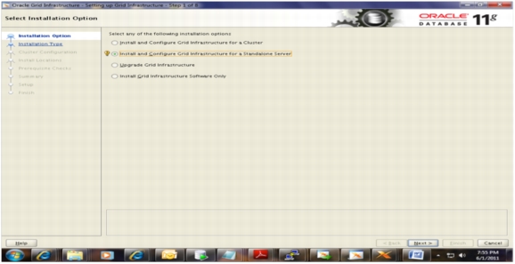
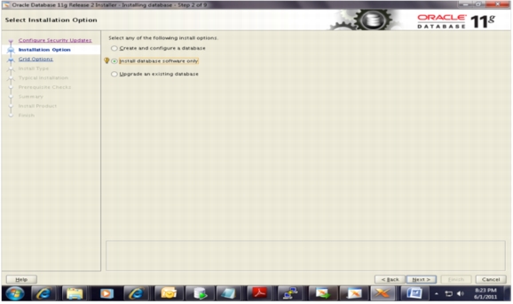
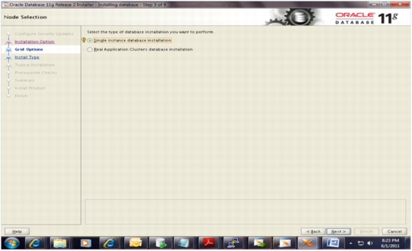
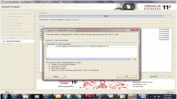
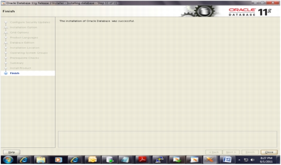
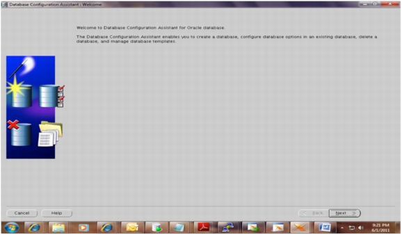
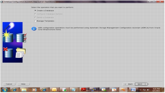
Installation of Oracle 11g r2 (11.2.0.1.0) Software Binaries on Database Server
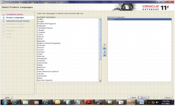
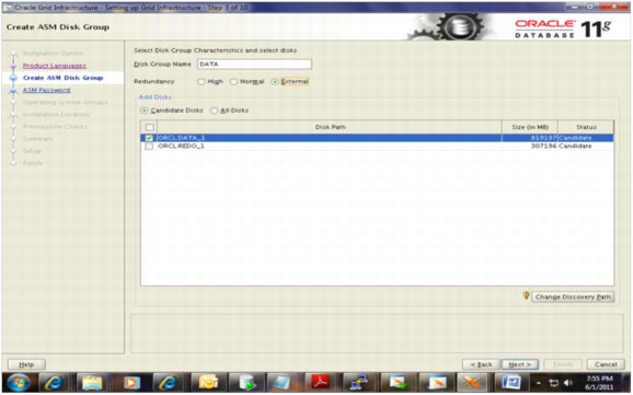
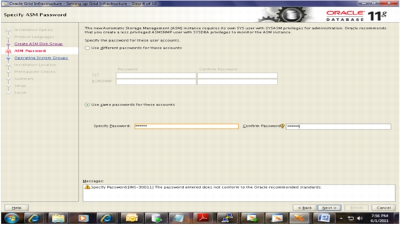
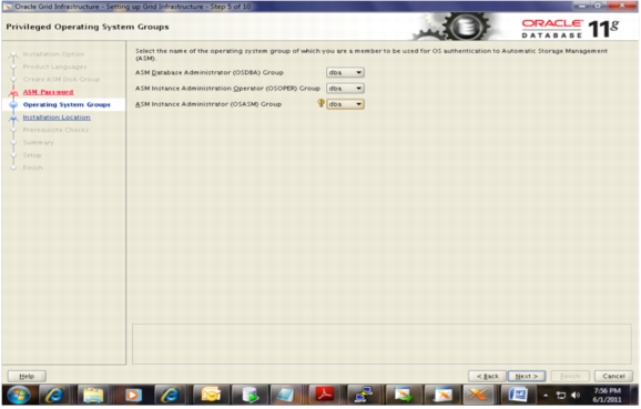
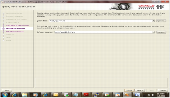
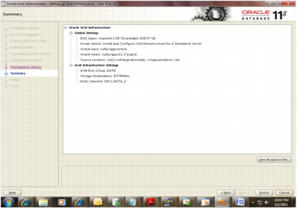
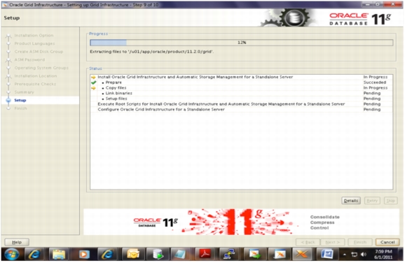
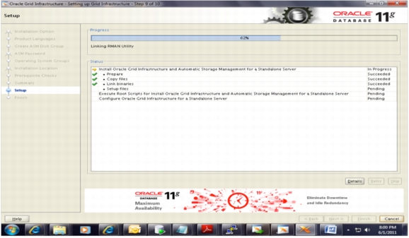
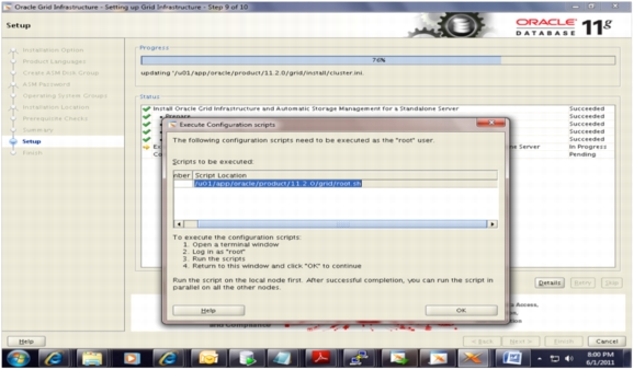
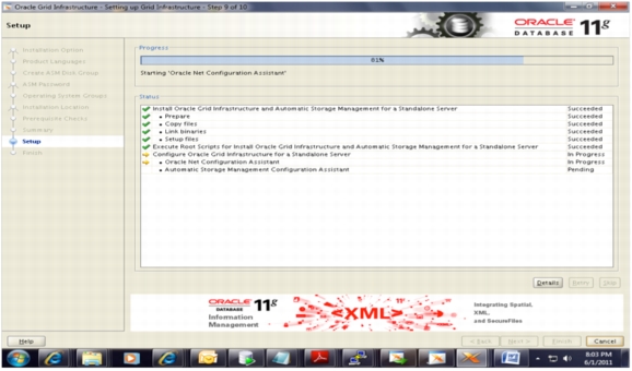
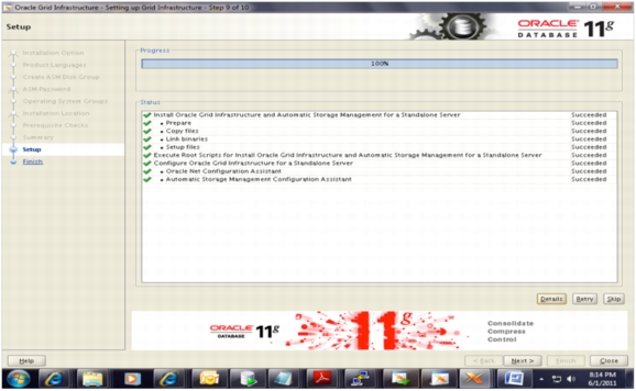
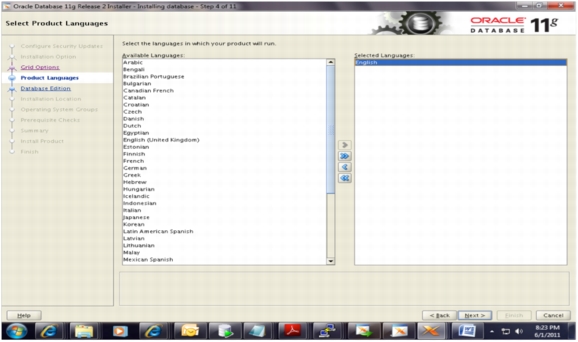
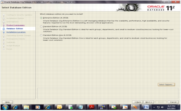
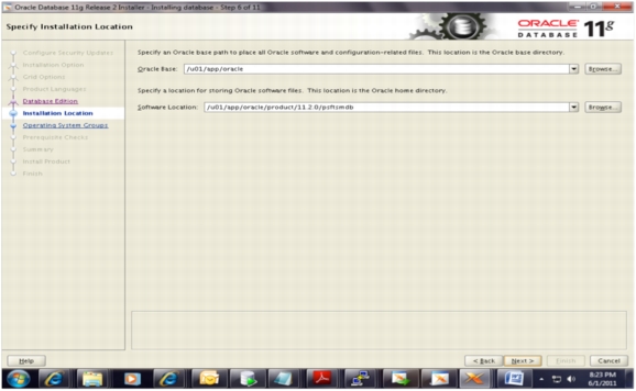
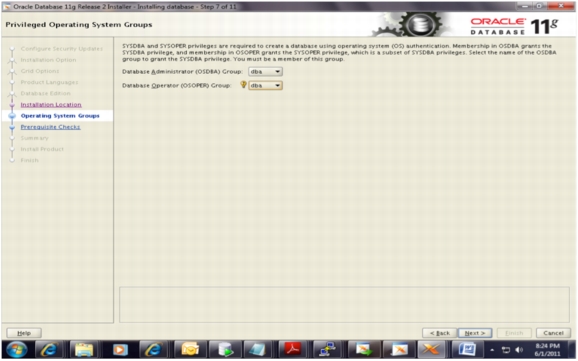
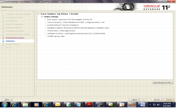
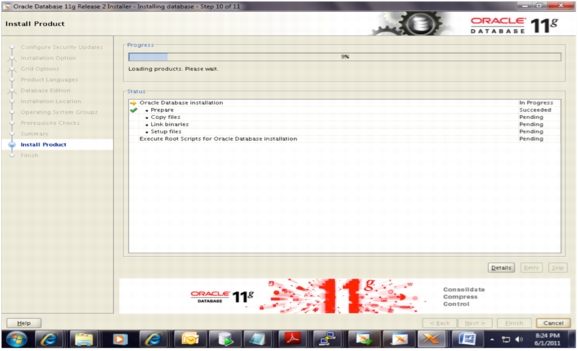
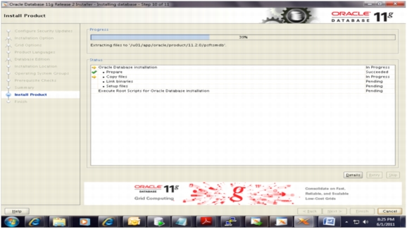
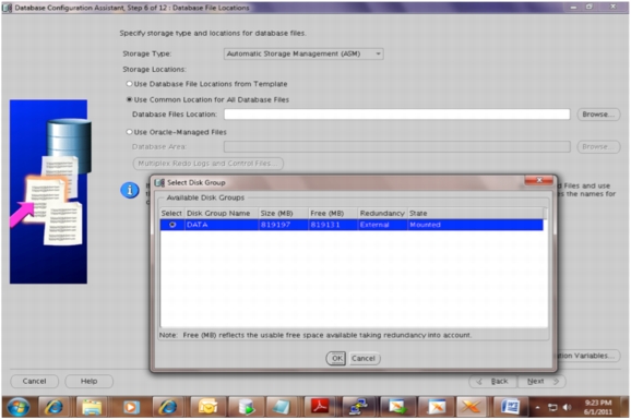
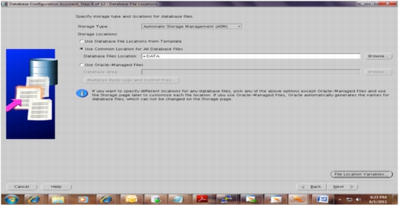
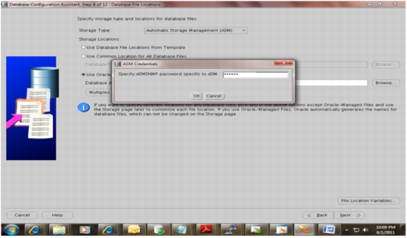
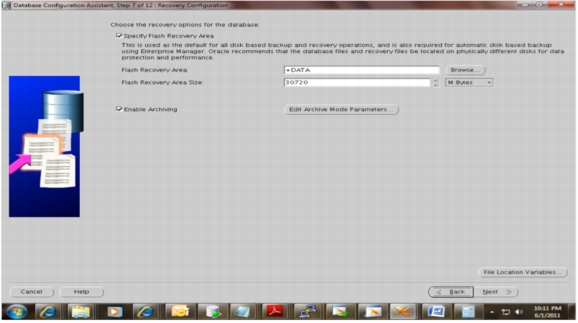
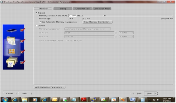
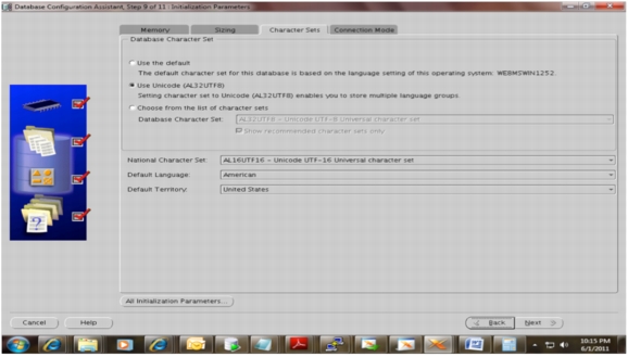
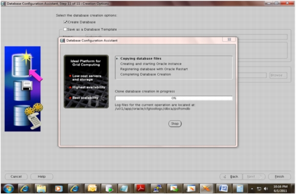
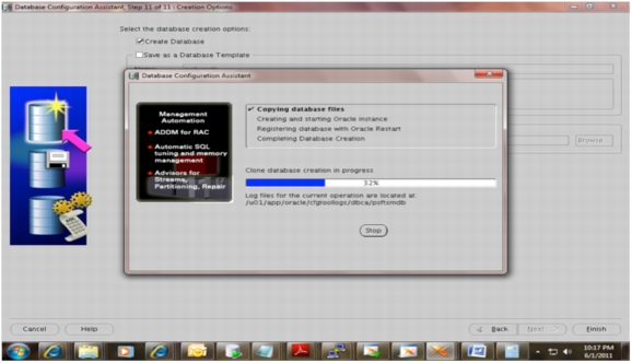
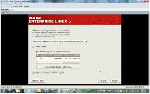
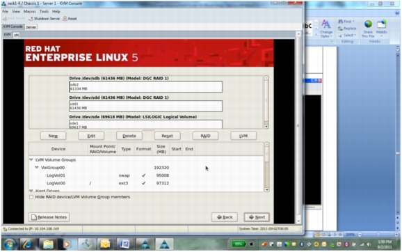
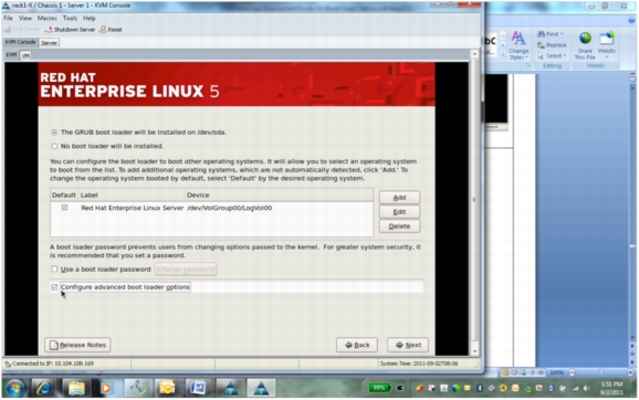
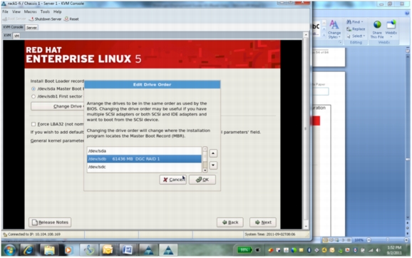
Log in as the oracle user and install the Oracle 11gr2 database server software as shown on the following screens. The screens and procedures cover the installation of both Oracle Automatic Storage Management (ASM) and Oracle server binaries.
Oracle ASM Installation
Database Binaries Installation
Oracle Tuxedo Installation on Database Server
Log in to the Oracle PeopleSoft database server box as psoft and follow the installation procedure shown here.
Note: Oracle Tuxedo installation was performed in console mode. The following listing shows the procedure captured during the Oracle Tuxedo installation on the database server.
[psoft@psft-app1 ~]$ cd /u01/softwares/Tuxedo10gR3-linux
InstallAnywhere will guide you through the Tuxedo 10gR3 installation.
It is strongly recommended that you quit all programs before continuing with this installation.
Enter "next' to proceed to the next screen. Enter "back" to modify the previous screen.
You may cancel this installation at any time by typing "quit".
WARNING: "Quitting" creates an incomplete Tuxedo 10gR3 installation. You must re-install Tuxedo 10gR3. For more information, see "Preparing to Install the
Oracle Tuxedo System" in the Tuxedo 10gR3 Installation Guide.
Congratulations. Tuxedo 10gR3 has been successfully installed to:
/u01/psoft/bea/tuxedo10gR3
PRESS <ENTER> TO EXIT THE INSTALLER:
Oracle Tuxedo Patch Installation on Database Server
Log in to the Oracle PeopleSoft database server as psoft and follow the installation procedure shown here.
Note: Oracle Tuxedo patch installation was performed in console mode. The following listing shows the procedure captured during the Oracle Tuxedo patch installation on the application server.
rpreleasenote = SUSE LINUX Enterprise Server 10 (x86_64) x86 for AMD64, 64bits Tuxedo
portreleasenotes= SUSE LINUX Enterprise Server 10 (x86_64) x86 for AMD64, 64bits Tuxedo
Installing server and client files...
Enter owner for patch files:
psoft
Enter group for patch files:
oinstall
The patch installation finished successfully.
Oracle PeopleTools 8.51 Installation on Database Server
Log in to the Oracle PeopleSoft database server as psoft and follow the installation procedure shown here.
Note: Oracle PeopleTools installation was performed in console mode. The following listing shows the procedure captured during the Oracle PeopleTools installation on the database server.
[psoft@psft-app1 ~]$ cd /u01/softwares/PT851-CDS/cd1/Disk1/InstData
Congratulations. PeopleTools has been successfully installed to:
/u01/psoft/pshome
PRESS <ENTER> TO EXIT THE INSTALLER:
Oracle PeopleTools 8.51.11 Patch Installation on Database Server
Log in to the Oracle PeopleSoft database server as psoft and follow the installation procedure shown here.
Note: Oracle PeopleTools patch installation was performed in console mode. The following listing shows the procedure captured during the Oracle PeopleTools patch installation on the database server.
[psoft@psft-app1 ~]$ cd /u01/softwares/85111-PATCH/cd85111/Disk1/InstData
Congratulations. PeopleTools has been successfully installed to:
/u01/psoft/pshome
PRESS <ENTER> TO EXIT THE INSTALLER:
Oracle PeopleSoft HRMS 9.1 Installation on Database Server
Log in to the Oracle PeopleSoft database server as psoft and follow the installation procedure shown here.
Note: Oracle PeopleSoft HRMS application installation was performed in console mode. The following listing shows the procedure captured during the Oracle PeopleSoft HRMS application installation on the database server.
[psoft@psft-app1 ~]$ cd /u01/softwares/HRMS91featurepack-dec2010/V23382-01/Disk1/InstData
[psoft@psft-app1 InstData]$ ls -ltr
-rwxrwxrwx 1 psoft oinstall 54824825 Nov 2 2010 setup.linux
-rwxrwxrwx 1 psoft oinstall 97750905 Nov 2 2010 setup.hp
-rwxrwxrwx 1 psoft oinstall 41059115 Nov 2 2010 setup.exe
-rwxrwxrwx 1 psoft oinstall 215945081 Nov 2 2010 setup.aix
-rwxrwxrwx 1 psoft oinstall 9637753 Nov 2 2010 setup.zlinux
-rwxrwxrwx 1 psoft oinstall 149426041 Nov 2 2010 setup.linux
-rwxrwxrwx 1 psoft oinstall 118656889 Nov 2 2010 setup.hp-ia64
-rwxrwxrwx 1 psoft oinstall 595646325 Nov 2 2010 sesource1.zip
-rwxrwxrwx 1 psoft oinstall 118 Nov 2 2010 MediaId.properties
Oracle Micro Focus Server Express 5.1wp4 Installation on Database Server
Log in to the database server as the root user.
Create a directory (if one does not exist) for installing Oracle Micro Focus Server Express 5.1 WP4: for example, Mkdir /u01/products/mf/svrexp-51_wp4-64bit.
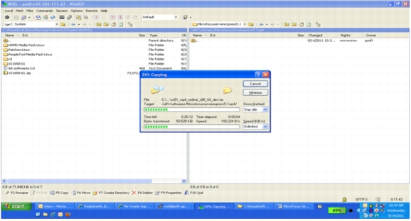
Transfer the downloaded software to the this folder. It is a tar file: sx51_wp4_redhat_x86_64_dev.tar.
WARNING: Any executables (whether a Run-Time System or an application)
must be relinked using this new release. Otherwise, the results of
running the older executables with this new release are undefined.
Installation completed successfully.
The COBOL system is ready to use.
Change the dot profile of the psoft user with the following values
COBDIR=/psft_app/products/mf/svrexp-51_wp4-64bit
export COBDIR
add /$COBDIR/lib to the LD_LIBRARY_PATH varaiable
add /$COBDIR/bin to the PATH variable
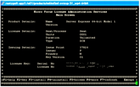
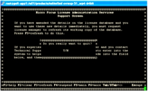
Install serial and license codes.
• Log in to the 10.104.111.67 server using Telnet from the command prompt. The user should be root.
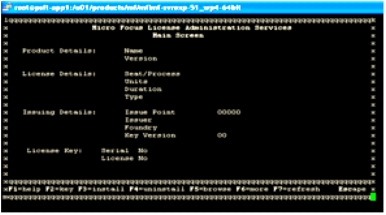
cd /u01/products/mf/mflmf-svrexp-51_wp4-64bit
./mflmadm
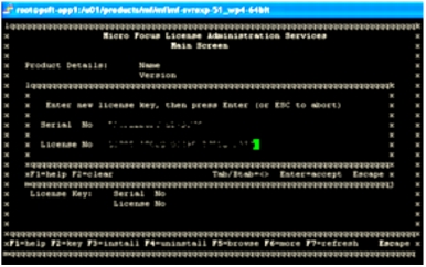
• Press F2 to enter the serial number and license key.
Press Enter to accept. Then screen appears as shown here.
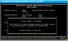
Press F3 key to install the license.
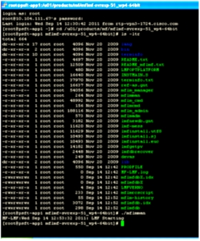
Open another session with the root user. Go to the directory /u01/products/mf/mflmf-svrexp-51_wp4-64bit. Run ./mflmman as shown on the following screen. The screen shows the license manager started.
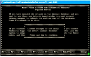
Return to the previous screen and press F3 to refresh the screen. The following screen appears.
Press the ESC key to exit
Select Y to leave the COBOL installation window.
Update the profile with the following variables
• Add the value /$COBDIR/bin to the PATH variable.
• Add the value /$COBDIR/lib to the LD_LIBRARY_PATH variable.
Compile the COBOL programs using ./pscbl.mak
• Go to $PS_HOME/setup.
• Run the command ./pscbl.mak. This command will compile all the COBOL programs and display a success message.
Linking the COBOL programs.
• Go to $PS_HOME/setup.
• Run the command ./psrun.mak. This command will link all the COBOL programs to the respective compiled files.
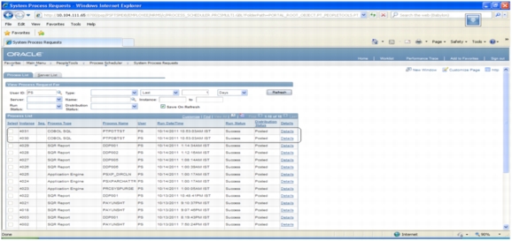
Log in to the Oracle PIA and run the sample COBOL processes. COBOL SQL processes should run successfully without any errors. The following screen shows running sample COBOL SQL processes.
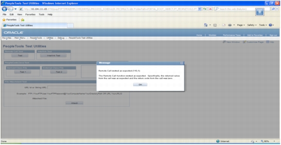
Test the remote call utility from Oracle PIA:
Choose Go to the PeopleTools > Utilities > Debug > PeopleTools Test Utilities.
Click Test.
Appendix D: Troubleshooting Common Installation Problems
Troubleshooting Oracle WebLogic Problems
If you have trouble with the installation of Oracle WebLogic, review these tips:
• You may need up to 800 MB of space to install Oracle WebLogic. If there is not enough space, the installer displays an error message with information about the space limitation. You will need to exit the installation process and create some space under your Home directory before restarting installation.
• The Oracle WebLogic installer uses the default system temporary space. It will stop and display an error message if the temporary space is not sufficient. Clean up the default system temporary space and try again. If you do not have the privileges needed to clean up that directory and need to proceed, as a workaround you can set aside a directory under your Home directory and use it as the temporary space. You can do this by setting -Djava.io.tmpdir in the command for launching the installer. For example, the following command will use the temp directory under your Home directory to launch the installer in console mode:
• If the installation fails, and if the directory that you specify for the Oracle WebLogic 10.3.2 installation is one in which other BEA products have been installed (BEA_HOME in previous releases; for example, c:\bea folder in Microsoft Windows), the registry.xml file in your existing BEA_HOME directory may be corrupted. Pick a different location to for the Oracle WebLogic 10.3.2 installation directory and try the installation again.
• If you are installing on the Microsoft Windows operating system using GUI mode and the installation fails without any message, run the installer from the command prompt using console mode. It will show you more detailed error messages indicating the problem area.
The command to run on Microsoft Windows in console mode is
• If you encounter the following error message while running in console mode on a Microsoft Windows operating system, it means that the environment variable _JAVA_OPTIONS has been set in your system. This setting causes the Java process initiated by the Oracle WebLogic installer to fail.
ERROR: JVMPI, an experimental interface, is no longer supported.
Please use the supported interface: the JVM Tool Interface (JVM TI).
To resolve the problem, remove the environment variable _JAVA_OPTIONS from your system and rerun the installation.
• If you encounter the following error message while installing on a Linux operating system, there is a problem with access to the temporary directory:
*sys-package-mgr*: cannot write cache file
This message appears because the Oracle WebLogic installer creates a temporary directory (for example, on Linux it is /var/tmp/wlstTemp) that is shared by all users and it is unable to differentiate between users.
As a result, access to the directory is blocked when the user accessing the directory is not the one who originally created the directory. The workaround for this problem is to remove the installation and install Oracle WebLogic again after manually adjusting the temporary directory permissions. A user with superuser privileges can use the following command to adjust the permissions:
• If you encounter the following error message while running Oracle PeopleSoft Pure Internet Architecture installed on a Microsoft Windows or Linux operating system and you are using Oracle JRockit R28 or later, you can ignore the error message and continue.
[WARN] -XXnoJITInline has no effect. Please update your command line.
If you prefer to avoid seeing the error message:
– Make a backup copy of the file <PS_HOME>/webserv/<domain_name>/bin/setEnv.cmd (sh).
– Open setEnv.cmd (sh) in a text editor and remove the JVM option -XXnoJITInline.
– Save the file.
Troubleshooting Application Server Problems
For troubleshooting help, you can access a log file through the Oracle PeopleSoft Domain Administration menu. Possible errors you may encounter are listed here:
• Use PSADMIN PeopleSoft Domain Administration menu option 6 for the Edit configuration and log files menu to check for errors in <PS_CFG_HOME>/appserv/<domain>/LOGS/APPSRV_mmdd.LOG and <PS_CFG_HOME>/appserv/<domain>/LOGS/TUXLOG.mmddyy.
• If an Oracle PeopleSoft server such as PSAPPSRV fails, examine your configuration parameters. The failure of the PSAPPSRV process is often signaled by the message "Assume failed," which means that the process has failed to start. Check the SIGNON section for a misspelled or invalid database name, an invalid or unauthorized OprId setting, or a missing or invalid ConnectId or ServerName setting. Also make sure that the database connectivity is set correctly.
• If a WSL (or JSL) fails to start, try specifying another port number (the port may be in use already by another application server domain process).
• If you are unable to start the bulletin board liaison (BBL) process, check that Oracle Tuxedo is installed fully and that the directory really exists.
• If the installation includes more than one application server domain on a single machine, before booting the second domain, adjust the REN server configuration in one of these ways to avoid conflict:
– Use PSADMIN to disable event notification (option 8 on the Quick Configure menu) for the second and subsequent application server domains.
– Change default_http_port to a value other than 7180.
Also check that you do not have older Oracle Tuxedo releases (such as Oracle Tuxedo 6.4) prepended in your PATH or runtime library (LIBPATH, SHLIB_PATH or LD_LIBRARY_PATH, depending on your UNIX platform).
Troubleshooting Database Installation Problems
If your script has stopped running midway through (this can happen for a number of reasons), you need to edit the script and start again.
To edit and restart the Data Mover Script (DMS):
• Identify the record that was being imported (that is, determine IMPORT command was running) when the script stopped.
Note: When building a DMO database or a multilingual database, the SET START statement can be difficult to add because DMS used to load the database includes more than one IMPORT statement. You need to view the log files to determine the IMPORT section of the script on which DMS failed. If the failure occurred during the first import operation, add the SET START statement before the first IMPORT *; statement. If the failure occurred during a subsequent import operation, comment out all preceding IMPORT *; statements and add the SET START statement before the IMPORT*; statement of the section in which the failure occurred. This step is very important. If you see any "unique index constraint" error messages in the Create Indexes step your IMPORT script failed during a subsequent import operation, but the SET START statement was added to the first IMPORT command. In this situation, you can run the DMS in its originally generated form, with only one modification: In the first IMPORT section, change the statement IMPORT *; to REPLACE_DATA *;. This change will delete all the data in the tables and reimport it. This process will take some time to run, and you will need to separately create each of the indexes that failed.
Add the following line before the offending IMPORT command (the one being run when the failure occurred):
Set start <RECORD NAME>;
where <RECORD NAME> is the name of the record that failed. Make sure to review the DMS log file to see where the script failed and locate the last record that was imported successfully. The SET START command will begin the DMS import at the record name specified.
Note: You should change the name of the log file in the script before each attempt at running it. This change helps ensure that you have a separate log file for each attempt if you run the import operation more than once.
Example
The script stops and a message similar to this one appears in the table:
Importing PSPNLFIELD
Rows inserted into PSPNLFIELD
3000
First drop the table in which rows have been partially inserted (for example, a record) by using the DROP TABLE command. Then restart the DMS at the record that failed using the SET START command and continue the DMS import operation. With Oracle PeopleSoft PeopleTools 8.4.0, this task can be accomplished in a single step.
Add the following lines before the offending IMPORT command (the one being run when the failure occurred):
SET START <RECORD NAME>;
DROP TABLE <RECORD NAME>;
where <RECORD NAME> is the name of the record that failed. Make sure to review the DMS log file to see where the script failed and locate the last record that was imported successfully. The SET START command will begin the DMS import operation at the record name specified, as shown in the following example.
Before
REM - PeopleTools System Database - US English
/
SET LOG ptengs.log;
SET INPUT ptengs.db;
SET COMMIT 30000;
SET NO VIEW;
SET NO SPACE;
SET NO TRACE;
SET UNICODE OFF;
IMPORT *;
After
REM - PeopleTools System Database - US English
/
SET LOG ptengs.log;
SET INPUT ptengs.db;
SET COMMIT 30000;
SET NO VIEW;
SET NO SPACE;
SET NO TRACE;
SET UNICODE OFF;
SET START PSPNLFIELD;
DROP TABLE PSPNLFIELD;
IMPORT *;
For the DROP statement, for records with a record name without a leading PS, add PS_ to the beginning of the record name; otherwise, the table will not be found.
ALL DESIGNS, SPECIFICATIONS, STATEMENTS, INFORMATION, AND RECOMMENDATIONS (COLLECTIVELY, "DESIGNS") IN THIS MANUAL ARE PRESENTED "AS IS," WITH ALL FAULTS. CISCO AND ITS SUPPLIERS DISCLAIM ALL WARRANTIES, INCLUDING, WITHOUT LIMITATION, THE WARRANTY OF MERCHANTABILITY, FITNESS FOR A PARTICULAR PURPOSE AND NONINFRINGEMENT OR ARISING FROM A COURSE OF DEALING, USAGE, OR TRADE PRACTICE. IN NO EVENT SHALL CISCO OR ITS SUPPLIERS BE LIABLE FOR ANY INDIRECT, SPECIAL, CONSEQUENTIAL, OR INCIDENTAL DAMAGES, INCLUDING, WITHOUT LIMITATION, LOST PROFITS OR LOSS OR DAMAGE TO DATA ARISING OUT OF THE USE OR INABILITY TO USE THE DESIGNS, EVEN IF CISCO OR ITS SUPPLIERS HAVE BEEN ADVISED OF THE POSSIBILITY OF SUCH DAMAGES.
THE DESIGNS ARE SUBJECT TO CHANGE WITHOUT NOTICE. USERS ARE SOLELY RESPONSIBLE FOR THEIR APPLICATION OF THE DESIGNS. THE DESIGNS DO NOT CONSTITUTE THE TECHNICAL OR OTHER PROFESSIONAL ADVICE OF CISCO, ITS SUPPLIERS OR PARTNERS. USERS SHOULD CONSULT THEIR OWN TECHNICAL ADVISORS BEFORE IMPLEMENTING THE DESIGNS. RESULTS MAY VARY DEPENDING ON FACTORS NOT TESTED BY CISCO.
CCDE, CCENT, Cisco Eos, Cisco Lumin, Cisco Nexus, Cisco StadiumVision, Cisco TelePresence, Cisco WebEx, the Cisco logo, DCE, and Welcome to the Human Network are trademarks; Changing the Way We Work, Live, Play, and Learn and Cisco Store are service marks; and Access Registrar, Aironet, AsyncOS, Bringing the Meeting To You, Catalyst, CCDA, CCDP, CCIE, CCIP, CCNA, CCNP, CCSP, CCVP, Cisco, the Cisco Certified Internetwork Expert logo, Cisco IOS, Cisco Press, Cisco Systems, Cisco Systems Capital, the Cisco Systems logo, Cisco Unity, Collaboration Without Limitation, EtherFast, EtherSwitch, Event Center, Fast Step, Follow Me Browsing, FormShare, GigaDrive, HomeLink, Internet Quotient, IOS, iPhone, iQuick Study, IronPort, the IronPort logo, LightStream, Linksys, MediaTone, MeetingPlace, MeetingPlace Chime Sound, MGX, Networkers, Networking Academy, Network Registrar, PCNow, PIX, PowerPanels, ProConnect, ScriptShare, SenderBase, SMARTnet, Spectrum Expert, StackWise, The Fastest Way to Increase Your Internet Quotient, TransPath, WebEx, and the WebEx logo are registered trademarks of Cisco Systems, Inc. and/or its affiliates in the United States and certain other countries.