The NCS 2000 evolves the Cisco ROADM portfolio by introducing Cisco nLight ROADM technology. By supporting touchless reconfigurability through colorless, omnidirectional, and contentionless add/drop, networks built upon nLight ROADM can instantly respond to new bandwidth requests, route around network failures, and dynamically adjust their topology - all without manual intervention.
16-port Flex Spectrum ROADM Line Card
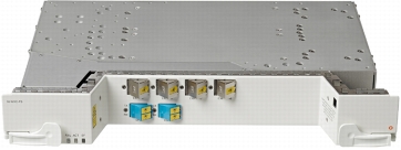
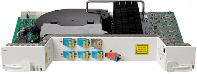
The Cisco 16-port Flex Spectrum ROADM Line Card (16-WXC-FS) is a double-slot unit that provides multidegree switching capabilities not only at the individual wavelength level but also with flexible spectrum allocations. You can use the 16-port Flex Spectrum ROADM Line Card in the core of the network to build ROADM nodes with 96 channels spaced at 50-GHz, FlexSpectrum channels, or a combination of the two. By using a simple software reconfiguration, the same unit can provide colorless multiplexing and demultiplexing to ROADM nodes.
Figure 1. Cisco 16-port Flex Spectrum ROADM Line Card
Features and Benefits
The 16-port Flex Spectrum ROADM Line Card creates an agile DWDM layer forming the foundation for converged transport architectures, delivering many features and innovations that enable significant provisioning and recovery flexibility. Wavelength routing, including direction and frequency changes, are entirely software-driven, easing one of the major contributors to high operating expenses (OpEx) and long provisioning and recovery delays caused by manual operator intervention.
Agile DWDM innovations and benefits supported by the 16-port Flex Spectrum ROADM Line Card include:
• Colorless add/drop ports: In previous generations of ROADM technology, add/drop ports were assigned to a fixed frequency, requiring the frequency of the transmitter to align to that of the add/drop port. Colorless ROADM ports are not frequency-specific. Therefore, in addition to simplifying provisioning, a re-tuned laser does not require a fiber move, allowing the transmitter wavelength to be selected in software, with no manual intervention required.
• Omni-directional add/drop ports: Unlike traditional ROADMs in which an add/drop port is associated with a single, fixed egress direction, omnidirectional ROADM ports are not direction-specific. A wavelength reroute does not require a physical fiber move, and can therefore be executed entirely by software.
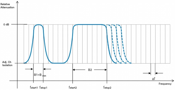
• FlexSpectrum: The amount of spectrum allocated to a given wavelength can be flexibly provisioned to allow for growth to 400-gigabit or even 1-terabit bandwidths. The term "FlexSpectrum" indicates the capability of the 16-port Flex Spectrum ROADM Line Card to manage an arbitrary set of continuous portions (or frequency slices) of the optical spectrum, delimited by programmable "start" and "stop" frequencies, as described in Figure 2.
Figure 2. The FlexSpectrum Concept
• High reliability: The 16-port Flex Spectrum ROADM Line Card node architecture enables complete independence between the direction-facing units, including the ability to house units in physically separated shelves.
• Flexibility: The 16-WXC can work either as a core building block of a ROADM node or as a colorless multiplexer/demultiplexer. Consequently, you can use 16-port Flex Spectrum ROADM Line Card ports to manage individual channels (multiplexer/demultiplexer operation) or to terminate optical multiplex sections, allowing network/ring interconnection without optical-electrical-optical (OEO) conversion.
Product Description
The 16-port Flex Spectrum ROADM Line Card is a 2-slot unit that you can insert into slots 2, 4, or 6 of the NCS 2006 chassis. The unit has 36 input/output fibers among the following connectors:
• Two LC-duplex adapters for COM and UPG ports
• Four MPO connectors for ADD, DROP, and EXP ports
The 16-port Flex Spectrum ROADM Line Card incorporates faceplate-mounted LEDs to provide a quick visual check of the operational status of the card. Printed on each of the faceplates is an icon (an orange circle), which is mapped to shelf-slot icons that indicate the shelf-slot where you can physically install the card. The cards are supported by the integrated Cisco Transport Controller craft manager, which provides the user access to system operations, administration, maintenance, and provisioning (OAM&P). Cisco Transport Controller can also provide a per-channel graphical representation of the optical power levels associated with each path in the ROADM node.
Figure 3 shows the internal layout of the 16-port Flex Spectrum ROADM Line Card, and Figure 4 shows an n-degree ROADM layout where the 16-port Flex Spectrum ROADM Line Card associated with each degree of the node offers a total of 16 ports (plus one upgrade port), which can be connected either toward other directions or toward the local add/drop section.
Figure 3. 16-port Flex Spectrum ROADM Line Card Unit Layout
The Cisco NCS 2000 features a new generation of passive modules to accommodate ROADM nodes built with the 16-port Flex Spectrum ROADM Line Card. Three types of modules are available - patch-panel modules, add/drop modules, and adapter modules - all of which fit into four slots of a 1-rack-unit (1RU) mechanical frame chassis (MF-1RU) (Figure 5). Their passive nature helps ensure extremely high availability in a small, low-power footprint.
Figure 5. Mechanical Frame Chassis
Modular Patch Panel Modules
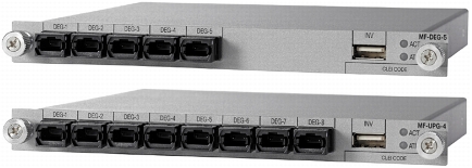
ROADM node architectures built with the 16-WXC feature a modular approach to degree interconnection, offering a pay-as-you-grow model consisting of a combination of just two units: a 5-Degree Patch Panel Module (MF-DEG-5) and a 4-Degree Upgrade Patch Panel Module (MF-UPG-4) (Figure 6).
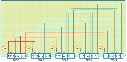
The 5-Degree Patch Panel Module (MF-DEG-5) provides interconnections between five 8-port MPO connectors; it is used to connect any combination of up to five ROADM line degrees (express connections) and add/drop components (add/drop connections). The 40 optical paths are interconnected as shown in Figure 7. Five photodiodes provide power monitoring of fiber 1 of each MPO connector. Power values as well as the manufacturing data stored in the flash memory are provided to Cisco Transport Controller through the USB connection. This module is single-slot height in the mechanical frame chassis.
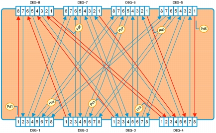
The Cisco 4-Degree Upgrade Modular Patch Panel Module (MF-UPG-4) provides interconnections among eight 8-fiber MPO connectors; it is used to expand the number of degrees and the number of add/drop ports supported by the node. The 64 optical paths are interconnected as shown in Figure 8. A total of eight photodiodes provide power monitoring of fiber 1 of each MPO connector. Power values as well as the manufacturing data stored in the flash memory are provided to Cisco Transport Controller through the USB connection. This module is single-slot height in the mechanical frame chassis.
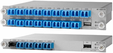
A set of add/drop modules provides colorless, omnidirectional, and FlexSpectrum add/drop functions to 16-port Flex Spectrum ROADM Line Card -based ROADM nodes. Two different add/drop modules are available: the Cisco 1 x 16 Colorless FlexSpectrum Add/Drop Module and the Cisco 4 x 4 Colorless Omnidirectional FlexSpectrum Add/Drop Module (Figure 9).
Figure 9. Cisco 1 x 16 CFS Add/Drop and 4 x 4 Colorless Omnidirectional FlexSpectrum Add/Drop Modules
1 x 16 Colorless FlexSpectrum Add/Drop Module
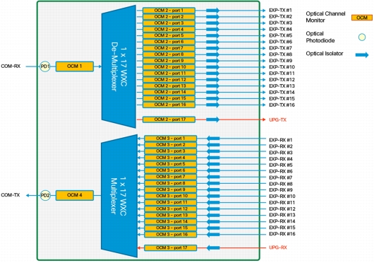
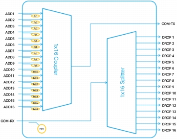
The Cisco 1 x 16 Colorless FlexSpectrum Add/Drop Module (16AD-CFS) is a passive unit comprising one 1 x 16 splitter and one 16 x 1 combiner, plus 17 photodiodes arranged as shown in Figure 10. This module is double-slot height (full height) in the mechanical frame chassis. Its primary function is to provide optical multiplexing and demultiplexing for up to 16 optical signals. Because it is based on optical splitter and combiner technology, only transceivers employing coherent detection can be directly connected to the 16 client ports of the unit. Integrated photodiodes provide connectivity check and monitoring functions. Virtual photodiodes are implemented on the drop ports by subtracting the insertion losses from the photodiode reading on the COM-RX port. Power values as well as the manufacturing data stored in the flash memory are provided to Cisco Transport Controller through the USB connection.
Figure 10. Cisco 1 x 16 Colorless FlexSpectrum Add/Drop Module
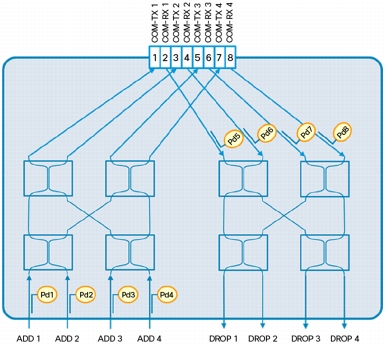
The Cisco 4 x 4 Colorless Omnidirectional FlexSpectrum Add/Drop Module (4X4-COFS-AD) is a passive unit consisting of eight 2 x 2 optical couplers and eight photodiodes, arranged as shown in Figure 11. This module is single-slot height in the mechanical frame chassis. Power monitoring is present at each channel input port and at each common input port. Virtual photodiodes are implemented on the channel drop ports by subtracting the insertion losses from the photodiode reading on the COM-RX ports. Power values as well as the manufacturing data stored in the flash memory are provided to Cisco Transport Controller through the USB connection. Its primary function is to provide optical multiplexing and demultiplexing for up to four optical signals. Because it is based on optical splitter and combiner technology, only transceivers employing coherent detection can be directly connected to 4 client ports of this unit.
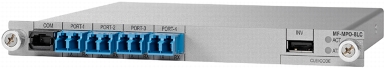
The Cisco MPO-8xLC Adapter Module provides mechanical adaptation from units offering LC connections to those with MPO connectors, such as the 16-WXC-FS (Figure 12).
Figure 12. Cisco MPO-8xLC Adapter Module
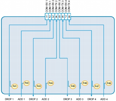
A total of eight photodiodes provide power monitoring of channel input and output port, as shown in Figure 13.
Figure 13. Cisco MPO-8LC Optical Block Diagram
Features and Benefits
The ROADM node architecture has been specifically defined and engineered to provide:
• High reliability: The modular architecture enables complete independence between specific direction-facing units with the ability to house units in physically separated shelves.
• Low insertion loss: Selected technology allows direct integration of different functions in the same optical module, reducing to a minimum the number of optical connections.
• Reduced footprint: The auxiliary passive units integrate power monitoring with a minimum footprint, reducing node power consumption and increasing system density.
Each module is connected via USB with the External Connection Unit (ECU) of the NCS 2006 chassis. The USB communication channel is used to:
• Retrieve the data stored in the nonvolatile memory of the module, specifically inventory data and the insertion loss of the optical paths
• Retrieve the optical power levels monitored by the photodiode of the module
• Activate an LED indicator on the front panel of each module
Next-Generation Amplification
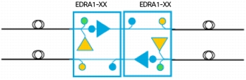
The Cisco NCS 2000 introduces hybrid Raman-EDFA amplifiers known as erbium doped Raman amplifiers, or EDRAs. EDRAs are compact and easy to deploy, and they support an ultra-low noise figure critical for long-distance, high-bit-rate transmission. Supporting 96 channels in the C-band, Cisco NCS 2000 Erbium Doped Raman Amplifiers are plug-in modules that provide the reach and optical performance required to meet the most demanding distance requirements of service provider and enterprise DWDM networks (Figure 14).
Raman amplifiers employ the intrinsic properties of silica fiber to obtain signal amplification such that the transmission fibers themselves are used as a medium for amplification, allowing the attenuation of data signals transmitted over the fiber to be mitigated within the fiber itself. An amplifier working on the basis of this principle is commonly known as a distributed Raman amplifier (DRA) or simply a Raman amplifier.
The card has four versions:
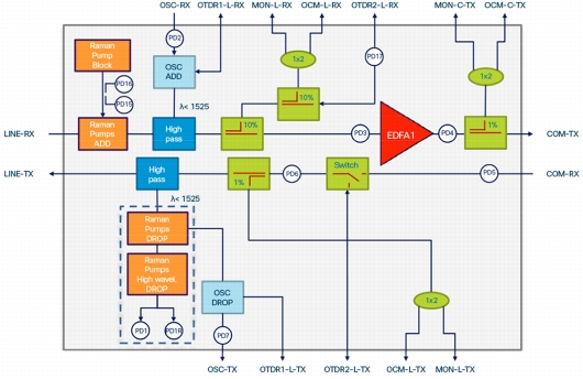
• EDRA1-26 includes an erbium doped pre-amplifier, EDFA1, with a nominal gain of 14 dB. It supports a maximum span of 26 dB on standard single-mode fiber (Figure 15).
• EDRA1-35 includes an erbium doped pre-amplifier, EDFA1, with a nominal gain of 21 dB. It supports a maximum span of 35 dB on standard single-mode fiber (Figure 15).
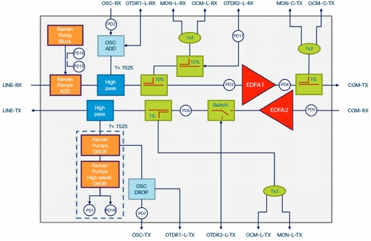
• EDRA2-26 includes an erbium doped pre-amplifier, EDFA1, and an erbium doped booster amplifier, EDFA2, where EDFA1 has a nominal gain of 14 dB. It supports a maximum span of 26-dB on standard single-mode fiber (Figure 16).
• EDRA2-35 includes an erbium doped pre-amplifier, EDFA1, and an erbium doped booster amplifier, EDFA2, where EDFA1 has a nominal gain of 21 dB. It supports a maximum span of 35 dB on standard single-mode fiber (Figure 16).
Each EDRA card can manage (on each port) up to 96 channels, 50-GHz-spaced from 196.1 GHz (1528.77nm) to 191.35 GHz (1566.72 nm). The optical channel monitor (OCM) ports are used to read the per-channel power level continuously from all optical ports using an external OCM card. The optical time domain reflectometry (OTDR) ports are used to perform OTDR measurements using an external OTDR card.
Features and Benefits
Each EDRA performs the following functions:
• Amplifies the ingress line signal through a true variable gain EDFA (EDFA1) without midstage access
• Amplifies the egress line signal through a true variable gain EDFA (EDFA2) in EDRA-2 amplifiers
• Provides a 1-watt counter-propagating Raman pump
• Provides optical service channel (OSC) add/drop and the ability to perform OTDR, chromatic dispersion (CD), and OCM functions using an external card
Figure 15. EDRA-1 Block Diagram
Figure 16. EDRA-2 Block Diagram
Each integrated optical amplifier provides the following features:
• Embedded gain flattening filter
• Constant pump current mode (test mode)
• Constant output power mode
• Constant gain mode
• Nondistorting low-frequency transfer function
• Amplified spontaneous emission (ASE) compensation in constant gain and in constant output power mode
• Fast transient suppression
• Programmable tilt
• Hardware-based optical safety functions through signal loss detection and alarm at any input port, fast power-down control, and reduced maximum output power in safe power mode
• Hardware limit to support system safety Class 1M at any optical port
The Raman pump provides the following features (Figure 17):
• Total pump power of 1000 mW, consisting of four pumps over four wavelengths
• Raman pump back-reflection detector to detect the amount of Raman pump power back-scattered by the LINE-RX connector and by the transmission fiber
• Remnant Raman pump detection at the end of the counter-pumped span
• Hardware-based optical safety functions through signal-loss detection and alarm at any input port, fast power-down control, and reduced maximum output power in safe power mode
• Hardware limit to support system safety Class 1M at LINE-RX
Figure 17. Raman Pump Block Diagram
Other features applicable to EDRA cards follow:
• OCM and OTDR ports for measurements through an external card; a switch is used for OTDR and CD measurements to add external signal on LINE-TX section; the switch is also used on EDRA1-XX for optical safety purposes (automatic laser shutdown of C-band signals on LINE-TX)
• Full monitoring and alarm handling capability of Raman pump, EDFAs, and signal power
• Non-traffic-affecting firmware upgrade
• High reliability, which enables complete independence between specific direction-facing units with the ability to house units in physically separate shelves
Product Description
The EDRA cards are 2-slot units that can be inserted into slots 2, 4, or 6 of the NCS 2006 chassis. The unit has 16 input/output fibers among the following connectors:
• Eight LC-UPC/2 connectors
• One high-power connector E-2000 PS PC (0°)
• One MPO 8-fiber connector for OCM, CD, and OTDR functions
EDRA units incorporate faceplate-mounted LEDs to provide a quick visual check of the operational status of the card. Printed on each of the faceplates is an icon (an orange circle), which is mapped to shelf-slot icons that indicate the shelf slot where you can physically install the card. The cards are supported by the integrated Cisco Transport Controller craft manager, which gives you access to system OAM&P.
You can use the units in optical line amplification (OLA) nodes (Figure 18), in ROADM nodes (Figure 19), and in dynamic gain equalizer (DGE) sites in combination with 16-port Flex Spectrum ROADM Line Card units (Figure 20).
Figure 18. OLA Node Layout
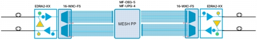
Figure 19. ROADM Node Layout
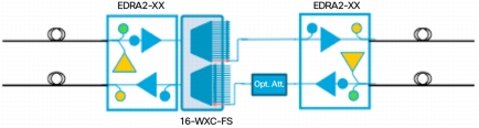
Figure 20. DGE Node Layout
In OLA nodes, EDRAs can work with other EDRAs, with Cisco ONS 15454 MSTP OPT-EDFA-17 and OPT-EDFA-24 amplifiers, or with Cisco ONS 15454 MSTP High-Power Counter-Propagating and Co-Propagating Raman Amplifiers.
16-port Flex Spectrum ROADM Line Card Product Specifications
Tables 1 and 2 list the optical and physical specifications, respectively, for the 16-port Flex Spectrum ROADM Line Card.
Table 1. Optical Specifications
Parameter
Condition
Value
Channel grid
96 channels, 50 GHz-spaced ITU grid
Central wavelength - Channel 1
191.350 THz (1566.72 nm)
Central wavelength - Channel 96
196.100 THz (1528.77 nm)
FlexSpectrum "slice" width
12.5 GHz
Minimum settable channel bandwidth
50 GHz - 4 slices
Maximum settable "super-channel" bandwidth
500 GHz - 40 slices
Total number of slices
384 slices - 4800 GHz
f_start of first slice
191'325 GHz
Insertion loss
Minimum 4 dB, maximum 8 dB
Optical port isolation
COM <-> EXP path; all SOP, within entire operating temperature range and within OWB
(H x W x D): 0.67 x 7.05 x 6.5 in. (16.9926 x 178.9938 x 164.9984 mm) for DEG-5, UPG-4, MPO-8LC, and 4x4 COFS-AD
1.39 x 7.05 x 6.50 in. (35.2044 x 178.9938 x 164.9984 mm) for 16AD-CFS
Weight
1.28 lb (0.58 kg) for DEG-5, UPG-4, MPO-8LC, and 4x4 COFS-AD
1.76 lb (0.8 kg) for 16AD-CFS
MTBF (predicted)
NCS2K -MF-16AD-CFS 5,422,405
NCS2K -MF-4X4-COFS 21,739,130
NCS2K -MF-MPO-8LC 49,019,607
NCS2K-MF-DEG-5 35,087,719
NCS2K -MF-UPG-4 50,000,000
Management
Card LEDs
Each module has two LEDs at front panel: one blue LED and one three-color LED (yellow, green, and red). Both LEDs can also blink at 0.5 Hz and 2.5 Hz on request.
The LED is used to:
• Notify that the module is powered but not associated. LED not blinking, color yellow
• Notify that the module is powered and associated. LED not blinking, color green
• Help operator identify a specific module, light-up blue LED (blinking)
Operating Environment
Temperature
23 to 131°F (-5 to 55°C)
Relative humidity
5 to 95%
Table 11. ROADM Passive Auxiliary Modules Ordering Information
Product Name
Description
NCS2K-MF-1RU=
Mechanical Frame - 4 slots - 1 RU
NCS2K-MF-DEG-5=
Mesh Interconnection MF Unit - Up to 5 Degrees
NCS2K-MF-UPG-4=
Mesh Interconnection MF Unit - Upgrade - 4 Degrees
NCS2K-MF-16AD-CFS=
16-Ports Add/Drop MF Unit - Colorless and FlexSpectrum
NCS2K-MF-4X4-COFS=
4-Degree and 4-Ports Add/Drop MF Unit - CO and FlexSpectrum
NCS2K-MF-MPO-8LC=
MPO to 8x LC Fan-Out MF Unit - With Integrated Monitoring
EDRA Product Specifications
Tables 12 and 13 give optical specifications for the Raman and EDFA sections of the amplifiers and Table 14 gives physical specifications.
Table 12. Optical Specifications for Raman Section
Parameter
Condition
Minimum
Typical
Maximum
Units
Pump 1 wavelength
1423
nm
Pump 2 wavelength
1434
nm
Pump 3 wavelength
1455
nm
Pump 4 wavelength
1470
nm
Pump spectral width
± 1
± 3
nm
Operating range of Raman pump power
100
1000
mW
Raman pump unit class at operative power
With system optical safety single hardware failure included (worst-case fault)
1M
-
Table 13. Optical Specifications for EDFA Section
Parameter
Unit Type
Condition
Minimum
Typical
Maximum
Unit
Operative input power range
EDRA1-26
EDRA2-26
Full channel load with maximum value of signal output power
6
16
dBm
Single channel with minimum value of signal output power
-22
-12
dBm
EDRA1-35
EDRA2-35
Full channel load with maximum value of signal output power
-1
14
dBm
Single channel with minimum value of signal output power
-29
-14
dBm
EDFA1 class
Single hardware failure included (worst-case fault)
1M
Signal output power range
Full channel load
23.2
dBm
Single channel
20.2
dBm
Standard gain range
EDRA1-26
EDRA2-26
EDRA1-35
EDRA2-35
Output gain tilt = 0 dB
23
dBm
Single channel
-5
dBm
Extended gain range
EDRA1-26
EDRA2-26
EDRA1-35
EDRA2-35
Output gain tilt ≠ 0
7
14
dB
Single channel
9
21
dBm
Table 14. EDRA Physical Specifications
Parameter
Value
Power
150W maximum
Size
2 slots, (H x W x D): 13.1 x, 1.93 x 9.84 in. (33.27 x 4.90 x 24.99 cm)
• ETS 300-019-2-1 V2.1.2 (2000-09) (Storage, Class 1.1)
• ETS 300-019-2-2 V2.2.1 (2011-11): Transportation, Class 2.3
• ETS 300-019-2-3 V2.2.2 (2003-04): stationary use, Class 3.1E
Table 17. System Requirements
Component
Cisco ONS 15454
Cisco NCS 2006
Processor
TNC/TSC/TNC-E/TSC-E
TNC-E/TSC-E
Shelf assembly
15454-M6-SA shelf assembly
NCS2006-SA shelf assembly
System software
Release 10.0 NCS Software
Release 10.0 NCS Software
Warranty
The following warranty terms apply to the Cisco NCS 2006 as well as services you may use during the warranty period. Your formal warranty statement appears in the Cisco Information Packet that accompanies your Cisco product.
• Hardware warranty duration: Five years.
• Software warranty duration: One year.
• Hardware replacement, repair, or refund procedure: Cisco or our service center will use commercially reasonable efforts to ship a replacement part for delivery within 15 working days after receipt of the defective product at Cisco's site. Actual delivery times of replacement products may vary depending on customer location.
Cisco Services for Migrating Converged IP+Optical Solutions
Services from Cisco and our partners help you get the most value from your investments in Cisco's converged IP+Optical solution, quickly and cost effectively. We can help you design, implement, and validate your solution to speed migration and cutover. Coordinate every step through to interworking. Strengthen your team. And make the most of tomorrow's opportunities. Learn more at http://www.cisco.com/go/spservices.