Document ID: 12225
Updated: Mar 04, 2008


Contents
Introduction
This document describes the X.21 cable assembly and pinouts (Data Terminal Equipment - DTE and Data Communications - DCE).
Prerequisites
Requirements
There are no specific requirements for this document.
Components Used
This document is not restricted to specific software and hardware versions.
The information in this document was created from the devices in a specific lab environment. All of the devices used in this document started with a cleared (default) configuration. If your network is live, make sure that you understand the potential impact of any command.
Conventions
Refer to Cisco Technical Tips Conventions for more information on document conventions.
X.21 Cable Assembly
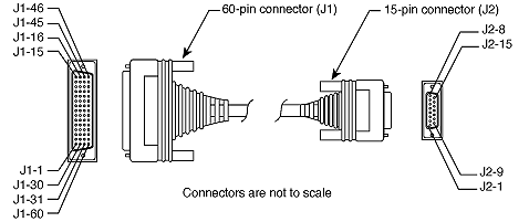
X.21 DTE Cable Pinouts (DB-60 to DB-15)
The arrows in this table indicate signal direction:
-
--> indicates DTE to DCE
-
<-- indicates DCE to DTE
-
-- means direction not applicable
| 60 Pin*1* | Signal | Description | Direction | 15 Pin | Signal |
|---|---|---|---|---|---|
| J1-48 J1-47 | GND MODE_2 | Shorting Group | -- | -- | -- |
| J1-51 J1-52 | GND MODE_DCE | Shorting Group | -- | -- | -- |
| J1-46 | Shield_GND -- | Single | -- | J2-1 | Shield GND |
| J1-11 J1-12 | TxD/RxD+ TxD/RxD-- | Twisted pair no. 3 | --> --> | J2-2 J2-9 | Transmit+ Transmit-- |
| J1-9 J1-10 | RTS/CTS+ RTS/CTS-- | Twisted pair no. 2 | --> --> | J2-3 J2-10 | Control+ Control-- |
| J1-28 J1-27 | RxD/TxD+ RxD/TxD-- | Twisted pair no. 6 | <-- <-- | J2-4 J2-11 | Receive+ Receive-- |
| J1-1 J1-2 | CTS/RTS+ CTS/RTS-- | Twisted pair no. 1 | <-- <-- | J2-5 J2-12 | Indication+ Indication-- |
| J1-26 J1-25 | RxC/TxCE+ RxC/TxCE-- | Twisted pair no. 5 | <-- <-- | J2-6 J2-13 | Timing+ Timing-- |
| J1-15 Shield | Control_GND -- | Twisted pair no. 4 | -- -- | J2-8 Shield | Control GND -- |
| *1* Any pin not referenced is not connected. | |||||
X.21 DCE Cable Pinouts (DB-60 to DB-15)
| 60 Pin*1* | Signal | Description | Direction | 15 Pin | Signal |
|---|---|---|---|---|---|
| J1-48 J1-47 | GND MODE_2 | Shorting Group | -- | -- | -- |
| J1-46 | Shield_GND | Single | -- | -- | -- |
| J1-46 | Shield_GND -- | Single | -- | J2-1 | Shield GND |
| J1-28 J1-27 | RxD/TxD+ RxD/TxD-- | Twisted pair no. 6 | <-- <-- | J2-2 J2-9 | Transmit+ Transmit-- |
| J1-1 J1-2 | CTS/RTS+ CTS/RTS-- | Twisted pair no. 1 | <-- <-- | J2-3 J2-10 | Control+ Control-- |
| J1-11 J1-12 | TxD/RxD+ TxD/RxD-- | Twisted pair no. 3 | --> --> | J2-4 J2-11 | Receive+ Receive-- |
| J1-9 J1-10 | RTS/CTS+ RTS/CTS-- | Twisted pair no. 2 | --> --> | J2-5 J2-12 | Indication+ Indication-- |
| J1-24 J1-23 | TxC/RxC+ TxC/RxC-- | Twisted pair no. 4 | --> --> | J2-6 J2-13 | Timing+ Timing-- |
| J1-15 Shield | Control_GND -- | Twisted pair no. 5 | -- -- | J2-8 Shield | Control GND -- |
| *1* Any pin not referenced is not connected. | |||||
Related Information
Open a Support Case  (Requires a Cisco Service Contract.)
Related Cisco Support Community Discussions
The Cisco Support Community is a forum for you to ask and answer questions, share suggestions, and collaborate with your peers.
Refer to Cisco Technical Tips Conventions for information on conventions used in this document.