Cisco Connected Mobile Experience Browser Engage Overview
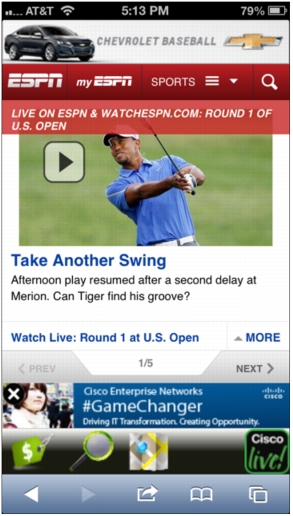
Cisco® Connected Mobile Experience (CMX) Browser Engage enables enterprises to use their offered network access (usually wireless) as a strategic revenue-generating tool. It enables the enterprise to place a context-relevant banner on the web browsers of endusers' wireless or wired devices while they are visiting an HTTP webpage.
Enterprises can use this web banner insertion to interact with their customers and provide them with services, guidance, and offers (Figure 1). This solution both provides a better experience for endusers (who can now easily find relevant information about the services around them, including locations and maps) and enables enterprises to monetize the web banner through the use of relevant advertisements and collect valuable analytical data about their customers' surfing behavior while on the enterprise network.
Figure 1. Enterprises Can Use Web Banners to Interact with Customers
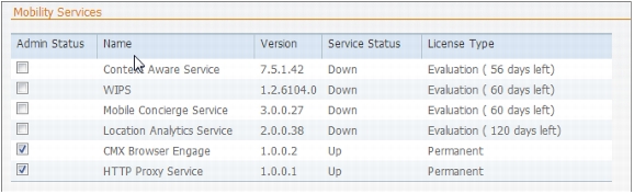
Starting with Cisco Mobility Services Engine (MSE) Software Release 7.5, CMX Browser Engage will be available as a service on Cisco MSE. CMX Browser Engage is licensed as an advanced location service. Thus, in addition to Context Aware Service (CAS), Wireless Intrusion Prevention System (wIPS), Mobile Concierge, and Location Analytics Service, CMX Browser Engage and the accompanying HTTP Proxy Service will be available as a new service.
CMX Browser Engage is the business user interface to the back-end configuration system for advertisement intelligence and information. It consists of two components:
• Cisco CMX dashboard: The dashboard resides on Cisco MSE and is used to manage Cisco CMX campaigns. It should be run on a separate Cisco MSE (if using a low-end Cisco 3355 MSE or a standard Cisco MSE Virtual Appliance [VMSE]) or on ahigh-end Cisco MSE with other services. For best performance, you should host the Cisco CMX dashboard on a separate Cisco MSE.
• HTTP Proxy Service: The HTTP Proxy Service can reside on either Cisco MSE (for a central switched environment; the low-end Cisco 3355 MSE and the standard Cisco VMSE are supported) or a Cisco Integrated Services Router Generation 2 (ISRG2) running a Cisco UCS® E-Series Server (for Cisco Flex local deployments). A high-end Cisco VMSE cannot be used for Cisco MSE HTTP Proxy Service. HTTP Proxy Service is the proxy service that receives the redirected end-user HTTP requests, terminating the TCP stack and inserting the banners and additional Java script in the returning HTTP page.
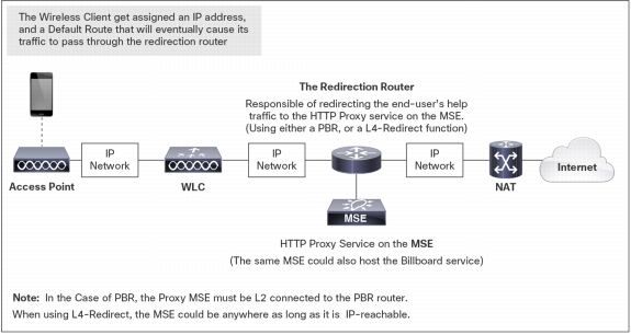
In addition to the CMX Browser Engage services running on Cisco MSE, another crucial component is a redirection router (for central deployments using Cisco MSE as a proxy). The router sits in the data path of the enduser's traffic to the Internet and is responsible for intercepting and redirecting the enduser's HTTP traffic to the Cisco MSE HTTP Proxy Service. This redirection can be implemented through policy-based routing (PBR) or through the Layer 4 Redirect function available on higher-end routers (such as the Cisco ASR 1000 Series Aggregation Services Routers with Cisco Intelligent Services Gateway [ISG]). Figure 2 shows the redirection router.
Figure 2. Cisco MSE with Redirection Router
Note: The end-user device need to be on a different subnet than the HTTP Proxy Service for proper operation.
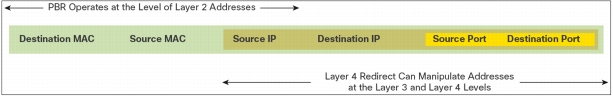
Each redirection method (PBR and Layer 4 Redirect) has its ideal placement according to the requirements of the deployment. PBR alters only the destination MAC address of an Ethernet frame, but Layer 4 Redirect can alter both the destination IP address (making the destination the proxy server) and the destination port number (for example, it can change the HTTP destination port 80 to port 9090: the default port for the CMX Browser Engage HTTP Proxy Service). Figure 3 shows the two methods.
Figure 3. PBR and Layer 4 Redirect
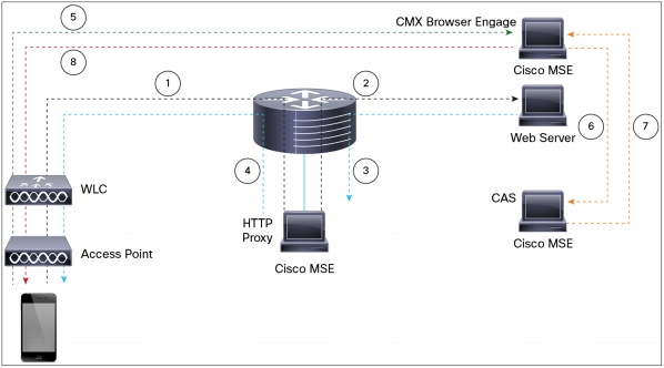
Figure 4 shows the HTTP flow step by step as it is initiated from a wireless client and the interactions through the various components providing the CMX Browser Engage service.
Figure 4. CMX Browser Engage Service Flow
1. Client browser makes HTTP request to the server. It is intercepted by the router using PBR/L4R and forwarded to the proxy service.
2. The proxy terminates the connection and opens another connection to the web server. It proxy the client request.
3. Web server response. The proxy transforms the html response by inserting a script tag with BBX server IP and client IP. (The Proxy needs to know the BBX server IP)
4. Proxy responds to the client with transformed html payload.
5. Client browser interprets the script tag and makes a request to the BBX server communicating the Client IP.
6. BBX server requests client location from the CAS server.
7. CAS server responds with the client location.
8. BBX serves the advertisement to the client using the location information and Campaign configuration.
The simplest deployment model for a CMX Browser Engage solution is a PBR router with the same Cisco MSE running both CMX Browser Engage sub services and the HTTP Proxy Service as shown in Figure 5.
Figure 5. Simple CMX Browser Engage Solution in Cisco Prime Infrastructure
Complex deployments usually have multiple Cisco MSE devices, each running a single servic efor scalability. Cisco Prime™ Infrastructure allows Cisco MSE devices running CMX Browser Engage, HTTP Proxy Service, Context Aware Service, and Location Analytics Service to be linked with each other.
The Cisco MSE framework supportsthe starting and stopping of CMX Browser Engageservices. By default, both the platform and proxy subservices are started by the framework. For deployment models in which the proxy is not running on Cisco MSE, the proxy subservice can be disabled.
Note: Sometimes stopping and restarting CMX Browser Engage or HTTP Proxy Service can resolve a problem in a deployment.
Deployments requiring different Cisco MSE devices will use an honor-based licensing model in which Cisco Prime Infrastructure verifies that at leastone Cisco MSE has an appropriate CMX license before allowing a link between different Cisco MSE devices.
Deploying CMX Browser Engage with Cisco MSE
Upgrading the Cisco MSE Software
Command-line interface (CLI) access (through Secure Shell [SSH] or the console) to Cisco MSE is required to upgrade the Cisco MSE software. However, you can download the image for Cisco MSE using Cisco Wireless Control System (WCS), Cisco Prime Network Control System (NCS), or Cisco Prime Infrastructure; by using FTP or Secure Copy (SCP) from the Cisco MSE CLI; or by pushing the software remotely using SCP.
The following example transfers an image file from a user's PC to Cisco MSE with the IP address 10.0.3.20 and places it in the folder /opt/installers/:
Note: The Cisco MSE software image is a compressed file (gzip). If you use Cisco Prime Infrastructure to download it to Cisco MSE, Cisco Prime Infrastructure automatically decompresses the image. If you use a manual file transfer method (SCP or FTP), an extra step is required to decompress the image file (gunzip).
The following link provides step-by-step instructions for downloading the image using FTP from the Cisco MSE CLI (in the example shown here, the image was on the FTP server of Cisco WCS, but it could have been on any other FTP server). The same instructions also discuss how to decompress the image and perform the installation process; these steps are the same regardless of whether Cisco Prime Infrastructure is used for the image file transfer.
The instructions at both links are valid for both physical and virtual Cisco MSE appliances.
Configuring Cisco MSE
Cisco MSE has two Gigabit Ethernet interfaces. In traditional Cisco MSE deployments, one interface is usually used for Internet and management communications, and the second interface is used for check pointing to an HA paired device in a in a high-availability deployment.
As described earlier, when HTTP Proxy Service is enabled on Cisco MSE, a redirection router intercepts the HTTP traffic and sends it to one of the Cisco MSE interfaces.
The Cisco MSE setup script is used to configure the interfaces. It assumes that the default route is through Ethernet interface eth0, also giving the user the option user to add specific routes to eth1.
Note: For demonstration or basic deployments, use the default eth0 setup to make the configuration easier.
Some customers may have a policy requirement to separate management and data traffic; thus, one Ethernet interface can act as the management interface,and the other interface can act as the data interface (no interface would be left for high availability). Because by default, eth0is the interface used for the default route, eth0 is used as the data interface, and the management traffic is placed on eth1. (The user must make sure that the management routes are configured correctly for eth1.)
Configuring Domain Name Service and the Default Domain Name from the Cisco MSE Console
The HTTP Proxy Service requires that the Domain Name Service (DNS) and domain name to be configured in the proxy configuration file (/opt/mse/setup/setup.sh). The Cisco MSE setup script can be used to configure these values.
Note: If not set otherwise, HTTP Proxy Service will default to DNS 8.8.8.8 and domain name cisco.com.
Note: Check that you have a route to DNS 8.8.8.8 by using the nslookup tool.
Enabling CMX Browser Engage from Cisco Prime Infrastructure
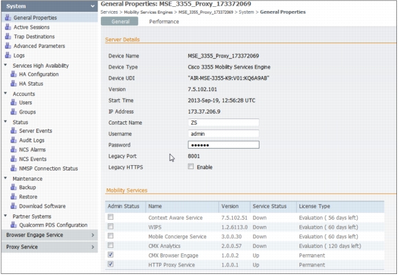
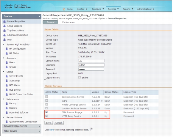
Step 1. To enable CMX Browser Engage and HTTP Proxy Services in Cisco MSE using Cisco Prime Infrastructure 1.4, choose Services >Mobility Services Engines>MSE_3355_Proxy_173372069> System >General Properties.
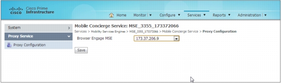
Step 2. Select Proxy Service and provide the CMX Browser Engage MSE IP address.
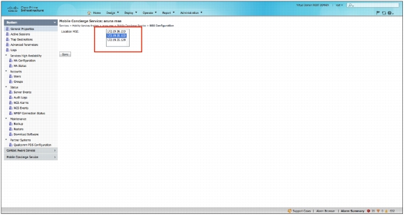
Step 3. Provide Cisco MSE Location Analytics Service information to the CMX Browser Engage server. Then click Save. After you click Save on this page, all the campus, building, and floor information managed by the selected Cisco Prime Infrastructure and Cisco MSE Location Analytics Service is sent to the CMX Browser Engage server along with the floor images and dimensions.
Configuring CMX Browser Engage
This section discusses the CMX Browser Engage dashboard and how to use it to create a campaign.
Creating a Campaign with CMX Browser Engage
The following are the main steps for creating a campaign with CMX Browser Engage:
1. The super administratorcreates a store or account.
2. The super administrator adds a store to the floor navigation with keywords to search the store (for example, coffee, café, etc. for a store like Starbucks).
3. The administrator for the store or account logs in and creates the banners required for the campaign and makes them active.
4. The administrator for the store or account creates a campaign and uses the banners at specific points of insertion(POIs).
5. The administrator for the store or account makes the campaign active.
6. The administrator for the store or account uses the Appearance tab to verify the look and feel of the campaign.
7. The administrator uses the Appearance tab to customize the way that the campaign appears in various clients.
Note: For a proof-of-concept (POC) or quick setup, the super administrator account can be used to configure the campaign.
CMX Browser Engage Dashboard
To access the CMX Browser Engage service GUI, use the URL http://<MSE_IP_address>:8081/Mario.
The default username is admin, and the default password is admin.
Note: You can create additional accounts from the Accounts tab on the Cisco CMX Dashboard.
Note: All CMX Browser Engage service accounts are both read and write enabled.
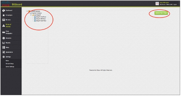
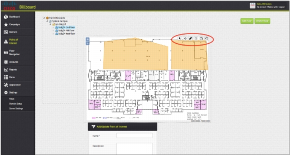
Points of Interest Tab
The Points of Interest tab shows all the campus, building, floor, and zone (POI) information pulled from the Cisco MSE Location Analytics Service. If any changes in the floor dimensions or map image are made in Cisco Prime Infrastructure, the administrator needs to manually update that information using the Update Floor Maps button.
Note: The Update Floor Maps button does not look like a typical expansion button, but it is.
The user can draw any additional POIs on the floors using the tools available on the floor map.
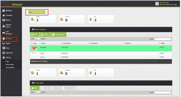
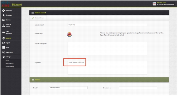
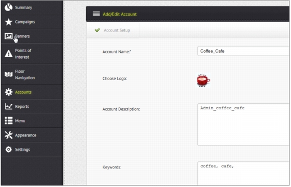
Accounts Tab
The Accounts tab lets you define different sets of accounts and users for each account and store. For example, for a shopping mall, the administrator can define separate accounts for each store: Macys, Starbucks, MacDonald's, etc. Keywords associated with each account help locate the stores when the end user searches on them. The account information is used in plotting the store in the floor navigation.
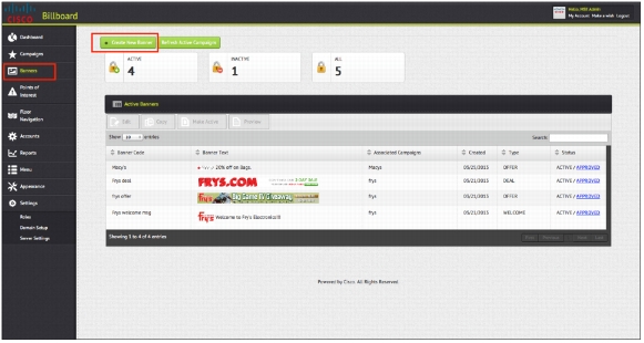
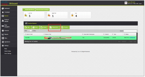
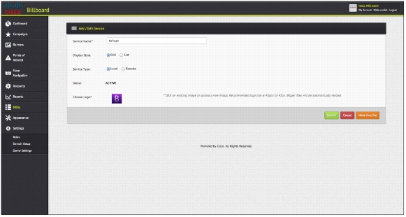
Banners Tab
To create a campaign, you need to create some banners. Banners are simply messages that float in the CMX Browser Engage toolbar.
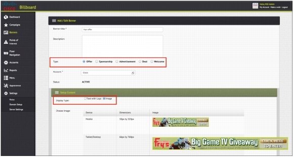
When creating banner, the administrator needs to choose the type of banner. Five types of banners are available:
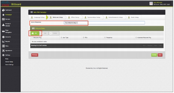
• Welcome message
• Offer
• Deal
• Sponsorship
• Advertisement
Each type has different rules and displays that the administrator can define. For example, a welcome message is displayed in the toolbar, and the administrator can choose whether the message is displayed every time the user clicks the CMX Browser Engage icon or only the first time that the user is detected. Offers and deals are displayed above the CMX Browser Engage toolbar, and the administrator can choose to provide the offer based on loyalty: for example, only after the user has remained at a specific POI for a specified amount of time.
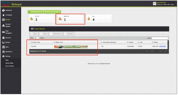
By default, all banners that are newly created are inactive. If the administrator is assigned a role that allows approval of banners, the administrator can click the Make Active button to activate a banner.
Note: Inactive banners are not displayed.
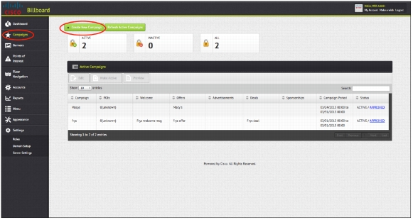
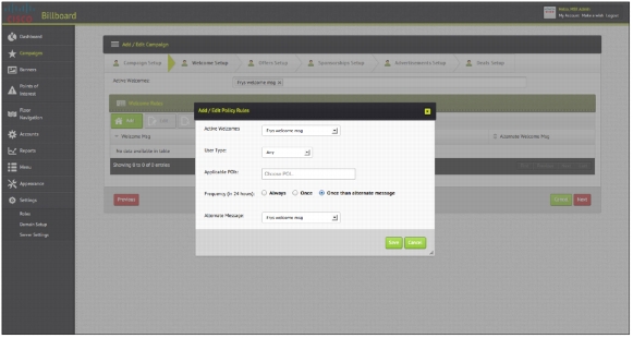
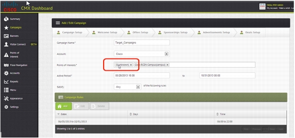
Campaigns Tab
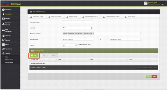
On the Campaigns tab, you create a campaign using the banners that you created and adding some rules that define when and where those banners are displayed.
In addition to the overall time period that is defined here, you can define rules that specify that the campaign is applicable only on specific days of the week and in a certain time period.
A campaign creation wizard allows you to choose the banners that are available and associate rules with each banner type.
Note: Make sure to create your banners first.
Like banners, by default newly created campaigns are inactive. If the administrator is allowed to approve campaigns, the administrator can select a campaign in the Inactive campaigns list and click Make Active to move the campaign to the Active campaigns list.
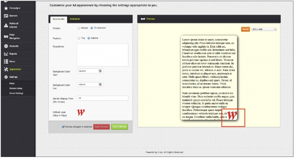
Appearance Tab
You can see how the banners appear on an end device on the Appearance tab. Here you can define the way that you want to display the toolbar and the CMX Browser Engage icon. You can also define the default icon that appears on the end device.
Some of the elements that are important on this tab are:
• Display:Defines whether the CMX Browser Engage toolbar is always expanded or is expanded only when the user clicks the icon
• Position:Defines whether the icon and toolbar should be displayed at the top or bottom of the screen
• Exceptions: Displays the icon and toolbar at the top or bottom of the screen as defined in the Position field, except for the URLs defined here
• Banner Display Time: Specifies how often each banner is refreshed
• Default Logo: Defines the default logo or icon that is displayed on the end device
• Animation tab: Specifies how the logo is displayed on the end device
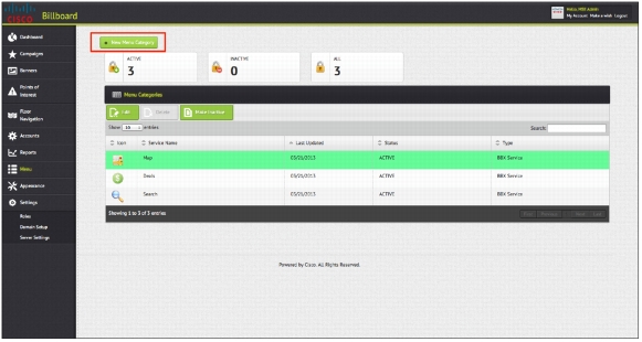
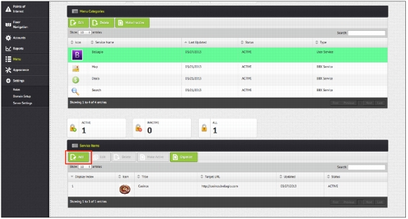
Menu Tab
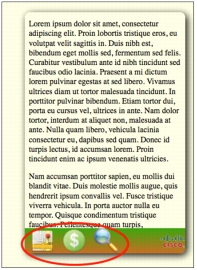
By default, three services are available on the CMX Browser Engage toolbar:
• Map
• Deals
• Search
You can define custom menu items and define service items for each custom menu item.
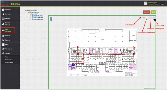
Floor Navigation Tab
When the end user clicks the Map icon in the CMX Browser Engage toolbar, the floor map is displayed along with a blue dot showing the user's current location. The user can then search for a specific item - for example, food - using a keyword entered for the account, and all the stores will be searched and locations with food will be marked on the map. Then the user can click a specific store and get directions.
Here is the process for setting up floor navigation:
Step 1. The super administrator plots all possible paths on the floor map using tools provided on the Floor Navigation tab.
Step 2. The super administrator places a store at the appropriate location on the map using the Floor Navigation tools.
Step 3. On the Accounts tab, specify all keywords for the account or store that can be used to locate the store or type of service.
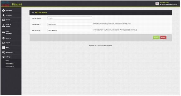
Settings Tab
On the Settings tab, the administrator can use the Domain Setup feature to define the URLs that are of interest to the venue owner. When the end user browses any of these URLs and searches for a specific keyword that matches any of the banner keywords, the CMX Browser Engage toolbar immediately expands, and a search is triggered in the CMX Browser Engage toolbar to display the banners that match those keywords. To provide this function, the administrator needs to define the URLs and the key handler that is used to search in that website. This task can be accomplished by searching on that website and viewing the URL for the search handler.
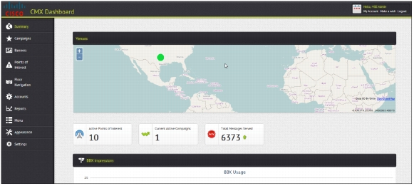
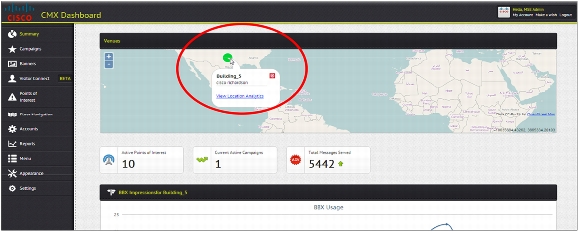
The Dashboard and Reports tabs provide data for some useful metrics.
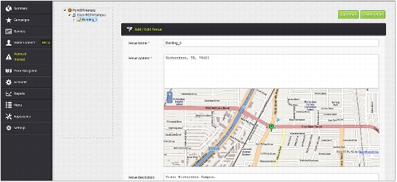
The administrator can define a civic address for a venue (building) on the Edit Venue page on the Points of Interest tab.
Note: The civic address is helpful in displaying the correct splash page, so be sure to enter it correctly for your venue.
In the dashboard, all the venues that have civic addresses defined will be displayed on the map with a green dot. When the administrator clicks the green dot, some high-level statistics appear in a pop-up window along with a link to the Location Analytics Service page. Clicking the venue also filters all the metrics shown below the map filtered by that specific venue.
Configuring the Redirection Router
This section describes the redirection methods and presents a sample configuration for each method.
Note: Regardless of which redirection method you use (PBR or Layer 4 Redirect), no particular configuration is required for Cisco MSE. By default, Cisco MSE listens to both TCP port 9090, and TCP port 80 (to accommodate PBR redirection). When outbound HTTP traffic arrives atport 80, Cisco MSE uses its internal translation table to direct the traffic from port 80 to 9090. Hence, if the redirection router in a deployment supports Layer 4 Redirect, you should configure the redirection to port 9090 at the router to free more resources on Cisco MSE.
Policy-Based Routing
PBR is available on most routers, and most network administrators are familiar with its use. Configuration is by means of a simple routemap matching HTTP traffic and then altering the MAC address of the destination to the MAC address of the IP next hop (set ip next-hop x.x.x.x). A critical point in this model is that Cisco MSE must reside in the same Layer 2 network as the PBR router.
Sample PBR Router Configuration
!
hostname PBR-Router
!
interface GigabitEthernet0/0
description<Interface towards the Clients>
ip address 192.168.1.10 255.255.255.0
ip policy route-map pbr
!
interface GigabitEthernet0/1
description<Interface to the MSE>
ip address 192.168.2.10 255.255.255.0
!
interface GigabitEthernet0/2
description<Interface towards the INTERNET>
ip address 192.168.3.10 255.255.255.0
!
!# default route towards the Internet
ip route 0.0.0.0 0.0.0.0 192.168.3.254
!
!# the access list matches traffic from the client subnet to TCP port 80
access-list 2000 permit tcp 192.168.1.0 0.0.0.255 any eq www
!
route-map pbr permit 10
matchip address 2000
setip next-hop 192.168.2.15
!# the "set" command syntax should not be confused to be altering the "IP" address of next hop. What really happens here is that the router applies ARP to the defined IP address, and changes the destination "MAC" address only of the traffic matching the ACL to the MAC address of the Cisco MSE NIC with the defined IP address (here,192.168.2.15).
!
!
end
Layer 4 Redirect
Layer 4 Redirect is available on high-end routers providing subscriber services (usually found in hospitality and service provider deployments). Configuration may appear more complicated, but in essence the feature matches the HTTP traffic from the enduser and redirects it. Layer 4 Redirect allows alteration of both the Layer 3 and Layer 4 destination information (destination IP address and destination port): hence, the name Layer 4 Redirect.
With Layer 4 Redirect, Cisco MSE can be located anywhere inthe network as long as it can be reached using IP. In addition, typical load-balancing techniques can be used to scale the capacity of the proxy solution.
Note: One of the primary reasons to use Layer 4 Redirect is that it allows Cisco MSE to be located anywhere.
Routers capable of Layer 4 Redirect usually also support failover mechanisms using a combination of IP service-level agreements (SLAs)and event management applets (see the sample configuration in the "References" section at the end of this document).
Sample Layer 4 Redirect Configuration
!
hostname ASR1K
!
aaa new-model
!
aaa authorization subscriber-service default local
!
subscriber authorization enable
!
!# the following command define the MSE proxy IP(s) and the respective Port(s) they are listening to
redirect server-group CMX BROWSER ENGAGE_PROXY
serverip 192.168.2.15 port 9090
!
!# the following configuration define the Control Policy that activates L4-Redirect service when a subscriber session is first detected, and the traffic match the condition set by the ACL (to http)
class-map type traffic match-any CMX BROWSER ENGAGE_L4
match access-group input name L4_ACL
!
policy-map type service CMX BROWSER ENGAGE_L4_Policy
10 class type traffic CMX BROWSER ENGAGE_L4
redirect to group CMX BROWSER ENGAGE_PROXY
!
!
policy-map type control CMX BROWSER ENGAGE_L4_REDIRECT
class type control always event session-start
10 service-policy type service name CMX BROWSER ENGAGE_L4_Policy
!
interface TenGigabitEthernet0/0/0.91
description<Interface towards L4RDCT Clients>
encapsulation dot1Q 91
ip address 192.168.11.10 255.255.255.0
service-policy type control CMX BROWSER ENGAGE_L4_REDIRECT
ip subscriber l2-connected
initiator unclassified mac-address
!
interface TenGigabitEthernet0/0/0.92
description<Interface to the MSE>
encapsulation dot1Q 92
ip address 192.168.2.10 255.255.255.0
!
interface TenGigabitEthernet0/0/0.93
description<Interface towards the INTERNET>
encapsulation dot1Q 93
ip address 192.168.3.10 255.255.255.0
!
ip route 0.0.0.0 0.0.0.0 192.168.3.254
!
!# a numbered ACL - like the one in the PBR example- would have served the same purpose
ip access-list extended L4_ACL
permittcp 192.168.11.0 0.0.0.255 any eq www
!
!
!# adding the following aliases obviously are not mandatory, but can be handy for troubleshooting
alias exec sss show subscriber session
alias exec css clear subscriber session
alias exec srt show redirect translation
!
end
Troubleshooting
This section provides some techniques to help troubleshoot CMX Browser Engage deployments.
No Internet Pages Loading on the Client
If Internet pages do not load on the client, check whether other Internet traffic (other than traffic on TCP port 80) is passing through (for example, non-HTTP email, HTTPS, and application traffic).
If the problem occurs with all Internet traffic, then check the routing, and possibly temporarily remove PBR or Layer 4 Redirect to simplify troubleshooting.
If the problem is specific to HTTP traffic (port 80) and other Internet applications are functional, troubleshoot according to the problem with the requested HTTPpage.
• If the requested page is timing out: Verify that PBR or Layer 4 Redirect is indeed intercepting the traffic and directing it to Cisco MSE (see the show route-map counter example in the following section called " The Page Is Loading, but the Banner Does Not Appear"
• You may have an incorrect Cisco MSE IP address or redirection port configured in the redirection rule for the router.However, if you find that the traffic is indeed reaching Cisco MSE, check the following:
– Confirm that the HTTP Proxy Service is running by entering get server info from the Cisco MSE CLI or from the Cisco Prime Infrastructure GUI.
– If HTTP Proxy Serviceis already enabled, check that Cisco MSE can reach the client subnet, and that it has Internet connectivity (for example, from the CLI ping an active client IP address and http://www.ask.com).
– If the client and Internet are reachable but the problem persists, try restarting HTTP Proxy Service. From Cisco Prime Infrastructure, uncheck the box next to HTTP Proxy Service and click Save. After the screen refreshes and the service is shown as Down, recheck the box and click Save again and confirm that the service is now listed as Up.
• If you receive the "HTTP Error: 502 Bad gateway" message: This message means that your redirection configuration on the router is successfully sending the traffic to a Cisco MSEproxy. In this case, the problem is probably related to your Cisco MSE proxy settings (confirm that you can reach DNS from Cisco MSE; you may have configured a bad DNS IP address).
Note: CMX Browser Engage redirects only HTTP traffic; however, about 5 percent of the sites on the Internet and 100 percent of the sites that permit financial services transactions use HTTPS. When a website uses an HTTPS connection between the client and the server, a proxy cannot inject traffic. About 90 percent of all websites use HTTP because it is easier and cheaper to deploy than HTTPS, but 10 percent of all websites, including several large sites such as Facebook.com and Google.com, default to an HTTPS connection.
The Page Is Loading, but the Banner Does Not Appear
If the page loads, but the banner does not appear, do the following:
1. From the client's browser, view the loaded HTTP webpage source (for example, in Google Chrome, right-click the page and choose View Page Source).
2. Search for the string CMX Browser Engage.
3. If the string CMX Browser Engage is found in the page source code, but the banner is still not loading, look for this statement:
The value <CMX Browser Engage-server> is the variable you configured earlier in Cisco Prime Infrastructure (see the section "Provide CMX Browser Engage Server Information to Proxy Service"). If the variable is configured correctly, it should display the CMX Browser Engage service IP address or a valid resolvable hostname pointing to it. If instead you see the exact string CMX Browser Engage-server displayed instead of the proper IP address, confirm that the configuration is correct using the Cisco Prime Infrastructure interface (see "Provide CMX Browser EngageServer Information to Proxy Service").
4. If,after viewing the webpage source code, you find that the CMX Browser Engage script was not inserted:
a. Check that the router is indeed intercepting the HTTP traffic: for PBR, watch the counters on the PBR route map (they should increase), and for Layer 4 Redirect, view the subscriber redirect translation. A PBR example is shown here:
PBR-Router#sh route-map
route-map pbr, permit, sequence 10
Match clauses:
ip address (access-lists): 2000
Set clauses:
ip next-hop 192.168.2.15
Policy routing matches: 369 packets, 24930 bytes
b. Check that the proxy Cisco MSE interface is receiving the intercepted traffic:
/opt/mse/proxy/bin/exec_show_stat_proxy.sh
From the output of the this command, verify the following:
• The IP table rule is inserted.
• IP forwarding is enabled.
c. For more details, collect trace information using tcpdump (tcpdump.rpm is included in /opt/mse/proxy/bin). To install tcpdump, enter the command rpm -ivh<tcpdumpx.x.rpm> as shown in this example: (Note the x.x.rpm refers to version numbers and platforms, Use the example below for version number 3.4a5-3 on the i386 platform (ie Intel).
rpm -ivhtcpdump-3.4a5-3.i386.rpm
Atcpdump trace on the Cisco MSE, client, or HTTP server device is often a very useful troubleshooting tool. The following code provides sample syntax:
d. You can also check the proxy error logs, located at /opt/mse/proxy/nginx/logs/error.log using grep to filter the output to see only the client IP being debugged.
Note: In the case of PBR, if Cisco MSE is running, and the proxy service is not enabled, Cisco MSE will still allow Internet traffic to pass through (this is not the case with Layer 4 Redirect). Always make sure that the required services are indeed running (for more information, see the section "Enabling CMX Browser Engage from Cisco Prime Infrastructure".
References
Proxy Error and Access Logs
Proxy-related logs are located in:
/opt/mse/logs/proxy/
/opt/mse/logs/proxy/proxy-hmon.out(Proxy Health Monitor logs)
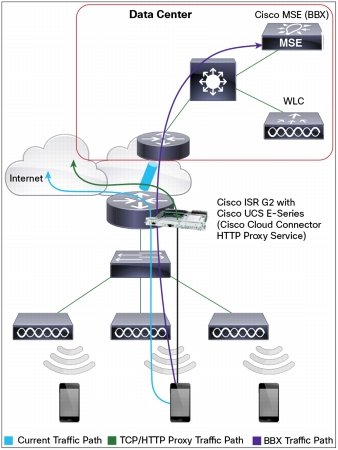
Running CMX Browser Engage in Cisco Flex Local Mode
For Cisco Flex local deployments, the HTTP Proxy Service feature needs to be enabled locally at the remote site, where client traffic is being switched. For this type of deployment,you can use Cisco ISR G2 with a Cisco UCS E-Series Server, which will run the Cisco Cloud Connector (sometimes referred to as C3) proxy feature (Figures 6 and 7).
The Cisco Cloud Connector proxy feature uses the Cisco Open Network Environment (ONE) Platform Kit (Cisco onePK)service set to intercept local traffic and insert the scripts needed for CMX Browser Engage.
The following process occurs at the local router:
1. The router interface is configured to intercept packets and to redirect all client traffic to the Cisco UCS E-Series Server.
2. Cisco Cloud Connector HTTP Proxy Service terminates the client TCP connection and binds to port 80 to receive all HTTP traffic.
3. HTTP Proxy Service binds to the client's IP address and port number and opens a new TCP connection to the destination web server (acts as an endpoint).
4. HTTP Proxy Service intercepts server responses, inserts billboard (BBX) ad script in the HTTP message, and forwards the response to the client.
5. The client browser runs the inserted ad script to fetch the ad from the BBX ad server.
Figure 6. Cisco Flex Deployment with Enterprise Cisco ISR
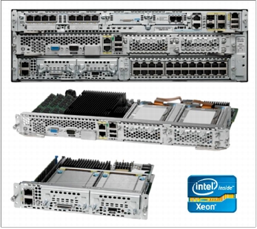
Figure 7. Cisco UCS E-Series Servers with Cisco 3945 ISR
Following are the prerequisites for using the Cisco CMX dashboard connector:
• You must have a Cisco ISR G2 with Cisco IOS® Software Release 15.3-M0.2 or higher (a Cisco IOS Software release with Cisco onePK support is needed).
• You must have a Cisco UCSE-Series Server with VMware ESXi 5.1 preinstalled.
• The Cisco UCSE-Series server needs 4GB of memory, four virtual CPUs (vCPU), and a 250GB hard drive.
• The Cisco UCSE-Series Server module must be installed in the Cisco ISR.
• You must have configured the Cisco UCSE-Series parameters such as the IP address and networking through the Cisco Integrated Management Controller (IMC) GUI.
• You must be able to access VMware ESXi on the Cisco UCSE-Series module through the VMware vSphere client.
• You must have the Cisco Cloud Connector proxy Open Virtualization Format (OVA) file C3-CMX-1.0.0.ova.
Note: Cisco ISR G2 routers that support the Cisco CMX dashboard are Cisco 2911, 2921, 2951, 3925, and 3945 ISRs ("E" versions of the Cisco ISR G2 routers are not supported).
Follow the steps presented here to configure Cisco Cloud Connector Proxy.
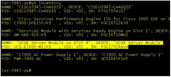
These steps assume that the Cisco UCSE-Server blade is installed in slot 4 of the Cisco 3945 ISR G2. To check, use the show inventory command:
Step 1. Configure the router as follows:
• Use Cisco IOS Software Release 15.3(3)M with Cisco onePK installed.
• Configure the interface for the wireless client traffic (the gateway for wireless clients).
• Configure the Cisco UCSE-Series slot with the Cisco IMC IP address.
• Set a maximum transmission unit (MTU) of 1700 on the Cisco UCSE-Series interface.
• Configure the interface for a generic route encapsulation (GRE) tunnel between the router and the Cisco Cloud Connector proxy.
• Configure the Cisco onePK settings.
• Configure the username and password with privilege 15 to be used in the Cisco Cloud Connector HTTP Proxy Service configuration (to be used in the Cisco Cloud Connector web management user interface).
• Set the routes from the router to access the Cisco UCSE-Series module for the VMware ESXi server and Cisco Cloud Connector proxy.
Note: When using this type of deployment, you are using Cisco onePK and not PBR to move the packets from the router to the Cisco MSE proxy, but the router is still essentially performing the same function; it is just using a different method.
The configuration shown here uses a dedicated port (an Ethernet cable is plugged into the Cisco UCSE-Series Server IMC port). You can configure access to the Cisco MIC port through the router (no Ethernet cable plugged into the Cisco UCSE-Series Server) using the command imc access-port shared-lom. Be sure to include the route to the Cisco IMC port through the router if you use shared-lom.
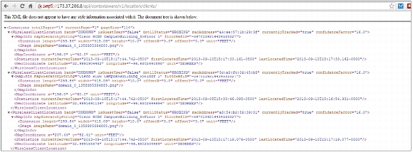
Be sure that appropriate routes have been setup on the Cisco ISR to access the VMware ESXi server through the Cisco UCSE-Series slot. The following example shows a route to the VMware ESXi host and Cisco Cloud connector that will be deployed in the next step:
ip route 173.37.206.12 255.255.255.255 ucse4/0 (route to ESXi host)
ip route 173.37.206.13 255.255.255.255 ucse4/0 (route to C3 connector running on ESXi host)
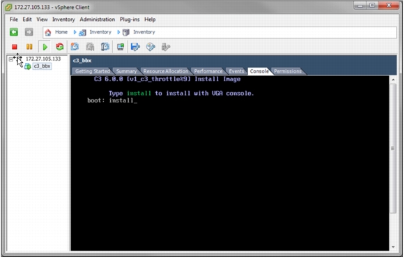
Step 3. After VMware ESXi has been loaded onto the Cisco UCS E-Series Server, deploy the Cisco Cloud Connector OVA file on the VMware ESXi server using the VMware vSphere client.
Step 4. After the Cisco Cloud Connector OVA file has been deployed, the Cisco Cloud Connector installation process can begin. You get access to the VGA console of the virtual machine. Enter install to install the Linux-based Cisco Cloud Connector hosting environment.
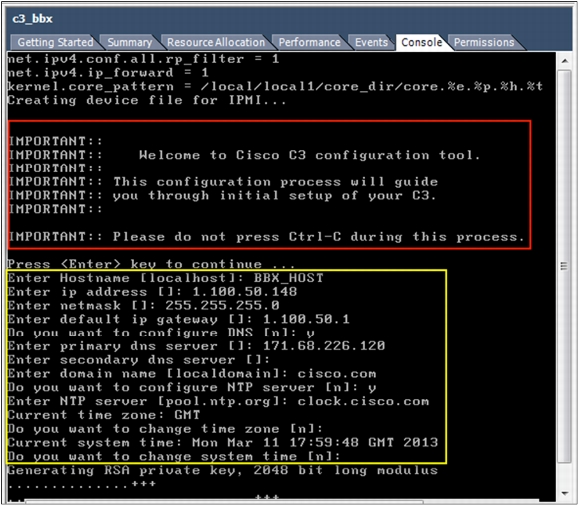
At the first installation of the OVA file, you will be prompted for the initial setup of the system, needed for setting the Admin users, networking, time zones, etc.
The setup utility sets up two system users:
root and Admin.
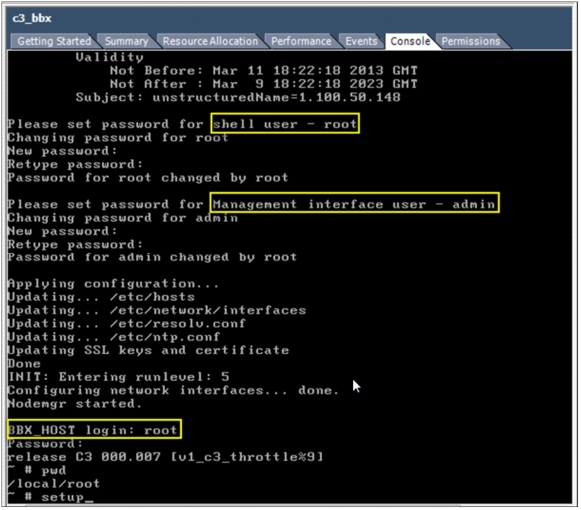
The VGA console transitions to the login prompt for the interactive Linux shell. Only the root user can log into the Linux shell. The Admin user administers the web user interface.
You can rerun the setup utility to change the configured parameters by entering the "setup" command at the shell.
After the initial networking setup is complete, the Linux shell can also be accessed using an SSH client. The interactive Linux shell is used mainly fordebugging and troubleshooting. Most other management and configuration tasks are performed using the web user interface.
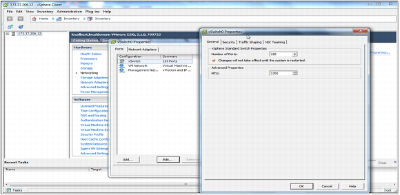
Step 5. After the Cisco Cloud Connector proxy has been installed and configured, set the MTU size to 1700 so that the Cisco Cloud Connector proxy processes packets accurately.
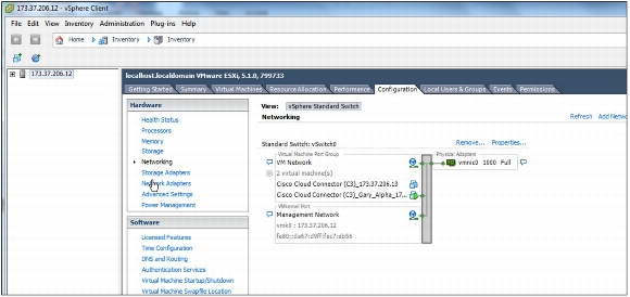
a. Select the host machine and open the Configuration tab and select Networking.
b. Under Standard Switch: vSwitch0, select the propertiesyou want to set and click Edit. Click OK to apply the settings.
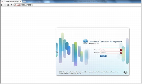
Step 6. Access Cisco Cloud Connector. When the setup utility is complete, the Cisco Cloud Connector Connector management web user interface is accessible from a browser. The username is admin and the password is the one you specified during Cisco Cloud Connector setup.
Step 7. ConfigureCisco Cloud Connector.
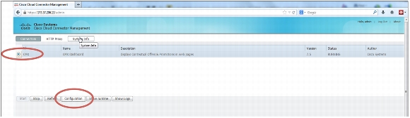
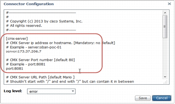
a. After you are logged into the web management user interface of Cisco Cloud Connector, select the Connectors tab and click the CMX button. Then select the Configuration tab at the bottom of the screen.
b. In the configuration file that opens, enter the Cisco MSE (portal) IP address and port number to access the Cisco CMX Dashboard portal. The example shown here uses IP address 173.37.206.7 and port 8081.
c. When the configuration is complete, click Save.
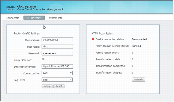
Step 8. Configure the HTTP Proxy Service on Cisco Cloud Connector.
a. Select the Http Proxy tab from with the management user interface.
b. Under Router OnePK Settings, enter the interface IP address for the router interface that will be sending traffic to the Cisco Cloud Connector application. This example uses the VLAN1 interface with an IP address of 10.100.100.1. Also enter the username and password that you created on the router (with Privilege 15 access).
c. Enterthe interface on which the interception of traffic will occur. The example here uses the wireless client subnet interface GigabitEthernet0/2.245 on the LAN side.
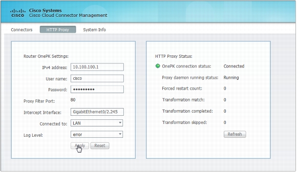
d. After the appropriate information has been entered, click Apply. The HTTP Proxy Service status should change from "OnePK connection status: Disconnected" to "OnePK connection status: Running."
Note: The Cisco Cloud Connector management GUI looks like the Cisco Prime Infrastructure GUI, but it is not connected to Cisco Prime Intrastucture.
e. To verify connectivity from the router side, enter the command Show onep datapath. The GRE status should be up, and both the local and remote addresses should be shown.
Your CMX Browser Engage service should now be ready for use (assuming that you have your campaigns setup in the Cisco CMX dashboard on Cisco MSE; if you do not, see the "CMX Browser Engage Service Configuration" section of this document for configuration details).
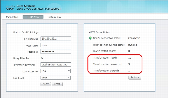
Step 9. Verify that the Cisco Cloud Connector proxy is processing client traffic by selecting the HTTP Proxy tab. Look at the "Transformation match" and "Transformation completed" counters.If they are incrementing, then the Cisco Cloud Connector proxy is receiving intercepted traffic bound for port 80.
Tips
You can change the location of the green dot on the CMX Browser Engage start page.
On the Point of Interest tab, edit the address of the venue. The address is based on its OpenStreetMap location (openstreetmap.org).
If banners do not appear in the client, but the show route-map debug command on the router shows matching packets and no 502 errors in the browser, check whether client appears in the location or zone in the Cisco MSE running location services (CAS). Search for the MAC address of your client.
If the client MAC address is not found, then the client is not seen by the Cisco MSE location service. Verify that the access point to which you are connected is within a zone on the mapin Cisco Prime Infrastructure. In the Points of Interests field for the campaign, choose the 0(unknown) location. Now the banner will be shown no matter what zone the client is in.
CMX Browser Engage Service Specifications and Considerations
Keep these points in mind when using the CMX Browser Engage service:
• HTTP Proxy Service can run on a Cisco 3355 MSE (for central switched environments) or a Cisco ISR running a Cisco UCS E-Series module (for Cisco Flex deployments).
• The Cisco CMX dashboard and HTTP Proxy Servicecan run together if deployed on a Cisco 3355 MSE or standard Cisco VMSE (no additional services should be deployed on this Cisco MSE).
• HTTP Proxy Service is supported on all Cisco MSE platforms except the high-end Cisco MSEvirtual machine.
• The maximum supported throughput for HTTP Proxy Service running on the Cisco 3355 MSE and standard Cisco VMSE is approximately 660 Mbps with 2000 connections per second (cps).
• The maximum supported throughput for HTTP Proxy Service running on the Cisco ISR and Cisco UCS E-SeriesServer with Cisco Cloud Connector is approximately 60 Mbps.
• The Microsoft Internet Explorer (IE) browser is not supported for CMX Browser Engage service in Cisco MSE Release 7.5.
• Certain pages on certain devices may not be rendered as expected, especially if a site is redirected to a mobile version of a page at m.sitename.com. The results can be unexpected.