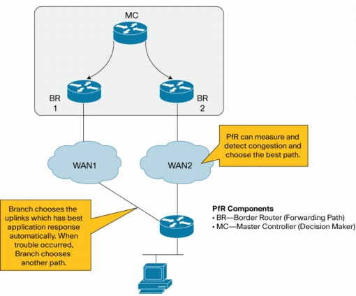
Benefits of using Performance Routing (PfR): PfR enables intelligent traffic management that can dynamically route around soft errors in the Enterprise WAN or Internet. PfR also enhances routing to select the best path based on user defined policy. PfR policy can be used to minimize cost, efficiently distribute traffic load, and select the optimum performing path for applications. PfR makes adaptive routing adjustments based on following advanced criteria: Response time, packet loss, jitter, mean opinion score (MOS), availability, traffic load, and cost ($) policies. In summary, PfR makes Redundant VPN networks in Enterprise highly available by detection of problems in the network, faster router convergence, and of effective usage of redundant paths by using policy based routing.
Figure 1. Performance Routing (PfR)
Objective: This document is solution deployment guide for the High Available Redundant VPN networks using the PfR technology.
Following three common solution test cases are covered in this document:
Most of the traffic is routed via MPLS private WAN path. When there is an overflow or error condition in the MPLS path, traffic will be routed to the Public WAN path. Also traffic will be routed based on PfR Traffic class.
Route traffic during Blackout and Brownout conditions in the MPLS network:
Failover from MPLS VPN network path to public L3 VPN network path using PFR to address the blackout and brownout conditions in the MPLS network. PfR should pass traffic through Public WAN when high level traffic loss (>= 20%) is detected in private WAN. When loss is recovered in the MPLS path, traffic should be re-routed through MPLS path
– When there is brownout (high loss and/or extreme delays) or blackout (total loss of data packets) in the MPLS network path, move all traffic to the public WAN
– Use PfR based on network prefix without using the traffic class
– If utilization in MPLS link reaches 80%, route the excess traffic via Public WAN
– Utilization and errors recover in MPLS path, all traffic switches back to the MPLS path
Route traffic based on traffic load, response time, and jitter:
Use performance policy for critical applications including voice and use load policy for data distribution using PfR to fully utilize over used and under used links.
– If Utilization in MPLS link reaches 80 %, route excess data traffic via Public WAN.
– Route voice traffic to the Public WAN instead of using the MPLS network, if there is increase in delay or latency or jitter of data packets in the MPLS path.
– Route all traffic back to MPLS path when utilization and errors recover in the MPLS path.
Select optimum performing path for applications:
Use PfR traffic class based routing
– Use PfR traffic class based routing to route voice and video traffic over MPLS and route data traffic over the public WAN
– If moderate level traffic loss is noticed in MPLS path (>=5%), all traffic is routed to the Public WAN
– When traffic loss error is recovered in the MPLS path, traffic flows according to the PfR traffic class configuration.
Table of Contents
1 Network topology
Following outlines the solution test setup topology used for testing PfR in redundant VPN networks:
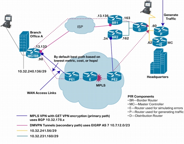
• Routing protocols used: Redundant VPN networks between Branch A and Headquarters contain MPLS private network as the primary routing path and ISP network with DMVPN encryption as the secondary routing path. PfR does not have any dependency on encryption method used. GET VPN encryption is used on the MPLS network path in the solution test setup. But solution also works if GET VPN encryption is not used on the primary VPN. Customer and service provider equipments connected to the MPLS private network use BGP routing protocol. Customer and service provider equipments connected to ISP network use EIGRP routing protocol.
• VPN network details: Following lists the details of the redundant VPN networks:
1. GETVPN encryption/decryption is done at edge router CE devices in the MPLS network. PfR MC/BR router in Branch Office A and BR2 router in the Headquarters will do the GET VPN encryption and decryption.
2. DMVPN encryption/decryption is done at the MC/BR router in Branch Office A and BR1 router in Headquarters.
Figure 2. Solution test setup topology used for testing PfR
Equipments list: Following lists equipments used in testing:
• MC and BR PfR functions are co-located in the CE router located in the Branch A. Video phone and laptop are connected to a VLAN in that branch router. This branch router is connected to the MPLS network via PE1 Service Provider router and also it is connected to ISP network.
• MC and BR PFR functions are separated in the headquarters due to the performance reasons. Performance of BR router forwarding aggregate traffic is high. Hence the MC function is done on a separate router in the headquarters.
• BR2 Border router is located in the headquarters. Border router BR2 is connected to the MPLS network via PE2 Service Provider router.
• BR1 Border router is located in the headquarters. Border router BR1 is connected to the ISP network.
• BR1 and BR2 are connected to the same Vlan in a router, and BR2 is one IP hop away from BR1 to enable the Policy Based routing required for the PfR.
• PfR MC router is located in the headquarters. It is connected to the same vlan as Pagent router P, Video phone and a laptop.
• Traffic Generator P is used for generating traffic
• Router D is a distribution router connected to both BRs in the headquarters and headquarters VLAN represented in orange color in the above diagram
• Router E is setup in the MPLS network is used for simulating errors including jitter, packet loss and delay.
2 Configuration
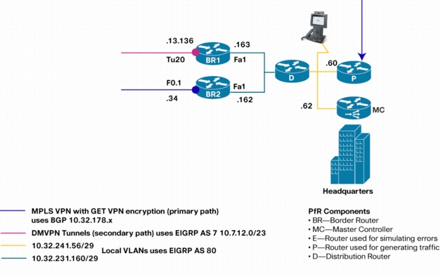
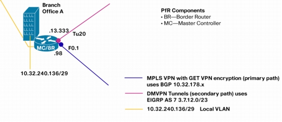
Following figures show the topology of PfR components in Headquarters and Branch Office A
Figure 3. Solution test setup topology used in Headquarters
Figure 4. Solution test setup topology used in Branch Office A
Following sections provide configuration commands needed for provisioning PfR. Following are common PfR configuration commands in the Master Controller router MC in the headquarters.
! This is the basic configuration required to establish session
! between MC and BR. It includes
! - Key-chain configuration for authentication.
! - Specification of BR's IP Address and internal/external interface
! on the BR.
! - Specification of link-group for each external interface. In this
! case it is MPLS and DMVPN.
! - Specification of Maximum transmit utilization of 80% on MPLS
Following are common PfR configuration commands in the Border Router BR1 and BR2 in the headquarters.
! This is the minimum configuration required to BR. It includes
! - Key-chain configuration for authentication.
! - Specification of MC's IP Address and Local interface. The IP address
! of the local interface will be used as source IP address in communicating
! with MC.
key chain PFR-SOL-TEST
key 1
key-string 7 *perfrtg
!
oer border
logging
local FastEthernet1
master 10.32.241.62 key-chain PFR-SOL-TEST
!
2.1 PfR test case for MPLS network blackout and brownout
Summary
Failover from MPLS VPN network path to public L3 VPN network path using PFR to address the blackout and brownout conditions in the MPLS network. PfR should pass traffic through Public WAN when moderate level traffic loss ( >= 20%) is detected in private WAN. When loss is recovered in the MPLS path, traffic should be re-routed through MPLS path. In order to achieve this there are three tasks.
1. Identify traffic
The policy is applied to all traffic destined to a specific branch. In other words there are no separate policies for different applications (as there are in next test case). So a single learn list per branch is used to learn branch specific prefixes.
2. Determine policy parameters
• Unreachable threshold is configured to detect the blackout and brownout condition. For example out of 10 probe packets, if 5 proe packets are not reachable, then Unreachable measurement is 50% (500,000 flows per million)
• PfR makes the decision in the order of priority. Unreachable is the first priority and cannot be overridden. So there is no need to set unreachable priority. However, there are some default priorities for delay and utilization that should be disabled.
• Active probes are configured to measure the reachability. More than one probe is configured to improve the measurement.
• Fast mode and lower probe frequency are configured to reduce the reaction time. Reaction time is the time it takes to mitigate the error condition (here blackout and brownout) since it is detected.
• Periodic timer is configured to enable switching traffic back to MPLS when it is back to Normal conditions (no blackout or no brownout).
• Specify the primary link group (here MPLS) and the fallback link-group (here DMVPN)
Configuration
Following lists PfR configuration in the MC router in the Headquarters:
! Following is a learn list configuration specific to one branch.
! This should be repeated for each branch. It includes
! - Learning destination-only traffic-class that matches prefixes specified in the
! prefix-list BRANCH1_PREFIX.
! - `aggregation prefix-length 32' is configured to monitor and control
! traffic-class at granularity of /32 (eg 10.1.1.1/32)
! - throughput command is to sort the traffic-class based on throughput at the end
! of learn cycle.
oer master
learn
list seq 20 refname LEARN_LIST_BRANCH1_PREFIX
traffic-class prefix-list BRANCH1_PREFIX
aggregation-type prefix-length 32
throughput
!
ip prefix-list BRANCH1_PREFIX seq 5 permit 10.32.240.136/29
! Following is a policy configuration specific to one branch.
! This should be repeated for each branch. It includes
! - match command is to specify that this policy should be applied
! to all the traffic-class learned under list LEARN_LIST_BRANCH1_PREFIX.
!
! - periodic: Every 90 second each traffic class is re-evaluated.
! It is required to bring the traffic-class back to primary link
! (MPLS) when the utilization drops below the limit. A Higher value
! can be used if longer time to switch back to primary link is acceptable.
!
! - Unreachable threshold is set to 200,000 (Flows-per-million) i.e 20%
! Unreachability.
!
! - monitor mode is set to fast. This means probe all external interfaces
! all the time. When Out-of-Policy condition is detected on the current exit
! results on alternate exit is available for quick decision. In other modes
! alternate exits are probed only when current link is determined to be OOP.
! The fast mode helps in switching the path quickly when the problem
! is detected.
!
! - The requirement is to only switch when the blackout/brownout (unreachable)
! occurs OR when the utilization exceeds the threshold.
! Unreachable is ON by default and cannot be disabled.
! Delay and Range is ON by default, so it is turned off.
! Utilization is set to priority 2 with variance 10. Variance 10 means that
! if the free BW on the link are within 10% of each other then they are equal.
!
! - Probe frequency is set to 4 second to detect the problem quickly. For
! critical application such as video lower probe frequency is desirable.
!
! - MPLS is set as primary link-group and DMPVN is set as fallback link-group.
!
! - UDP probe is configured because only reachability is required. Two probes are
! configured for better result. Each probe sends control packet followed by
! probe packet. `ip sla responder' should be configured on target router on the
! branch side.
oer master
policy-rules MAP-TEST1
! OER Map
oer-map MAP-TEST1 10
match oer learn list LEARN_LIST_BRANCH1_PREFIX
set periodic 90
set unreachable threshold 200000
set mode monitor fast
set resolve utilization priority 2 variance 10
no set resolve delay
no set resolve range
set probe frequency 4
set link-group MPLS fallback DMVPN
set active-probe udp-echo 10.32.240.137 target-port 3000
set active-probe udp-echo 10.32.240.137 target-port 3001
! VERY IMPORTANT CONFIG
! =====================
! Turn ON the route control and set the control protocol to `pbr'.
! By default the control mechanism is in the order, BGP, EIGRP, STATIC and PBR.
! In DMVPN (EIGRP)/ MPLS (BGP) environment route control using either BGP or EIGRP
! results into failure or ineffective control. The only option that
! works is using PBR. So it is necessary to set `router protocol pbr' to
! force PfR to use PBR as control mechanism.
Oer master
! This command is only available in version 15.0(1)M4 and later
mode route protocol pbr
mode route control
2.2 PfR performance and load policy test case
Summary
In this test the goal is to use performance policy for critical applications including voice and use load policy for data distribution using PfR to fully utilize over used and under used links.
Under normal condition all traffic should be sent over MPLS network. If there is performance issue, for example loss is > 5% then Video and Voice traffic should be switched over to public L3 VPN. If there is excess traffic i.e utilization is > 80% then non-critical traffic should be switched to public L3 VPN.
1. Identify traffic
There are two sets of traffic. One is critical application (voice and video) and the other is remaining traffic. In order to apply different policy it is necessary to configure two learn list. One identifies the application (here based on dscp af41) and the other learns the remaining traffic.
2. Determine policy parameters
• For non-critical traffic the only change is the addition of utilization priority. When the utilization on MPLS link is > 80% it is desired to move the excess non-critical traffic to DMVPN link.
• Another policy (MAP-TEST2 10) is created for critical application.
• Loss threshold is set to 50000 packets-per-million (5%). Loss larger than 5% degrades the video quality significantly. For example out of 100 probe packets closely interleaved, if 5 packets dropped, then Loss measurement is 5% (50,000 packets per million)
• Jitter larger than 30 msec also leads to poor video quality.
• Delay threshold is set to 300 msec because delay higher than that could degrade the Quality of Experience in video-conferencing.
• The order of priority is set to loss, jitter and delay based on the impact each metrics could have on video.
• The probe type is jitter because only jitter probe can measure loss/jitter/delay.
• Rest of the configuration is very similar to policy for non-critical traffic.
Following lists PfR configuration in the MC router in the Headquarters:
Configuration
! Following is a learn list configuration for video application
! specific to one branch.
! This should be repeated for each branch. It includes
! - Here Video (assuming it is marked as af41) is learned using
! access-list DSCP_VIDEO and brach specific filter BRANCH1_PREFIX.
! - Every thing else remains the same.
! This configuration will learn following traffic-class
! - monitor mode is set to `active throughput' instead of `fast'. For non-critical
! traffic it is not necessary to switchover quickly. By changing to
! `active throughput' mode probed traffic is reduced because it only probes
! current exit most of the time.
! - Probe frequence can also be changed to a higher value.
oer-map MAP-TEST2 20
match oer learn list LEARN_LIST_BRANCH1_PREFIX
set periodic 90
set unreachable threshold 200000
set mode monitor active throughput
set resolve utilization priority 2 variance 10
no set resolve delay
no set resolve range
set link-group MPLS fallback DMVPN
set probe frequency 4
set active-probe udp-echo 10.32.240.137 target-port 3000
set active-probe udp-echo 10.32.240.137 target-port 3001
2.3 PfR traffic class based routing test case
Summary
In this test the goal is to use MPLS link as primary link for critical application such as video while use DMVPN link as primary link for non-critical application. It is still desired to move critical application to DMVPN when MPLS link is not performing (loss > 5%). Similarly, if the utilization on DMVPN is > 80% then excess non-critical traffic is moved to MPLS if there is enough BW to accommodate. This configuration allows the better use of DMVPN link by distributing critical and non-critical traffic.
1. Identify traffic
This remains the same as in previous test case.
2. Determine policy parameters
• There are two changes. First change from the previous test case is that primary and fallback link for non-critical application traffic is switched. i.e DMVPN is primary and MPLS is fallback. The second change is that monitor mode active throughput is used.
• There is no change in policy for critical application.
Configuration
! Config on HQ
! 80% Threshold is set on DMVPN link.
oer master
border 10.32.231.163 key-chain PFR-SOL-TEST
interface Tunnel20 external
max-xmit-utilization percent 80
oer-map MAP-TEST3 10
match oer learn list LEARN_LIST_BRANCH1_VIDEO
set periodic 90
set delay threshold 100
set loss threshold 50000
set jitter threshold 30
set mode monitor fast
set resolve loss priority 2 variance 5
set resolve jitter priority 3 variance 5
set resolve delay priority 4 variance 5
no set resolve range
no set resolve utilization
set link-group MPLS fallback DMVPN
set probe frequency 4
set active-probe jitter 10.32.240.137 target-port 2001 codec g729a
set active-probe jitter 10.32.240.137 target-port 2002 codec g729a
set active-probe jitter 10.32.240.137 target-port 2000 codec g729a
! - monitor mode is set to `active throughput' instead of `fast'. For non-critical
! traffic it is not necessary to switchover quickly. By changing to
! `active throughput' mode probed traffic is reduced because it only probes
! current exit most of the time.
! - Probe frequence can also be changed to a higher value.
oer-map MAP-TEST3 20
match oer learn list LEARN_LIST_BRANCH1_PREFIX
set periodic 90
set unreachable threshold 200000
set mode monitor active throughput
set resolve utilization priority 2 variance 10
no set resolve delay
no set resolve range
set link-group DMVPN fallback MPLS
set probe frequency 4
set active-probe udp-echo 10.32.240.137 target-port 3001
set active-probe udp-echo 10.32.240.137 target-port 3000
3 Verification
The test is verified using two show commands.
show oer master traffic-class
This command displays the current information about all the traffic-class. It includes the state, current exit through which the traffic-class is routed, and performance metrics associated with traffic-class.
• State of the traffic-class will change to HOLDDOWN after it is moved to a different exit.
• State is set to INPOLICY if the performance of the traffic-class is within the set thresholds.
The state and the current exit fields are used to do the verification.
show log
This command displays the console logging of the router. PfR prints syslog messages to console when Out-of-policy (OOP) event occurs OR when a route change occurs. These messages are also included below to verify the test.
Note: `logging' should be configured under `oer master' to turn ON logging these messages.
3.1 Verification in Headquarters MC
Following command provide verification of PfR operation for test case 1:
MC#show oer master traffic-class
OER Prefix Statistics:
Pas - Passive, Act - Active, S - Short term, L - Long term, Dly - Delay (ms),
P - Percentage below threshold, Jit - Jitter (ms),
MOS - Mean Opinion Score
Los - Packet Loss (packets-per-million), Un - Unreachable (flows-per-million),
E - Egress, I - Ingress, Bw - Bandwidth (kbps), N - Not applicable
U - unknown, * - uncontrolled, + - control more specific, @ - active probe all
Interface connected to MPLS set to INPOLICY State (after HOLDDOWN state) in the show oer master traffic-class CLI display as follows:
10.32.240.138/32 N N N N N N
INPOLICY @77 10.32.231.162 Fa0.1 RIB-PBR
U U 0 0 0 0 33 0
2 2 0 0 N N N N
10.32.240.141/32 N N N N N N
INPOLICY @7 10.32.231.162 Fa0.1 RIB-PBR
U U 0 0 0 0 85 135
2 2 0 0 N N N N
3.2 Verification in the Branch MC
For this test only syslog messages are included for verification. One message shows that traffic-class was OOP due to loss and the other shows the route change as a result of loss OOP.
*Oct 15 23:19:02.154: %OER_MC-5-NOTICE: Active ABS Loss OOP Appl Prefix 10.32.240.141/32 af41 256, loss 53304, BR 10.32.231.162, i/f Fa0.1
Displays the learn list configuration sent by Master. Data is displayed only when learn cycle is in progress.
2. Show oer border active
Displays the active probe running on each exit.
3. Show ip access-list dynamic
Displays the access-list created by PfR dynamically for enforcing route control. The output of this command should be used in conjunction with the output of `show route-map dynamic'
4. Show route-map dynamic
Displays the route-map created by PfR dynamically for enforcing route control. The output of this command should be used in conjunction with the output of `show ip access-list dynamic'. The command is used to verify if the traffic-class is routed via correct external interface. In case of multiple BRs traffic may be forwarded from BR1 to another BR2 on internal interface and on BR2 to external interface using dynamic PBR (access-list + route-map).
7 Software Version
Following IOS software version is used for testing this solution: