Traditionally, the physical network has been shared using IEEE 802.1q VLANs. However, the IEEE 802.1q standard allows only 4096 unique segments, making these VLANs unsuitable for cloud deployments. Cloud provider environments must accommodate huge number of tenants in the same underlying physical infrastructure, and each tenant may create multiple Layer 2 networks, so that an increasing number of Layer 2 networks are needed. Virtual Extensible LAN (VXLAN) technology defines a 24-bit LAN segment identifier to provide segmentation at cloud-deployment scale.
VXLAN is currently implemented only in virtual switches such as the Cisco Nexus® 1000V Series Switches. As a result, the only endpoints that can connect to VXLANs are virtual machines that are connected to a Cisco Nexus 1000V Series Switch. To connect to workloads that are on physical servers, or to connect to network services such as physical firewalls or storage, a gateway device is needed as a bridge from VXLAN to VLAN and from VLAN to VXLAN.
This document provides guidelines for deploying a VXLAN-to-VLAN gateway on the Cisco Nexus 1010 and 1110 Virtual Services Appliances, part of the Cisco Nexus 1100 Series Cloud Services Platform.
For detailed configuration documentation, please refer to the respective Cisco® product configuration guides at http://www.cisco.com. You will find links to the product configuration guides and other related deployment guides in the "For More Information" section of this document.
Audience
This document is intended for network architects, network engineers, virtualization administrators, and server administrators interested in understanding and deploying VXLAN on Cisco Nexus 1000V Series Switches and want to connect workloads on VXLAN and VLAN segments.
Background
Cisco Nexus 1000V Series Networking
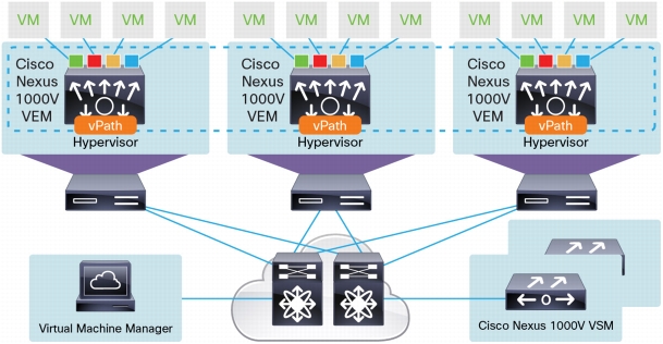
The Cisco Nexus 1000V Series provides Layer 2 switching, advanced networking functions, and a common network management model in a virtualized server environment by replacing the virtual switch within VMware vSphere. As Figure 1 shows, the Cisco Nexus 1000V Series Switches manage a data center as defined in VMware vCenter Server. Each server in the data center is represented as a line card in the Cisco Nexus 1000V Series Switch and can be managed as if it were a line card in a physical Cisco switch.
The Cisco Nexus 1000V Series implementation has two main components:
• Virtual supervisor module (VSM)
• Virtual Ethernet module (VEM)
Figure 1. Cisco Nexus 1000V Series Architecture
The benefits of deploying the Cisco Nexus 1000V Series are:
• Operation simplicity and efficiency, with the network administrator managing the virtual access layer using existing tools
• Advanced networking capabilities, such as quality of service (QoS), network statistics collection with Cisco NetFlow Collector, packet mirroring with Cisco Encapsulated Remote Switched Port Analyzer (ERSPAN), and many others
• Nondisruptive operating model, with Cisco Nexus 1000V Series Switches fully integrated into VMware vCloud Director and vCenter Server
• Easier regulatory compliance of applications in the cloud because there is complete transparency in both the physical and virtual networks
Overview of Cisco Nexus 1000V VXLAN
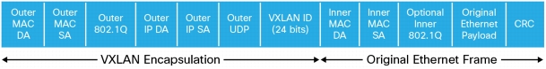
VXLAN is a Layer 2 network isolation technology that uses a 24-bit segment identifier to scale beyond the 4000-address limitations of VLANs. VXLAN technology creates LAN segments by using an overlay approach with MAC-in-IP encapsulation. The Cisco Nexus 1000V VEM encapsulates the original Layer 2 frame leaving the virtual machine (Figure 2).
Figure 2. VXLAN Encapsulated Frame Format
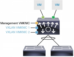
Each VEM is assigned an IP address, which is used as the source IP address when encapsulating MAC address frames to be sent on the network. This assignment is accomplished by creating VMkernel network interface cards (VMKNICs) on each VEM (Figure 3). You can have multiple VMKNICs per VEM that are used as sources for this encapsulated traffic. The encapsulation carries the VXLAN identifier, which is used to scope the MAC address of the payload frame.
Figure 3. VEM VMKNIC Interface with VXLAN Capability
The connected VXLAN is specified in the port-profile configuration of the virtual NIC (vNIC) and is applied when the virtual machine connects.
The original implementation of VXLAN in the Cisco Nexus 1000V Series relies on IP multicast to deliver broadcast, unknown unicast, and multicast (BUM) traffic to all hosts in the same VXLAN domain. Each VXLAN uses an assigned IP multicast group to carry broadcast traffic within the VXLAN segment.
Some organizations prefer not to implement IP multicast in their physical networks. To bring VXLAN to such customers, Cisco introduced Enhanced VXLAN. In this mode, the Cisco VEM running on the VMware ESX host intelligently sends the BUM traffic to all other VEMs that have virtual machines in the VXLAN.
The Cisco Nexus 1000V VXLAN Gateway is deployed as a virtual services blade (VSB) on the Cisco Nexus 1100 or 1010 Series Cloud Services Platform. This includes the 1010, 1010-X, 1110-S and 1110-X platforms. For the remainder of the document we will refer to the appliance as the Cisco Nexus Cloud Services Platform to cover all four types.
The Cisco Nexus 1110 and 1010 appliances offer physical platforms for deployment and management of the Cisco Nexus 1000V VSMs and other virtual services. The platform consists of the physical server coupled with the Cisco Cloud Services Platform (CSP) manager software, which houses multiple Cisco VSBs.
The Cisco Nexus 1110-S can host up to 10 VSBs, and the Cisco Nexus 1110-X can host up to 14 VSBs. The Cisco Nexus 1010-S can host up to 6 VSBs, and the Cisco Nexus 1010-X can host up to 10 VSBs. There are 6 uplinks available on the 1010 and 1110 Cloud Services Platform.
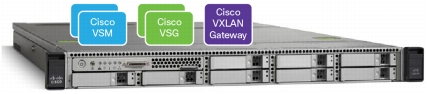
These VSBs can be any combination of the VSBs supported within the resource limits mentioned above. Figure 4 shows an example of a configuration.
Figure 4. Cisco Nexus 1100 Series Cloud Services Platform with Three VSBs: Cisco VSM, Virtual Services Gateway (VSG), and VXLAN Gateway
Cisco Nexus Cloud Services Platform Passthrough
The VXLAN Gateway VSB on the Cisco Nexus Cloud Services Platform uses the passthrough capability introduced in Cisco Nexus Cloud Services Platform Software Release 4.2(1)SP1(6.1). The passthrough capability allows a VSB to assign a virtual interface to a dedicated uplink, which can be a Gigabit Ethernet port on the Cisco Nexus 1010 or 1110 hardware or a PortChannel. A passthrough uplink is not shared with any other virtual interface, neither on the same VSB or a different one.
The passthrough feature provides the following benefits to a VSB:
• Passthrough bypasses Linux bridging and bonding, resulting in lower latency.
• Because the passthrough uplinks are not shared, the VSB can have dedicated bandwidth.
• VSBs can support trunk interfaces in promiscuous mode and receive VLAN tagged packets.
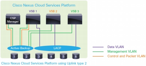
Figure 5 shows the traditional networking model on the Cisco Nexus Cloud Services Platform, in which an uplink is shared between multiple VSBs. In a typical shared uplink, a packet traverses a few layers of Linux bonding and bridging before it reaches the virtual interface. In addition, the VSB interface can be configured only as an access port; trunk interfaces are not supported. Shared networking is supported with all network uplink types.
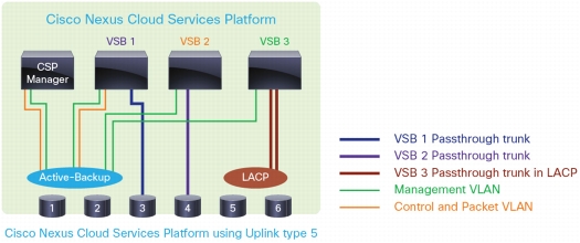
Figure 6 shows the passthrough networking model on the Cisco Nexus Cloud Services Platform in which an uplink is dedicated to a VSB and can be configured as a trunk interface to support tagged packets. A VSB can have some interfaces in shared mode and some in passthrough mode. Passthrough networking is supported only with uplink type 5 on the Cisco Nexus Cloud Services Platform.
Figure 6. Cisco Nexus 1100 Series Passthrough Networking
VXLAN Gateway
Overview of VXLAN Gateway
The current support for VXLAN extends to virtual switches that run in a hypervisor environment, and the only endpoints that can be on VXLANs are virtual machines. Physical servers and traditional service nodes will continue to be used on traditional VLAN interfaces. To connect workloads with some components on a VXLAN interface and others on a VLAN interface, or to apply hardware-based services to a VXLAN network, an interconnection mechanism is needed.
One way to interconnect VXLANs and traditional VLANs is through a virtual machine-based software router such as the Cisco ASA 1000V. The ASA 1000V is a Layer 3 gateway, and VXLAN traffic is routed through the Cisco ASA 1000V, which will have one interface on a VXLAN segment and another on a VLAN segment.
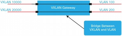
The VXLAN Gateway provides a way to connect a VXLAN segment to a VLAN segment at Layer 2. A logical instance of this gateway is a 2-port Layer 2 learning bridge that connects a particular VXLAN segment to an IEEE 802.1Q VLAN (Figure 7).
Figure 7. VXLAN Gateway Conceptual View
VXLAN Gateway Deployment
Cisco Nexus 1000V Series Release 4.2(1)SV2(2.1) is the first release that supports the VXLAN Gateway. In this release, the VXLAN Gateway is deployed as a VSB on the Cisco Nexus Cloud Services Platform. The VXLAN Gateway is configured and managed through a Cisco Nexus 1000V VSM. When a VXLAN Gateway VSB is created, the VSM information is configured as part of the initial setup. The VXLAN Gateway is then registered as a service module on the Cisco Nexus 1000V VSM that is controlling it. Each Cisco Nexus 1000V VSM can support a total of four VXLAN Gateway clusters, a cluster is comprised of two VXLAN Gateway instances in an HA pair.
The VXLAN Gateway is always controlled and managed from a single Nexus 1000V VSM. However, the traffic reaching the VXLAN Gateway could be originated from any physical or virtual switch.
The communication between the Cisco Nexus 1000V VSM and the VXLAN Gateway follows the same principles as VSM-to-VEM communication. The only supported mode is Layer 3 communication using either the management or control interface on the VSM. Use of the management interface on the Cisco Nexus 1000V VSM is strongly recommended for Layer 3 control.
The primary and secondary VXLAN Gateway VSBs are configured with individual IP addresses during VSB configuration. These IP addresses are used as the endpoints for Layer 3 control communication with the Cisco Nexus 1000V VSM.
VXLAN Gateway deployment requires the Cisco Nexus 1000V switch to be configured to use the Advanced mode licenses.
VXLAN Gateway Interfaces
The VXLAN Gateway VSB has three interfaces that must be configured before enabling the VSB:
• Management interface: The management interface is used for communication between the VXLAN Gateway and the Cisco Nexus 1000V VSM.
• Gateway uplinks 1 and 2: Gateway uplinks 1 and 2 are used for data traffic on the VXLAN Gateway. These interfaces are always configured as a PortChannel in Link Aggregation Control Protocol (LACP) mode and require the upstream switch to support LACP or static PortChannels. These interfaces use the passthrough capability provided by the Cisco Nexus Cloud Services Platform. Gateway uplinks 1 and 2 are configured as trunk ports, and the VLANS that must be allowed are the VXLAN transport VLAN and the VLANS that map to VXLAN segments on the VXLAN Gateway.
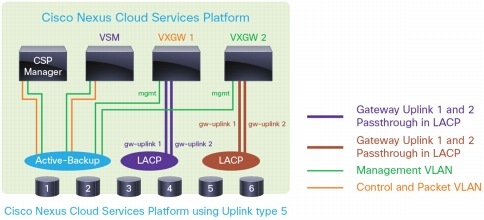
Figure 8 shows how the VXLAN Gateway is typically deployed on the Cisco Nexus Cloud Services Platform. Because each VXLAN Gateway requires two passthrough interfaces, a maximum of 2 VXLAN Gateway VSBs can be supported on one Cisco Nexus Cloud Services Platform pair. In this example, the VXLAN Gateway shares the management interface with the Cisco CSP manager and the VSM.
The VXLAN Gateway VSBs can be configured as a pair of gateway modules that operate together as a single high-availability module. You should always deploy the VXLAN gateway in a high-availability configuration. During VSB deployment, the Cisco CSP manager automatically deploys primary and secondary VXLAN Gateway VSBs when the enable command is entered in Cisco VSB configuration mode. After deployment, the cluster configuration and active and standby roles for each gateway in the cluster are configured on the Cisco Nexus 1000V VSM that control the VXLAN Gateway.
At any given time, only one gateway module for a given cluster actively performs the gateway function. The other gateway module stays in the standby state pending the failure of the active module. When the standby gateway detects that the active gateway has failed, it transitions to the active state and starts performing the gateway functions.
VXLAN Gateway Loop Avoidance
A single Cisco Nexus 1000V VSM can support up to four VXLAN Gateway pairs. In certain scenarios, the same mapping may be applied to multiple VXLAN gateways, resulting in a traffic loop. Examples of such scenarios include:
• Split-brain state: Both VXLAN Gateways in a high-availability pair think that they are active.
• Configuration error: The same mapping is configured on multiple VXLAN Gateways.
The VXLAN Gateway has a built-in mechanism to detect and warn the user about potential loops in the network If a loop is detected, a syslog is generated to alert the user. The user can then use the attach vem N command to attach to the VXLAN Gateway and execute vemcmd show vxlan-gw-mappings to view the state of the mappings.
VXLAN Gateway Deployment Use Cases
The most common deployment use cases for VXLAN Gateway are discussed here. In general, a VXLAN Gateway is used to bridge traffic between a VXLAN segment and a traditional VLAN segment. The important point to note while deploying a VXLAN Gateway is that it operates at Layer 2, and all workloads connected through a VXLAN Gateway are considered to be in the same Layer 2 domain.
Use Case 1: Connect Virtual and Physical Workloads in the Same Layer 2 Segment
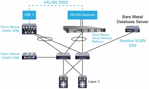
• In the case of multitier applications that are being virtualized, some tiers of the application may still be on physical servers. In the example in Figure 9, a virtualized web server is connecting through the VXLAN Gateway to a database server that is on a bare-metal host. In this example, the VXLAN Gateway is mapping VXLAN 5500 to VLAN 550.
Figure 9. Virtualized Web Server on VXLAN Connecting to Bare-Metal Database Server
Use Case 2: Connect Physical Services to Virtual Workloads
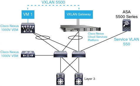
Data center services such as load balancers, firewalls, and WAN accelerators can be deployed in virtual or physical form factors in a virtualized data center. Services deployed in a physical form factor are not VXLAN aware; they may reside on standalone bare-metal servers or be deployed as service modules on access switches. The VXLAN Gateway can be deployed to connect virtualized workloads on a VXLAN segment to a traditional service node on a VLAN. In the example in Figure 10, a virtual machine on VXLAN 5500 is connecting through the VXLAN gateway to a physical Cisco ASA 5500 Series firewall on VLAN 550.
Figure 10. Virtualized Workloads on VXLAN Connecting to Cisco ASA 5500 Physical Firewall
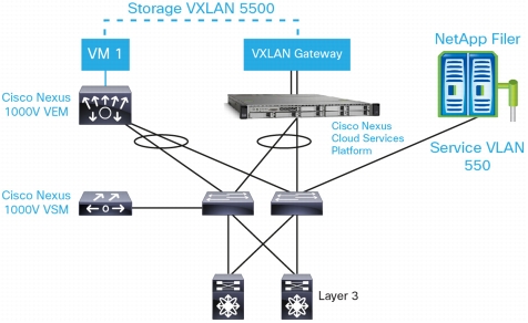
Use Case 3: Connect Virtual Machines on VXLAN to Physical Storage
Virtual machines on a VXLAN segment can be configured to access SAN or NAS devices that are on a VLAN segment. In the example in Figure 11, a virtual machine is accessing a NetApp Filer through the VXLAN Gateway.
Figure 11. Accessing a NetApp Filer Through the VXLAN Gateway
Deployment Considerations
Cisco Nexus 1000V Series Deployment
Standard best practices for VSM deployments should be followed. The VSM can be part of the same cluster in VMware vCenter for which it is providing Layer 2 networking functions. The VSM can also be hosted on the Cisco Nexus 1110 appliance that is running the VXLAN Gateway. In addition, the following configuration must be applied to the VSM:
• Verify that the VSM is configured in the Advanced mode by entering the svs switch edition advanced command to enable Advanced mode.
• Verify that LACP is configured by entering the feature lacp command on the VSM.
• Verify that the VXLAN feature is enabled on the VSM by entering the feature segmentation command to enable VXLANs on the VSM.
VXLAN Using Multicast or Unicast
The VXLAN Gateway will work with traditional deployments running multicast for broadcast, multicast, and unicast traffic as well as with Enhanced VXLAN which does not require multicast for BUM traffic.
Cisco Nexus Cloud Services Platform Virtual Service Blade Resource Requirements
Each instance of the VXLAN Gateway VSB will be allocated three cores and 2 GB of RAM. The VXLAN Gateway VSB also requires two physical ports on the Cisco Nexus Cloud Services Platform that must be configured in passthrough mode and cannot be shared. The management interface can share the ports used for the control and management of the Cisco Nexus CSP manager or other VSBs. The requirement for the two dedicated passthrough ports translates into the capability to deploy a maximum of two VXLAN Gateways in a high-availability pair on one Cisco Nexus Cloud Services Platform pair.
Scalability of VXLAN Gateway
A single instance of a VXLAN Gateway can support up to 512 mappings. To support more mappings, additional gateways can be deployed. The maximum number of gateways that can be managed by a VSM is 4, for a total of 2048 mappings.
Deployment Example: Connect Virtual and Physical Workloads in the Same Layer 2 Segment
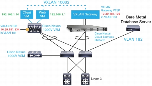
The example illustrated in Figure 12 deploys a web development virtual application (vApp) that consists of three virtual machines: web, database, and Microsoft Windows client. The web server and Microsoft Windows client are virtual machines on VXLAN segment 10082, and the database server is a bare-metal host on VLAN 182. The VXLAN Gateway is deployed as a VSB on the Cisco Nexus Cloud Services Platform and provides a mapping from VXLAN 10082 to VLAN 182.
Figure 12. Deploying a Two-Tier Web Development vApp
Note: This document does not discuss the installation and setup of the VMware vSphere environment with Cisco Nexus 1000V Software Release 4.2(1)SV2(2.1) or the installation and setup of the Cisco Nexus Cloud Services Platform Software Release 4.2(1)SP1(6.1) configured to use uplink type 5.
Setting Up the Cisco Nexus 1000V Series for the VXLAN Gateway
The Nexus 1000V VSM that will be controlling the VXLAN Gateway needs to be set up prior to bring up the VXLAN Gateway VSB. Enter the commands shown here at the Cisco Nexus 1000V command-line interface (CLI).
Step 1.Turn on the VXLAN Gateway feature on the Cisco Nexus 1000V Series Switch.
N1KV-VSM(config)# feature vxlan-gateway
Verify that the feature is enabled on the Cisco Nexus 1000V Series Switch.
N1KV-VSM(config)# show feature
Feature Name Instance State
-------------------- -------- --------
cts 1 disabled
dhcp-snooping 1 disabled
http-server 1 enabled
lacp 1 enabled
netflow 1 disabled
network-segmentation 1 disabled
port-profile-roles 1 disabled
private-vlan 1 disabled
segmentation 1 enabled
sshServer 1 enabled
tacacs 1 disabled
telnetServer 1 disabled
vtracker 1 disabled
vxlan-gateway 1 enabled
Step 2.Create a port profile for the VXLAN Gateway trunk interface.
This interface must allow the VLANs used for VXLAN transport as well as the VLANs that are mapped to VXLANs. The mappings from VXLAN to VLAN are configured for this interface and associated with a service instance to segregate mappings. In the example that follows, the mapping is from VXLAN segment 10082, which is in bridge domain tenk82, to VLAN 182. Additional mappings can be configured at any point in this port profile, and they will be pushed to the VXLAN Gateway.
VSM-1# show running-config bridge-domain
!Command: show running-config bridge-domain
!Time: Thu Jun 13 13:43:23 2013
version 4.2(1)SV2(2.1)
feature segmentation
feature vxlan-gateway
bridge-domain tenk82
segment id 10082
segment mode unicast-only
segment distribution mac
<snip>
VSM-1(config)# port-profile type ethernet vxgw-UL
VSM-1(config-port-prof)# switchport mode trunk
VSM-1(config-port-prof)# channel group auto mode active
VSM-1(config-port-prof)#transport ip address 10.29.181.136 255.255.255.0 gateway 10.29.181.1
VSM-1(config-port-prof)# switchport mode access
VSM-1(config-port-prof)# no shutdown
VSM-1(config-port-prof)# state enabled
Step 4.Collect the VSM Information required for VXLAN Gateway configuration.
The domain ID, VSM IP address and VSM primary and secondary MAC addresses are required as input during the activation of the VXLAN Gateway VSB. This information can be obtained by running the following command at the VSM CLI:
VSM-1# show vms internal info
Global svs connection mode: ipv4
Cached IP address: 10.29.173.148
DVS INFO:
-------------
DVS name: [VSM-1]
UUID: [dd 39 00 50 ac ae 1d 81-8e a4 64 47 96 4e ac f7]
Deploying the VXLAN Gateway VSB on the Cisco Nexus Cloud Services Platform
Step 1.Create a new VSB for the VXLAN Gateway.
First, copy the VXLAN Gateway image to the bootflash: repository directory on the Cisco Nexus Cloud Services Platform. Configure a new VSB with the downloaded ISO.
N1010-1# copy scp: bootflash:repository
Enter source filename: <image directory>/vxgw.4.2.1.SV2.2.0.274.iso
N1010-1(config)# virtual-service-blade VXGW1
N1010-1(config-vsb-config)# virtual-service-blade-type new vxgw.4.2.1.SV2.2.0.274.iso
Step 2.Configure the uplinks for the VSB.
The VXLAN Gateway has two interfaces that must be configured in passthrough mode and one management interface. Verify that two free uplinks are available for use by the VXLAN Gateway VSB. The management interface can be shared with the interfaces used for Cisco Nexus CSP management.
Step 5.Verify that the VXLAN Gateway is registered as a service module with the Cisco Nexus 1000V VSM.
The VXLAN Gateway should also be registered with the VSM as a service module. To verify this registration, run the show module command at the Cisco Nexus 1000V CLI.
The Cisco Nexus 1000V VXLAN Gateway enables customers to deploy VXLAN in a mixed environment in which some applications and services are virtualized and can be deployed on VXLAN segments, but there is a need to connect to traditional services that use traditional VLAN-based networking. The VXLAN Gateway operates within a single Layer 2 domain.
This document discussed how to deploy the VXLAN Gateway and configure mappings to send traffic between VXLAN and VLAN segments. The VXLAN Gateway is deployed as a VSB on the Cisco Nexus Cloud Services Platform and managed through a Cisco Nexus 1000V VSM. This document also discussed some common deployment scenarios and explored in detail the setup and configuration of the VXLAN Gateway to connect a web server on a VXLAN segment to a database server on a VLAN segment.
Components
• Cisco Nexus 1000V Virtual Services Module: The Cisco Nexus 1000V Series VSM controls multiple VEMs as one logical modular switch. Instead of physical line-card modules, the VSM supports multiple VEMs running in software inside the physical servers.
• Cisco Nexus 1000V Virtual Ethernet Module: The Cisco Nexus 1000V VEM runs as part of the VMware ESX or ESXi kernel and replaces the VMware virtual switch feature.
• Cisco Nexus Cloud Services Platform: The Cisco Nexus Cloud Services Platform offers a physical platform for deploying and managing the Cisco Nexus 1000V VSMs and other virtual services. The platform consists of the physical server coupled with the Cisco Nexus CSP manager software, which houses multiple Cisco virtual service blades.
• Cisco Nexus 1000V VXLAN Gateway: The Cisco Nexus 1000V VXLAN Gateway is used to interconnect VXLAN and VLAN segments within a Layer 2 domain. It is hosted as a VSB on the Cisco Nexus 1010 and 1110 CSP.
For More Information
For more information about the Cisco Nexus 1000V Series, please refer to the following links: