A virtual PortChannel (vPC) allows links that are physically connected to two different Cisco Nexus™ 5000 Series devices to appear as a single PortChannel to a third device. The third device can be a Cisco Nexus 2000 Series Fabric Extender or a switch, server, or any other networking device. A vPC can provide Layer 2 multipathing, which allows you to create redundancy by increasing bandwidth, enabling multiple parallel paths between nodes and load-balancing traffic where alternative paths exist.
After you enable the vPC function, you create a peer keepalive link, which sends heartbeat messages between the two vPC peer devices.
The vPC domain includes both vPC peer devices, the vPC peer keepalive link, the vPC peer link, and all the PortChannels in the vPC domain connected to the downstream device. You can have only one vPC domain ID on each device.
A vPC provides the following benefits:
• Allows a single device to use a PortChannel across two upstream devices
• Eliminates Spanning Tree Protocol blocked ports
• Provides a loop-free topology
• Uses all available uplink bandwidth
• Provides fast convergence if either the link or a device fails
• Provides link-level resiliency
• Helps ensure high availability
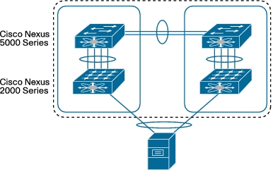
The vPC not only allows you to create a PortChannel from a switch or server that is dual-homed to a pair of Cisco Nexus 5000 Series Switches, but it can also be deployed along with Cisco Nexus 2000 Series Fabric Extenders. The deployment scenario in Figure 1 creates a vPC between the two ports on each of two Cisco® fabric extenders.
Figure 1. vPC with Two Ports from Each of Two Fabric Extenders
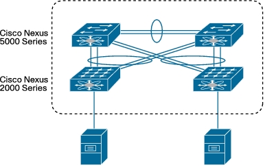
The vPC deployment scenario in Figure 2 allows the Cisco Nexus 2000 Series Fabric Extenders to connect to a pair of Cisco Nexus 5000 Series Switches and make all links active.
Figure 2. vPC with Each Fabric Extender Dual-Connected to Two Cisco Nexus 5000 Series Switches
In addition to the two topologies in Figures 1 and 2, you can use vPC on any device that supports PortChannels, to achieve resilience and high throughput when the device is connected to a pair of Cisco Nexus 5000 Series Switches.
vPC Concepts
The following list defines critical vPC concepts:
• vPC: vPC refers to the combined PortChannel between the vPC peer devices and the downstream device.
• vPC peer switch: The vPC peer switch is one of a pair of switches that are connected to the special PortChannel known as the vPC peer link. One device will be selected as the primary device, and the other will be the secondary device.
• vPC peer link: The vPC peer link is the link used to synchronize states between the vPC peer devices. The vPC peer link carries control traffic between two vPC switches and also multicast, broadcast data traffic. In some link failure scenarios, it also carries unicast traffic. You should have at least two 10 Gigabit Ethernet interfaces for peer links.
• vPC domain: This domain includes both vPC peer devices, the vPC peer keepalive link, and all the PortChannels in the vPC connected to the downstream devices. It is also associated with the configuration mode that you must use to assign vPC global parameters.
• vPC peer keepalive link: The peer keepalive link monitors the vitality of a vPC peer switch. The peer keepalive link sends periodic keepalive messages between vPC peer devices. The vPC peer keepalive link can be a management interface or switched virtual interface (SVI). No data or synchronization traffic moves over the vPC peer keepalive link; the only traffic on this link is a message that indicates that the originating switch is operating and running vPC.
• vPC member port: vPC member ports are interfaces that belong to the vPCs.
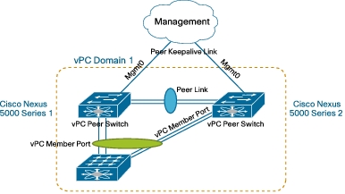
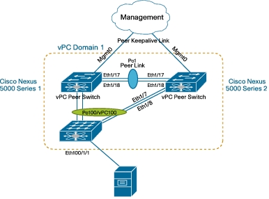
Figure 3 illustrates these concepts.
Figure 3. vPC Concepts
vPC Configuration
vPC configuration on the Cisco Nexus 5000 Series includes these steps:
• Enable the vPC feature.
• Create a vPC domain and enter vpc-domain mode.
• Configure the vPC peer keepalive link.
• (Optional) Configure system priority.
• (Optional) Configure vPC role priority.
• Create the vPC peer link.
• Move the PortChannel to vPC.
Table 1 provides details about these steps.
Table 1. vPC Configuration Steps
Command
Purpose
Step 1
configure t
Enter the global configuration mode.
Step 2
feature vpc
Example:
switch(config)feature vpc
Enable the vPC feature. The vPC feature must be enabled before it can be configured
Configure the IPv4 address for the remote end of the vPC peer keepalive link.
The system does not create the vPC peer link until you configure a vPC peer keepalive link.
The Cisco Nexus 5000 Series does not support creation or configuration of additional Virtual Route Forwarding (VRF) instances. Two VRF instances are created when the system boots: management and default. The management interface is in the VRF management instance, and all SVIs are in the VRF default instance.
Both management interfaces and SVIs can be used for peer keepalive links. The management interface and VRF management instance are the defaults.
The second example shows how to configure the SVI as the keepalive link. The source address must be specified when the VRF default instance is used for peer keepalive communication.
Step 5
system-prioritypriority
Example:
switch(config-vpc-domain)# system-priority 4000
switch(config-vpc-domain)#
(Optional) Enter the system priority that you want for the specified vPC domain. The range of values is 1 to 65535. The default value is 32667.
You should manually configure the vPC system priority when you are running Link Aggregation Control Protocol (LACP) to help ensure that the vPC peer devices are the primary devices on LACP. When you manually configure the system priority, make sure that you configure the same priority value on both vPC peer devices. If these values do not match, vPC will not be activated.
Step 6
role prioritypriority
Example:
switch(config-vpc-domain)# role priority 2000
switch(config-vpc-domain)#
(Optional) Enter the role priority that you want for this vPC switch. The range of values is 1 to 65636, and the default value is 32667.
The switch with lower priority will be elected as the vPC primary switch. If the peer link fails, vPC peer will detect whether the peer switch is alive through the vPC peer keepalive link. If the vPC primary switch is alive, the vPC secondary switch will suspend its vPC member ports to prevent potential looping while the vPC primary switch keeps all its vPC member ports active.
Step 7
interface port-channelchannel-number
vpc peer-link
Example:
switch(config)# interface port-channel 20
switch(config-if)# vpc peer-link
Select the PortChannel that you want to use as the vPC peer link for this device, and enter the interface configuration mode.
Configure the selected PortChannel as the vPC peer link.
Step 8
interface port-channelchannel-number
vpcnumber
Example:
switch(config)#interface e1/1
switch(config-if)channel-group 20
switch(config-if)# interface port-channel 20
switch(config-if)# vpc 100
Add the interface to the PortChannel and then move the PortChannel to the vPC to connect to the downstream device. The vPC number ranges from 1 to 4096. The vPC number does not need to match the PortChannel number, but it must match the number of the vPC peer switch for that vPC bundle.
A PortChannel is needed even if there is only one member interface for the PortChannel. When there is only one member for the PortChannel, the hardware PortChannel resource will not be created.
vPC Configuration Examples
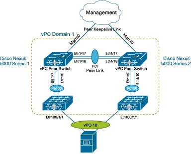
Following are the steps to configure vPC on Cisco 5000 Series Switch 1 shown in Figure 4.
Figure 4. vPC Configuration Example: vPC with Two Ports from Two Fabric Extenders
Step 1. Configure the management interface IP address and default route.
N5k-1(config)# int mgmt 0
N5k-1(config-if)# ip address 172.25.182.51/24
N5k-1(config-if)# vrf context management
N5k-1(config-vrf)# ip route 0.0.0.0/0 172.25.182.1
Step 2. Enable vPC and LACP.
N5k-1(config)# feature vpc
N5k-1(config)# feature lacp
Step 3. Create a VLAN.
N5k-1(config)#vlan 101
Step 4. Create the vPC domain.
N5k-1(config)# vpc domain 1
Step 5. Configure the vPC role priority (optional).
N5k-1(config-vpc-domain)# role priority 1000
Step 6. Configure the peer keepalive link. The management interface IP address for Cisco Nexus 5000 Series Switch 2 is 172.25.182.52.
--------:: Management VRF will be used as the default VRF ::--------
Step 7. Configure the vPC peer link. Note that, as for a regular interswitch trunk, trunking must be turned on for the VLANs to which the vPC member port belongs.
N5k-1(config-vpc-domain)# int ethernet 1/17-18
N5k-1(config-if-range)# channel-group 1 mode active
Step 8. Configure the Cisco Nexus 2000 Series Fabric Extenders and the fabric interface.
N5k-1(config)# fex 100
N5k-1(config-fex)# pinning max-links 1
Change in Max-links will cause traffic disruption.
N5k-1(config-fex)# int e1/7-8
N5k-1(config-if-range)# channel-group 100
N5k-1(config-if-range)# int po100
N5k-1(config-if)# switchport mode fex-fabric
N5k-1(config-if)# fex associate 100
Step 9. Move the fabric extender interface to vPC. After fabric extender 100 (fex 100) comes online, create the PortChannel for interface eth100/1/1 and move the PortChannel to the vPC. Note that the PortChannel number and vPC number can be different, but the vPC number must be the same on both Cisco Nexus 5000 Series Switches.
N5k-1(config-if)# int ethernet 100/1/1
N5k-1(config-if)# channel-group 10
N5k-1(config-if)# int po10
N5k-1(config-if)# vpc 10
N5k-1(config-if)# switchport access vlan 101
The configuration steps for the second switch, Cisco Nexus 5000 Series Switch 2, are:
N5k-2(config)# int mgmt 0
N5k-2(config-if)# ip address 172.25.182.52/24
N5k-2(config-if)# vrf context management
N5k-2(config-vrf)# ip route 0.0.0.0/0 172.25.182.1
Change in Max-links will cause traffic disruption.
N5k-2(config-fex)# int e1/9-10
N5k-2(config-if-range)# channel-group 100
N5k-2(config-if-range)# int po100
N5k-2(config-if)# switchport mode fex-fabric
N5k-2(config-if)# fex associate 100
N5k-2(config-if)# int ethernet 100/1/1
N5k-2(config-if)# channel-group 10
N5k-2(config-if)# int po10
N5k-2(config-if)# vpc 10
N5k-2(config-if)# switchport access vlan 101
For the deployment scenario in Figure 5, the fabric extender is dual-connected to a pair of Cisco Nexus 5000 Series Switches. Most vPC-related configuration steps are the same as in the previous example, except that the fabric interfaces on the Cisco Nexus 5000 Series Switches will be moved to the vPC rather than to the fabric extender host interface.
Figure 5. vPC Configuration Example: Fabric Extender Dual-Connected to Cisco Nexus 5000 Series Switches
N5k-1(config-fex)# int e1/7-8
N5k-1(config-if-range)# channel-group 100
N5k-1(config-if-range)# int po100
N5k-1(config-if)# vpc 100
N5k-1(config-if)# switchport mode fex-fabric
N5k-1(config-if)# fex associate 100
Verifying the vPC Configuration
Use the commands in Table 2 to display vPC configuration information.
Table 2. Commands for Verifying vPC Configuration
Command
Purpose
show feature
Reports whether or not vPC is enabled
show vpc brief
Displays brief information about the vPCs
show vpc consistency-parameters
Displays the status of those parameters that must be consistent across all vPC interfaces
show running-config vpc
Displays running configuration information for vPCs
show port channel capacity
Reports the number of PortChannels that are configured and the number that are still available on the device
show vpc statistics
Displays statistics about the vPCs
show vpc peer-keepalive
Displays information about the peer keepalive messages
show vpc role
Displays the peer status, role of the local device, vPC system MAC address and system priority, and MAC address and priority for the local vPC device
vPC Configuration Compatibility Checking
Many configuration and operational parameters must be identical on all interfaces in the vPC. You should configure the Layer 2 PortChannels that you use for the vPC peer link in trunk mode.
After you enable the vPC feature and configure the peer link on both vPC peer devices, Cisco Fabric Services messages provide a copy of the configuration on the local vPC peer device to the remote vPC peer device. The system then determines whether any of the crucial configuration parameters differ on the two devices.
Enter the show vpc consistency-parameters command to display the configured values on all interfaces in the vPC. The displayed configurations are only those configurations that would prevent the vPC peer link and vPC from operating.
There are two different types of configuration parameters from a vPC compatibility perspective. The first type of parameters must be identical on both vPC switches, and any difference will prevent the vPC peer link or vPC from functioning. The configuration of the second type of parameters should be identical on both switches; any differences in these parameters will result in undesired behavior.
Configuration Parameters That Must Be Identical
The configuration parameters listed in this section must be configured identically on both devices of the vPC peer link or the vPC will enter suspend mode. The devices automatically check for compatibility of some of these parameters on the vPC interfaces. The per-interface parameters must be consistent per interface, and the global parameters must be consistent globally.
• PortChannel mode
– On, off, or active
• Link speed per PortChannel
• Duplex mode per PortChannel
• Trunk mode per PortChannel
– Native VLAN
• Spanning Tree Protocol mode
• Spanning Tree Protocol region configuration for Multiple Spanning Tree (MST) Protocol
• Enable or disable state per VLAN
• Spanning Tree Protocol global settings
– Bridge assurance setting
– Port type setting (you should set all vPC interfaces as network ports)
– Loop guard settings
• Spanning Tree Protocol interface settings
– Port type setting
– Loop guard
– Root guard
• Quality of service (QoS) configuration and parameters
– Priority flow control (PFC)
– Strict priority queuing and deficit weighted round robin (DWRR)
– Maximum transmission unit (MTU)
If any of these parameters are not enabled or defined on either device, the vPC consistency check ignores those parameters.
Configuration Parameters That Should Be Identical
When any of the following parameters are not configured identically on both vPC peer devices, a misconfiguration may cause undesirable behavior in the traffic flow:
• MAC address aging timers
• Static MAC address entries
• All access control list (ACL) configurations and parameters
• Spanning Tree Protocol interface settings
– Bridge Protocol Data Unit (BPDU) filter
– BPDU guard
– Cost
– Link type
– Priority
– VLANs (Rapid Per-VLAN Spanning Tree Plus [PVST+])
• Internet Group Management Protocol (IGMP) snooping
To ensure that all the configuration parameters are compatible, you should display the configuration information for each vPC peer device after you configure the vPC.