The data center is rapidly moving to the era of the cloud. Private clouds are widely deployed, and organizations are looking to public clouds to expand their infrastructure to take advantage of the elasticity and cost advantages that public clouds provide. To gain the benefits of a public cloud but retain the security, management, and control of a private cloud, customers are moving toward hybrid cloud models.
Although the public cloud offers several advantages, such as reduced operating and infrastructure costs, rapid application provisioning, and abundant availability of resources, it poses some challenges that are preventing enterprises from fully harnessing the power of the public cloud and integrating public clouds with their private clouds. Some of the main concerns slowing adoption of hybrid clouds are:
• Security concerns about applications running in a public provider environment, including lack of enterprise control and monitoring
• The need to redesign applications to migrate them from a private or hosted data center to a provider cloud
• The need to redesign services and policies to uses the services offered by cloud providers
• Inconsistent operating models and tools across cloud providers
• Inability to move workloads between cloud providers, leading to vendor lock-in
Cisco Nexus® 1000V InterCloud provides a hybrid cloud solution that addresses these challenges and accelerates the adoption of hybid clouds. Using Cisco Nexus 1000V InterCloud, an enterprise can securely extend its data center to the public cloud. A secure Layer 2 extension enables data center center applications and services to run in a public cloud environment as if they were on the private enterprise data center network. All data traversing the system is cryptographically isolated and secured using keys that are generated and managed within the enterprise.
This document provides guidelines for deploying Cisco Nexus 1000V InterCloud. Common use cases and deployment scenarios for Cisco Nexus 1000V InterCloud are discussed.
For detailed configuration documentation, please refer to the respective Cisco® product configuration guides found on http://www.cisco.com. You can find links to the product configuration guides and other related deployment guides in the For More Information section of this document.
Audience
This document is intended for network architects, network engineers, and cloud administrators interested in deploying a hybrid cloud solution using Cisco Nexus 1000V InterCloud.
Background
Cisco Nexus 1000V Series Switches
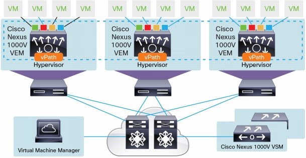
Cisco Nexus 1000V Series Switches provide Layer 2 switching, advanced networking functions, and a common network management model in a virtualized server environment by replacing the virtual switch within a hypervisor. As Figure 1 shows, the Cisco Nexus 1000V Series Switches manage a data center. Each server in the data center is represented as a line card in the Cisco Nexus 1000V Series virtual switch and can be managed as if it were a line card in a physical Cisco switch.
The Cisco Nexus 1000V Series implementation has two main components:
• Virtual Supervisor Module (VSM)
• Virtual Ethernet module (VEM)
Figure 1. Cisco Nexus 1000V Series Switch Architecture
Virtual Supervisor Module
The VSM provides the management-plane functions for the Cisco Nexus 1000V Series. Unlike a traditional Cisco switch, in which the management plane is integrated into the hardware, on the Cisco Nexus 1000V Series, the VSM is deployed as either a virtual appliance on a hypervisor or as a virtual service blade on the Cisco Cloud Services Platform. The VSM is usually deployed in a high-availability pair, with one VSM functioning as the primary supervisor and the other VSM functioning as the secondary supervisor. When the primary VSM fails, the secondary VSM takes over as the primary supervisor.
Virtual Ethernet Module
The VEM provides the Cisco Nexus 1000V Series with network connectivity and forwarding capabilities much like a line card in a modular switching platform. Unlike multiple line cards in a single chassis, each VEM acts as an independent switch from a forwarding perspective. The VEM is tightly integrated with the hypervisor on which it runs. A pair of VSMs managing one or more VEMs comprise a single Cisco Nexus 1000V Series Switch instance.
The communication between the VSM and VEM can be in Layer 2 mode, if the VSM and VEMs are in the same Layer 2 domain, or in Layer 3 mode. Layer 3 mode is the recommended mode for VSM-to-VEM communication.
Overview of Cisco Nexus 1000V InterCloud
Cisco Nexus 1000V InterCloud is built on the proven infrastructure of the Cisco Nexus 1000V Series distributed virtual switches (DVSs). It is managed and operated by the Cisco Prime™ Network Services Controller (NSC), which is also used to manage virtualized services deployed with Cisco Nexus 1000V Series.
Cisco Nexus 1000V InterCloud version 5.2(1)IC1(1.1) provides the following capabilities:
• Secure network extension from a private data center network to Amazon Web Services (AWS)
• Integration with VMware vCenter Versions 5.0 and 5.1 to view enterprise virtual machine inventory and migrate enterprise applications and templates to AWS
• Single pane of management for all virtual machines in Cisco Nexus 1000V InterCloud, including virtual machine creation, deletion, and cloning
• Advanced Cisco Nexus 1000V Series switching features such as access control lists (ACLs) and Internet Group Management Protocol (IGMP) for applications running in the public cloud
Cisco Nexus 1000V InterCloud version 5.2(1)IC1(1.2) provides the following additional capabilities:
• Additional switching features - Netflow and ACL logging
• Experimental vPath support allowing for PoC deployments illustrating the use of Cisco Virtual Security Gateway to protect cloud Virtual Machines
• Enhanced user experience for uploading platform images and InterCloud Agent images to Cisco Prime NSC
Cisco Nexus 1000V InterCloud consists of the following infrastructure components:
• Cisco Prime NSC: Single pane for management of Cisco Nexus 1000V InterCloud
• InterCloud virtual switch: DVS that spans enterprise and provider clouds
• InterCloud Agent (ICA): Image that runs on every cloud virtual machine to provide support for multiple network interface cards (NICs) and encryption support
Cisco Prime Network Services Controller
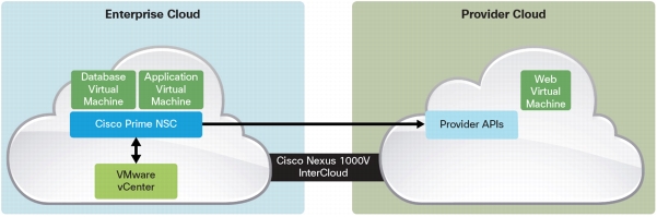
The Cisco Prime NSC (Figure 2) provides single-pane management of Cisco Nexus 1000V InterCloud. It integrates with the virtual machine manager in the enterprise and is also integrated with the cloud provider through well-known APIs. Cisco Prime NSC is deployed as an OVA file in VMware vCenter.
In the first release of Cisco Nexus 1000V InterCloud, Cisco Prime NSC integrates with VMware vCenter Version 5.0 or 5.1 on the enterprise side, and with AWS on the provider side. Future releases will add support for additional virtual machine managers and providers.
Figure 2. Cisco Prime Network Services Controller
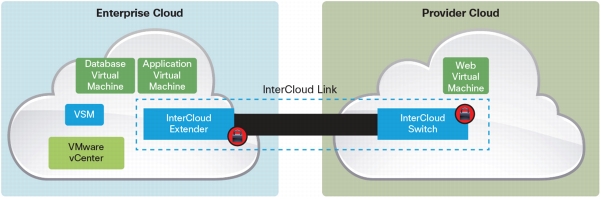
InterCloud Virtual Switch
The InterCloud virtual switch is made up of a VSM and an InterCloud Link. The InterCloud Link is a secure tunnel that is formed between a pair of virtual machines: the InterCloud Extender running in the enterprise, and the InterCloud Switch running in AWS.
InterCloud Virtual Supervisor Module
The InterCloud VSM is similar to the Cisco Nexus 1000V Series VSM, but is used only to configure networking and services for virtual machines in the provider cloud. The enterprise data center can run a Cisco Nexus 1000V Switch or any other virtual switch or DVS. The Cisco Nexus 1000V InterCloud software package includes the VSM image to be used with Cisco Nexus 1000V InterCloud. The Cisco Nexus 1000V InterCloud VSM image is currently different from the Cisco Nexus 1000V Series VSM image.
InterCloud Link
The InterCloud Link consists of the InterCloud Extender (ICX) virtual machine, the InterCloud Switch (ICS) virtual machine, and the secure tunnel that connects the InterCloud Extender and InterCloud Switch. An InterCloud Link is configured through the Cisco Prime NSC web interface. This configuration automatically triggers the creation of the InterCloud Extender and InterCloud Switch virtual machines and the establishment of a secure tunnel between them. The InterCloud Extender and InterCloud Switch register with the InterCloud VSM as service modules and are managed like VEMs. A single VSM can manage up to eight InterCloud Links deployed in a high-availability configuration.
InterCloud Extender
The InterCloud Extender is deployed as a virtual machine in VMware vCenter. The InterCloud Extender can be deployed manually or automatically through Cisco Prime NSC while creating an InterCloud Link. You always should deploy the InterCloud Extender automatically through Cisco Prime NSC. The InterCloud Extender is the endpoint for the secure tunnel from the provider to the enterprise. Additionally, it is the entity that enables the extension of the enterprise network to the public cloud.
InterCloud Switch
The InterCloud Switch (Figure 3) is deployed as a virtual machine in the provider environment. When Amazon is the provider, the InterCloud Switch image is an Amazon Machine Image (AMI) that is uploaded to AWS and deployed through Cisco Prime NSC during creation of an InterCloud Link. The InterCloud Switch is the endpoint for the secure tunnel on the provider side. It is also the secure tunnel endpoint for the virtual machines running in the cloud. All traffic that is sent, both from the enterprise to the provider and between virtual machines in the public cloud, goes through the InterCloud Switch.
The virtual machines in the provider cloud must run an InterCloud Agent image to be part of the Cisco Nexus 1000V InterCloud solution. When a virtual machine migrates from the enterprise or when a template is copied from the enterprise to the provider cloud, Cisco Prime NSC automatically adds the InterCloud Agent image to the virtual machine. The InterCloud Agent is dependent on the OS and version of the virtual machine. The supported OS types are:
• Red Hat Enterprise Linux (RHEL) 6.0, 6.1, 6.2, and 6.3 (64-bit and 32-bit versions)
• CentOS 6.3 (64-bit and 32-bit versions)
• Microsoft Windows 2008 R2 (Service Pack 1 [SP1]) with AMI and VMware Virtual Machine Disk (VMDK) templates
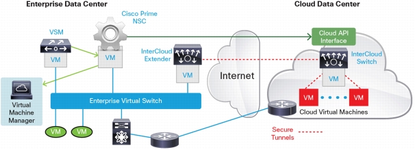
Cisco Nexus 1000V InterCloud Component Interfaces
Figure 4 shows the main components of the Cisco Nexus 1000V InterCloud solution architecture. Specific communication needs exist between the components, and the following sections describe the interfaces on each component and how they are used for communication with other interfaces in the system.
The Cisco Prime NSC has a single management interface that is used for web and Secure Shell (SSH) access. The management interface must have a connection to the public Internet to reach the provider. Specifically, the management interface is used for communication with the following components:
• VSM
• VMware vCenter
• InterCloud Extender
• InterCloud Switch
• AWS (requires a public IP address through Network Address Translation [NAT] Port Address Translation [PAT])
• Cloud virtual machines (requires a public IP address through NAT or PAT)
InterCloud Virtual Supervisor Module
The InterCloud VSM, similar to the Cisco Nexus 1000V Series VSM, runs the control plane for the InterCloud virtual switch. The InterCloud VSM always runs in Layer 3 control mode. The InterCloud Extender and InterCloud Switch register as service modules in the InterCloud VSM and are displayed in the show module output.
The InterCloud VSM has the same three interfaces - control, packet, and management - as the Cisco Nexus 1000V Series VSM:
• Control interface
– Used for communication between active and standby VSMs
• Management interface
– Used to connect to the command-line interface (CLI) of the InterCloud VSM using SSH
– Used for communication with Cisco Prime NSC
• Always used as the source interface for Layer 3 control communication with the InterCloud Extender and InterCloud Switch
• Packet interface
– Not used because only Layer 3 communication is supported for InterCloud VSM
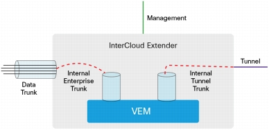
InterCloud Extender
The InterCloud Extender (Figure 5) is the endpoint for the secure tunnel from the provider to the enterprise and provides the network extension for VLANs in the enterprise. The InterCloud Extender has three external interfaces and two internal interfaces:
• Data trunk interface
– This trunk interface carries all the VLANs that need to be extended to the public cloud. This interface is configured with a port profile on the enterprise VSM or with a VMware port group. The VLANs carried in this VLAN must match the VLANs configured on the Internal tunnel trunk and Internal enterprise trunk interface.
– The trunk interface operates in promiscuous mode. All broadcast, multicast, and unknown unicast traffic is sent over the secure tunnel to reach the virtual machines in the public cloud.
• Management interface
– This interface is used to connect to the CLI of the InterCloud Extender using SSH.
– Cisco Prime NSC uses this interface to configure the InterCloud Extender.
– This interface is used as the source interface for Layer 3 control communication with the VSM.
– This interface can be used as the tunnel endpoint for the secure tunnel with the InterCloud Switch. If the management interface is used as the tunnel endpoint, it must have a public IP address.
• Tunnel interface
– This optional interface can be used as the tunnel endpoint for a secure tunnel with the InterCloud Switch.
– This interface is used to keep the management network private. The tunnel interface needs to have access to the Internet either through NAT or PAT or a direct public IP address.
• Internal enterprise trunk interface
– This interface is used to trunk the VLANs on the data trunk interface to the embedded VEM in the InterCloud Extender.
– By default, this interface is assigned the port profile N1K_Cloud_Default_Trunk, which is preconfigured on the InterCloud VSM.
• The port profile can be changed by selecting a different port profile in Cisco Prime NSC during creation of the InterCloud Link. Different port profiles generally are needed if the same VSM supports multiple InterCloud Links that extend different sets of VLANs.
• Internal tunnel trunk interface
– This interface is used to trunk the VLANs from the embedded VEM in the InterCloud Extender to the VEM on the InterCloud Switch through the site-to-site tunnel. Figure 5 shows the tunnel interface used as the tunnel endpoint.
– By default, this interface is assigned the port profile N1K_Cloud_Default_Trunk, which is preconfigured on the InterCloud VSM.
• The port profile can be changed by selecting a different port profile in Cisco Prime NSC during creation of the InterCloud Link. Different port profiles generally are needed if the same VSM supports multiple InterCloud Links that extend different sets of VLANs.
Figure 5. InterCloud Extender Interfaces
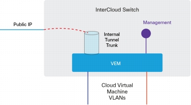
InterCloud Switch
The InterCloud Switch is a virtual machine deployed in a provider environment and is configured with an IP address that is assigned by the provider. The InterCloud Switch also has an embedded VEM that provides secure switching for virtual machines in the public cloud. The following interfaces are associated with an InterCloud Switch (Figure 6):
• Management interface
– The management interface is an internal interface that is configured with an enterprise address.
– This interface is used as the source interface for Layer 3 control communication with the InterCloud VSM.
• Internal tunnel trunk interface
– This interface is used to trunk the VLANs from the embedded VEM in the InterCloud Switch to the VEM on the InterCloud Extender through the site-to-site tunnel. Packets sent on the internal tunnel trunk interface are encrypted and sent over the provider public interface, and packets sent on the provider public interface are encrypted and sent over internal tunnel trunk interface.
– By default, this interface is assigned the port profile N1K_Cloud_Default_Trunk, which is preconfigured on the InterCloud VSM.
– The port profile can be changed by selecting a different port profile in Cisco Prime NSC during creation of the InterCloud Link. Different port profiles generally are needed if the same VSM supports multiple InterCloud Links that extend different sets of VLANs.
• Cloud virtual machine interfaces
– These interfaces are the secure tunnel endpoints on the InterCloud Switch to virtual machines in the public cloud.
– The virtual machine interfaces connected to these interfaces are configured with port profiles on the InterCloud VSM (and also appear as virtual Ethernet [vEth] interfaces).
• Provider public interface
– Cisco Prime NSC uses this interface to configure the InterCloud Switch.
– This interface is used as the endpoint for the secure tunnel with the InterCloud Extender.
– This interface is the only interface accessible over the public Internet.
– This interface is used as the tunnel endpoint for the secure tunnel to virtual machines in the public cloud.
Figure 6. InterCloud Switch Interfaces
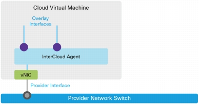
Cloud Virtual Machines
The cloud virtual machines are modified versions of the enterprise virtual machines that include an InterCloud Agent. The InterCloud Agent provides support for multiple NICs and for secure tunneling between the cloud virtual machine and the InterCloud Switch. The interfaces for the cloud virtual machine (Figure 7) are as follows:
• Cloud virtual machine provider public interface
– Cisco Prime NSC uses this interface to configure the cloud virtual machine.
– The access to the provider interface is restricted to prevent an unauthorized user from logging in directly.
• Cloud virtual machine overlay interfaces
– These interfaces are used to connect the virtual machines in the public cloud to the InterCloud Switch through secure tunnels.
– These interfaces are configured with port profiles on the InterCloud VSM.
– A maximum of eight virtual NICs (vNICs) are supported for a cloud virtual machine.
– These interfaces can be configured through Cisco Prime NSC to change the port profile, IP address configuration, and DNS information.
Figure 7. Cloud Virtual Machine Interfaces
Cisco Nexus 1000V InterCloud Security
All data in motion is cryptographically isolated and encrypted within the Cisco Nexus 1000V InterCloud solution. This includes traffic exchanged between the InterCloud Extender and InterCloud Switch as well as traffic between the InterCloud Switch and cloud virtual machines. A Datagram Transport Layer Security (DTLS) tunnel is created between these endpoints to securely transmit this data. DTLS is a User Datagram Protocol (UDP)-based secure transmission protocol. The InterCloud Extender always initiates the creation of a DTLS tunnel.
If a firewall is protecting access to the internal network, UDP port 6644 must be opened in the outbound direction to send DTLS traffic from the InterCloud Extender to the InterCloud Switch. If ACLs are used instead of a firewall, both outbound access with source port 6644 and inbound access with destination port 6644 must be permitted.
The keys used for the tunnel between the InterCloud Extender and the InterCloud Switch and the tunnel between the InterCloud Switch and the cloud virtual machines are generated and maintained by Cisco Prime NSC. The encryption algorithm used is configurable, and different encryption strengths can be used for each tunnel depending on the level of security desired.
The supported encryption algorithms are:
• AES-128-GCM
• AES-128-CBC
• AES-256-GCM (Suite B)
• AES-256-CBC
• None
The supported hashing algorithms are:
• SHA-1
• SHA-256
• SHA-384
A default tunnel profile is pre-created in Cisco Prime NSC with AES-128-CBC as the encryption algorithm and SHA-1 as the hash function. You can create a new tunnel profile to use a different encryption algorithm or hash function. Modification of the default tunnel profile is not recommended.
You can also set a rekey period through Cisco Prime NSC to refresh the encryption keys.
Cisco Nexus 1000V InterCloud High Availability
High availability in Cisco Nexus 1000V InterCloud is implemented for each component of the Cisco Nexus 1000V InterCloud infrastructure.
High Availability for Cisco Prime Network Services Controller
Cisco Prime NSC is deployed as a virtual machine with VMware vCenter and uses the high-availability mechanism provided in VMware vCenter.
The InterCloud Link, which consists of the InterCloud Extender and the InterCloud Switch and the tunnel between them, is considered to be a single unit for the purposes of high availability. When an InterCloud Link is created in high-availability mode, two pairs of InterCloud Extender and InterCloud Switch virtual machines are created. These virtual machines are configured with their own individual IP addresses and must be able to communicate with Cisco Prime NSC.
Upon instantiation of the virtual machines, Cisco Prime NSC pushes the high-availability role to both deployed InterCloud Extender virtual machines. The active InterCloud Extender and InterCloud Switch establish a secure tunnel between them, and the active InterCloud Switch establishes the secure tunnel with the cloud virtual machines. The standby InterCloud Extender and InterCloud Switch also establish a secure tunnel between them.
When a failure is detected in the active InterCloud Switch or InterCloud Extender, the entire high-availability entity, consisting of the endpoints and the secure tunnels, is brought down. The standby InterCloud Extender and InterCloud Switch become active and replace the failed pair. In addition, the newly active InterCloud Switch establishes secure access tunnels with the cloud virtual machines. The failed InterCloud Extender and InterCloud Switch are rebooted to help ensure that they come up in a standby role.
The following prerequisites must be met to begin deploying Cisco Nexus 1000V InterCloud:
• The first release supports VMware vSphere Version 5.0 or 5.1 as the enterprise virtual machine manager. The Cisco Enterprise Plus license is not required for Cisco Nexus 1000V InterCloud.
• The cloud provider supported is Amazon Web Services. An AWS account must be set up, and the access credentials must be available.
• The Internet router and firewall must allow outbound and inbound traffic originating from the enterprise network to the range of AWS IP addresses for the following protocols and ports:
– Port TCP 80: HTTP access from Cisco Prime NSC to call provider APIs and communicate with Cisco Nexus 1000V InterCloud virtual machines in the provider cloud
– Port TCP 443: HTTPS access from Cisco Prime NSC for AWS calls and communication with Cisco Nexus 1000V InterCloud virtual machines in the provider cloud
– Port TCP 22: SSH from Cisco Prime NSC to Cisco Nexus 1000V InterCloud virtual machines in the provider cloud
– Port UDP 6644: DTLS data tunnel
– Port TCP 6644: DTLS control tunnel
If the ports required for communication are not opened, you can run the command test intercloud
ics-reachability on the InterCloud Extender CLI to verify reachability.
• After you install Cisco Prime NSC, you must configure Network Time Protocol (NTP) to help ensure that the time is synchronized with that of AWS.
Cisco Nexus 1000V InterCloud Common Deployment Scenarios
Cisco Nexus 1000V InterCloud requires access from the enterprise to the public Internet to access the public provider cloud. This access need leads to some specific considerations in planning to deploy Cisco Nexus 1000V InterCloud in an enterprise. Fundamentally, the security requirements for the enterprise management network determine the following two choices:
• Whether to use the management interface or the tunnel interface on the InterCloud Extender as the source for the DTLS tunnel to the InterCloud Switch in the provider
• The VLAN that will be extended to the provider cloud for InterCloud Switch management; the VSM in the enterprise must be able to reach the InterCloud Switch management interface
Table 1 lists the communication requirements and IP addresses needed to deploy Cisco Nexus 1000V InterCloud. Depending on the deployment scenario, some IP addresses may not be required.
Table 1. Communication Requirements and IP Addresses for Deploying Cisco Nexus 1000V InterCloud
Component
Interface
Connectivity Requirements
Cisco Prime Network Services Controller
Management
• VMware vCenter Server
• InterCloud Extender management
• InterCloud Switch management
• Cloud virtual machines provider public IP address
InterCloud VSM
Management
• InterCloud Extender management
• InterCloud Switch management
InterCloud Extender
Management
• InterCloud VSM management
• InterCloud Switch provider public IP address (if tunnel source)
• Cisco Prime NSC management
Tunnel
• InterCloud Switch provider public IP address (if tunnel source)
InterCloud Switch
Management
• InterCloud VSM management
• InterCloud Extender management and tunnel (tunnel source)
• Cisco Prime NSC management
Provider public IP address (assigned by provider)
• Cisco Prime NSC management
• Cloud virtual machine provider public IP address
Cloud Virtual Machine
Provider public IP address (assigned by provider)
• Cisco Prime NSC management
• InterCloud Switch provider public IP address
Overlay interfaces
• Cloud virtual machines overlay interfaces
• Enterprise virtual machines
Tunnel Interface as Tunnel Endpoint and Enterprise Management Network Extended to Cloud
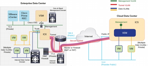
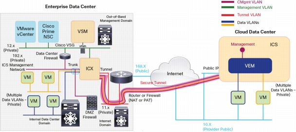
Figure 8 shows a typical enterprise data center design with three typical domains. The management domain is used only for out-of-band management and has no connection to the public Internet. The data domain is for the workloads within the data center, and the Internet domain has a private network going through a router and firewall providing NAT and PAT to access the public Internet. These domains are typically isolated from each other using a combination of Cisco Virtual Security Gateways (VSGs) and firewalls, providing a DMZ (safe) area for external-facing components.
In this scenario, the typical deployment of the Cisco Nexus 1000V InterCloud components is as follows:
• VMware vCenter, Cisco Prime NSC, InterCloud VSM, InterCloud Extender, and InterCloud Switch are on the same management VLAN.
• The management network is extended to the provider cloud for InterCloud Switch management.
• The tunnel interface is used as the tunnel source and will be in a DMZ with external access.
• Cisco Prime NSC requires external access and will pass through a DMZ firewall to be connected to the public domain.
Figure 8. Tunnel Interface as Tunnel Endpoint and InterCloud Switch on Enterprise Management Network
Tunnel Interface as Tunnel Endpoint and Separate Management Network for InterCloud Switch
For deployments in which the security rules or regulations do not allow extension of the private management network in the enterprise to the public domain, InterCloud Switch management can be placed on a separate VLAN that is extended from the enterprise.
Figure 9 shows a typical deployment in this scenario. The only differences between this deployment example and the one is Figure 8 are that a VLAN separate from the management VLAN must be allocated to extend to the cloud, and a mechanism must be provided to route between this VLAN and the management VLAN for the InterCloud Switch to communicate with the VSM.
Figure 9. Tunnel Interface as Tunnel Endpoint and InterCloud Switch on Separate Management Network
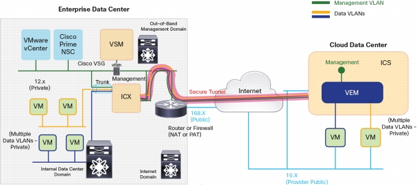
Management Interface as Tunnel Endpoint and Enterprise Management Network Extended to Cloud
The management interface on the InterCloud Extender can also be used as the tunnel source. This scenario is less likely scenario in customer environments, but it is supported. This scenario may be likely in a lab environment.
Figure 10 shows a typical deployment with the management interface used as the tunnel endpoint. In this case, the tunnel interface and VLAN are no longer required and do not need to be configured.
Figure 10. Management Interface as Tunnel Endpoint and InterCloud Switch on Enterprise Management Network
Cisco Nexus 1000V InterCloud Use Cases
Use Case 1: Migrate Workloads to the Public Cloud
After a network extension has been created by means of an InterCloud Link, virtual machines in the enterprise VMware vCenter can be migrated to the public cloud through the Enterprise tab on Cisco Prime NSC (Figure 11). The migration is a cold migration; the virtual machine is shut down at the start of the procedure, migrated, and then started in the cloud. The virtual machine in the enterprise will remain powered off.
Figure 11. Migrating a Virtual Machine Through Cisco Prime NSC
For a user, the process of migrating a workload requires just a few clicks. The most important configuration performed is the assignment of a port profile on the InterCloud VSM for the virtual machine to use after it has been migrated. Behind the scenes, Cisco Prime NSC reads the VMDK file for the virtual machine, converts it to AMI format, adds the InterCloud Agent, and copies the final image to the provider using provider API calls. The virtual machine is then brought up on the provider side and can be viewed through the Public Cloud tab in the Cisco Prime NSC web user interface.
All virtual machines in the public cloud can have only locally attached storage. If a virtual machine in the enterprise is migrated, all its associated storage is also migrated to AWS. This detail is an important consideration because the disk size will directly affect the amount time needed for virtual machine migration.
Use Case 2: Create Virtual Machines from Templates
Users who do not have a completely virtualized infrastructure or who are working in a multiple-hypervisor environment can upload an image to Cisco Prime NSC and create a template of that image in the public cloud. The template in the cloud can then be used to create virtual machines. Virtual machine attributes, such as the disk and memory, and network properties, such as the VLAN and IP address, can be modified during the creation of the virtual machine. In this way, users can easily and rapidly provision new workloads when necessary.
Use Case 3: Apply Features for Virtual Machine Traffic
Version 5.2(1)IC1(1.1) of Cisco Nexus 1000V InterCloud includes support for ACL and multicast traffic for virtual machines running in the public cloud. These features are configured on the port profiles in the InterCloud VSM and applied on the InterCloud Switch.
Version 5.2(1)IC1(1.2) includes support for Netflow and ACL logging.
Use Case 4: Secure Zoning with Cisco Virtual Security Gateway (Experimental)
Cisco Virtual Security Gateway is a zone-based firewall that provides protection for east-west traffic in a data center. Traditionally VSG is deployed in the enterprise data center and managed through Cisco Prime NSC. Cisco VSG is enabled by Cisco's vPath technology that provides intelligent traffic steering and policy offload.
Version 5.2(1)IC1(1.2) of Cisco Nexus 1000V InterCloud adds support for securing cloud workloads using Cisco Virtual Security Gateway deployed in the enterprise data center. The traffic flowing through cloud VMs is redirected through Cisco vPath in the cloud to a VSG instance in the enterprise. The VSG support is intended for Proof of Concept deployments and includes support for network attributes to define VSG rules. The version of Cisco VSG required is 4.2(1)VSG2(1.1).
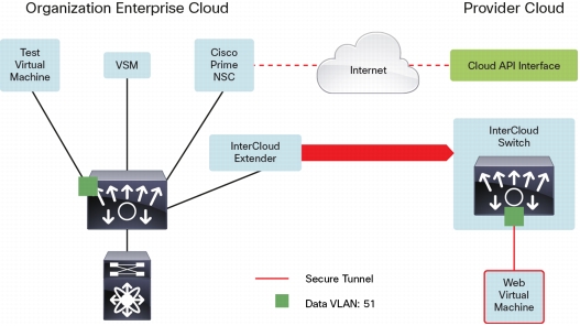
Deployment Example: Two-Tier Web Application
In this use case, the ABC organization is trying to migrate a development and test workload to AWS. The web server that needs to be tested will be moved to AWS, and the client machine accessing it will continue to reside in the enterprise data center. The client and web server virtual machines are both on VLAN 55 in the enterprise, and after the web server is migrated it should continue to be on VLAN 55 and accessible at the same IP address as before.
Figure 12 shows the deployment scenario considered here. In this simple lab deployment scenario, the management interface is used as the tunnel endpoint, and the management VLAN is extended to the public cloud.
Figure 12. Migrating the Web Tier in a Two-Tier Web Development Virtual Application
Note: This document does not discuss the installation and basic setup of Cisco Prime NSC or the Cisco Nexus 1000V InterCloud VSM. For this information, please refer to the following installation guides:
This example assumes the enterprise is running the Cisco Nexus 1000V as the virtual switch. VMware vSwitch and DVS are also supported, but they are not discussed in this document.
Step 1: Configure the port profiles on the enterprise Cisco Nexus 1000V for the InterCloud Extender.
The InterCloud Extender has three interfaces: management, tunnel, and trunk. This example uses the management interface as the tunnel source. Cisco Prime NSC configures the management and tunnel interfaces on the InterCloud Extender virtual machine with the same port profile, but the tunnel interface is not used. The management VLAN is 252, and the data VLANs being extended are 51 through 60. Verify that this VLAN configuration is present on the VSM and upstream switches.
port-profile type vethernet ICX-Trunk
vmware port-group
switchport mode trunk
switchport trunk allowed vlan 51-60,252
no shutdown
description ICX Trunk port-profile
state enabled
port-profile type vethernet Access-252
vmware port-group
switchport mode access
switchport access vlan 252
no shutdown
description ICX Management port-profile
state enabled
Step 2: Configure the port profiles on the InterCloud VSM.
The InterCloud Switch and the virtual machines running in the cloud are configured with port profiles from the Cisco Nexus 1000V. These are configured as access port profiles. In addition, the InterCloud VSM is preconfigured with a N1K_Cloud_Default_Trunk port profile. This port profile needs to be configured to allow the VLANs being extended and with the system VLAN configuration for the InterCloud Switch management VLAN.
port-profile type vethernet N1K_Cloud_Default_Trunk
switchport mode trunk
switchport trunk allowed vlan 51-60,252
no shutdown
publish port-profile
max-ports 64
system vlan 252
state enabled
port-profile type vethernet ICS-Mgmt
switchport mode access
switchport access vlan 252
no shutdown
publish port-profile
system vlan 252
state enabled
port-profile type vethernet Cloud-VM-55
switchport mode access
switchport access vlan 55
no shutdown
publish port-profile
state enabled
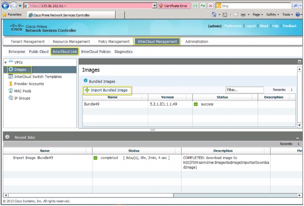
Step 3: Upload images to Cisco Prime NSC.
To deploy an InterCloud Link, the InterCloud Extender and InterCloud Switch images must be uploaded to Cisco Prime NSC. Multiple infrastructure images can be uploaded and are distinguished by a configurable version number. During deployment, the InterCloud Extender and InterCloud Switch image chosen must have the same version number.
The procedure below is used to upload a bundled image containing the infrastructure images and InterCloud Agent images to Cisco Prime NSC. The option to upload a bundled image instead of individual infrastructure and ICA images was introduced in version 5.2(1)IC1(1.2). For details on how to upload images with version 5.2(1)IC1(1.1) please refer to the installation guide for the release.
To upload a bundled image choose InterCloud Management > InterCloud Link > Images and click + Import Bundled Image (Figure 13).
Figure 13. Import Infrastructure Images
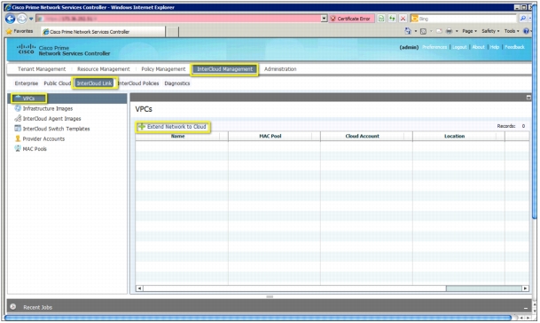
Step 4: Extend the network to the cloud.
To extend the network to the cloud, choose InterCloud Management > InterCloud Link > VPCs and click + Extend Network to Cloud (Figure 14).
Figure 14. Extend the Network to the Cloud
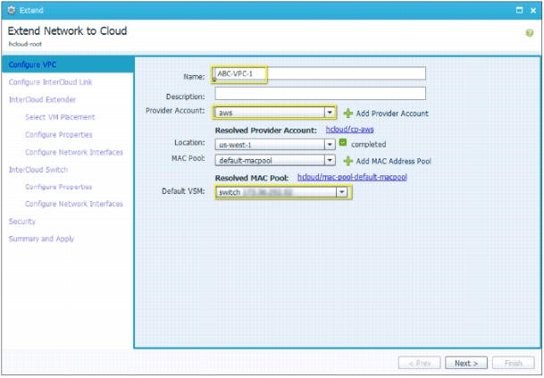
A dialog box will open, where you can enter the configuration details of the virtual private cloud (VPC) and InterCloud Link (Figure 15).
Figure 15. Configure VPC
To configure the VPC, do the following:
• In the Name field, enter a name for the VPC.
• In the Description field, optionally enter a description.
• Select an existing provider account from the drop-down menu or create a new provider account. This example assumes that a provider account has been created.
• Select the region for the VPC. By default, the default region for the provider is displayed.
• Select an existing MAC address pool from drop-down menu or create a new MAC address pool. The MAC address for virtual machines in the VPC will be assigned MAC addresses from this pool.
• Select a VSM instance to provide the distributed switch for the VPC.
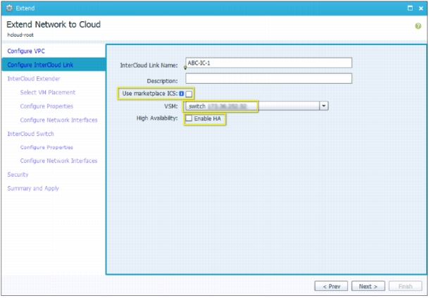
Click Next to add an InterCloud Link (Figure 16).
Figure 16. Configure InterCloud Link
On the Configure InterCloud Link screen, do the following:
• In the Name field, enter a name for the InterCloud Link.
• In the Description field, optionally enter a description.
• Uncheck the Use marketplace ICS box. In this example a local ICS is used.
• Select a VSM for the InterCloud Link.
• If high availability is desired, check the Enable HA box. In this example, high availability is selected.
Click Next.
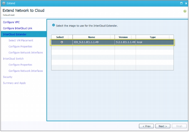
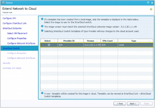
Select an image from the list of Infrastructure images available (Figure 17).
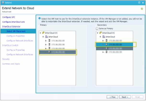
Select a host from the enterprise VMware vCenter inventory to deploy the primary and secondary InterCloud Extenders. The best approach is to select a different host for the secondary extender, but you can select the same host if you want (Figure 18).
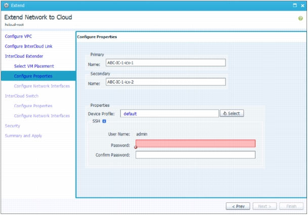
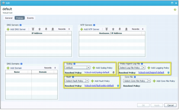
The device profile allows a user to configure properties such as Domain Name System (DNS), NTP, and syslog server information for the InterCloud Extender. In addition, the log file location can be modified. The example here uses the default device profile (Figure 20).
Figure 20. Default Device Profile
Click Next.
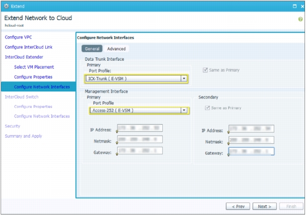
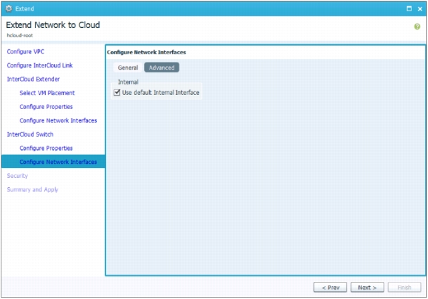
On the Configure Network Interfaces screen (Figure 21), do the following:
• Select a port profile for the data trunk interface. The drop-down list is populated with all the port groups and port profiles configured for the host selected to deploy the InterCloud Extender in VMware vCenter. The example here uses the ICN-Trunk port profile configured earlier on the enterprise VSM.
• Select a port profile for the management interface. The drop-down list is populated with all the port groups and port profiles configured for the host selected to deploy the InterCloud Extender in VMware vCenter. The example here uses the Access-252 port profile configured earlier.
• If the port profiles for the secondary extender are different from those for the primary extender, enter this information. In this example, the same port profiles are used for both.
• If the tunnel interface is being used as the tunnel source, click the Advanced tab to configure it. In this example, the management interface is used.
• Configure the IP address, net mask, and gateway for the primary and secondary InterCloud Extenders.
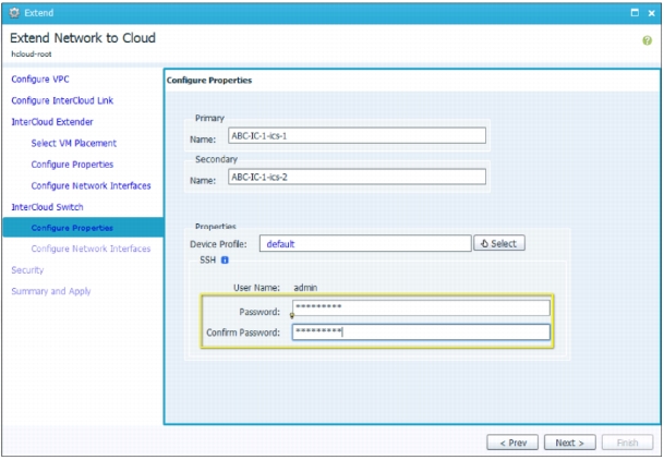
The device profile allows a user to configure properties such as DNS, NTP, and syslog server information for the InterCloud Switch. In addition, the log file location can be modified. This example uses the default device profile shown in Figure 20.
Click Next.
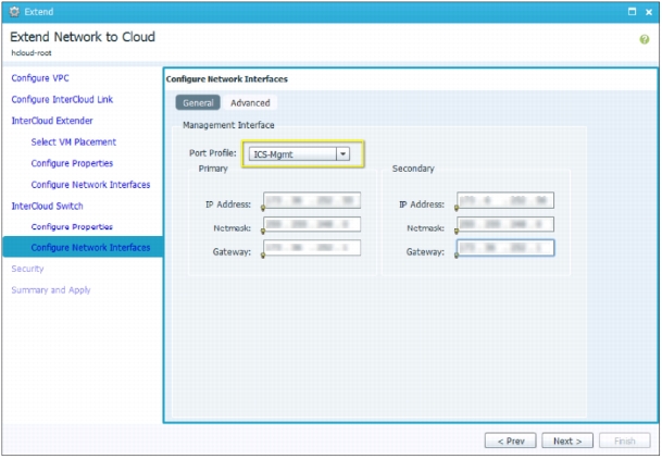
On the Configure Network Interfaces screen (Figure 24), do the following:
• Select a port profile for the management interface. The drop-down list is populated with all the port profiles configured in the InterCloud VSM. This example uses the ICS-Mgmt port profile configured earlier.
• Configure the IP address, net mask, and gateway for the primary and secondary InterCloud Switches.
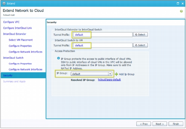
On the Configure Tunnel Profile screen (Figure 26), do the following:
• In the InterCloud Extender to InterCloud Switch Tunnel Profile field, select the default tunnel profile or select a different preconfigured tunnel profile. This tunnel profile determines the encryption methodology and critical parameters for the connection between the InterCloud Extender and the InterCloud Switch.
a. In the InterCloud Switch to VM Tunnel Profile field, select the default tunnel profile or select a different preconfigured tunnel profile. This tunnel profile determines the encryption methodology and critical parameters for the connection between the InterCloud Switch and the virtual machine in the public cloud.
• Version 5.2(1)IC1(1.2) adds support for configuring and IP group for an InterCloud Link. An IP Group identifies a set of IP addresses that are allowed to access the public IP address of the InterCloud Switch VM and cloud Virtual Machines. Configure an IP Group to prevent unauthorized access to VMs running in the cloud.
The default tunnel profile uses AES-128-CBC as the encryption algorithm and SHA-1 as the hash function. The default IP Group is 0.0.0.0/0, which allows all access to cloud VMs and InterCloud Switch.
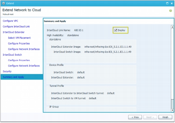
Click Finish to deploy the InterCloud Link (Figure 27).
Figure 27. InterCloud Switch: Summary and Apply
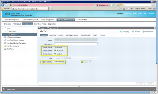
Step 5: Verify the InterCloud Link.
Choose InterCloud Management > InterCloud Link > VPCs > VPC name > IC Name. After the deployment is complete, the InterCloud Link will be shown as "deployed" with the configuration state shown as "applied." The tunnel status should be shown as "operational" and the high-availability status should be shown as "activestandby" (Figure 28).
Figure 28. Verify the InterCloud Link
The InterCloud Extender and InterCloud Switch images will be registered with the InterCloud VSM as service modules. You can verify this registration on the VSM using this CLI command:
If the tunnel status is not listed as Up, the ports required for communication may not be opened. Use the command test intercloud ics-reachability. If all ports are reachable, the output is as follows:
ABC-IC-1-icx-1# intercloud test ics-reachability
PORT STATE SERVICE REASON
6644/tcp open ctrl-channel success
6644/udp open data-tunnel success
22/tcp open ssh success
80/tcp open http success
443/tcp open https success
Migrating the Web Server to the Cloud
The web server and client virtual machine are configured with IP addresses in the 192.168.1.x subnet on VLAN 55 in the enterprise data center. The web server IP address is 192.168.1.5, and the client IP address is 192.168.1.1. The web server virtual machine is migrated to AWS and retains the same VLAN and IP address configuration.
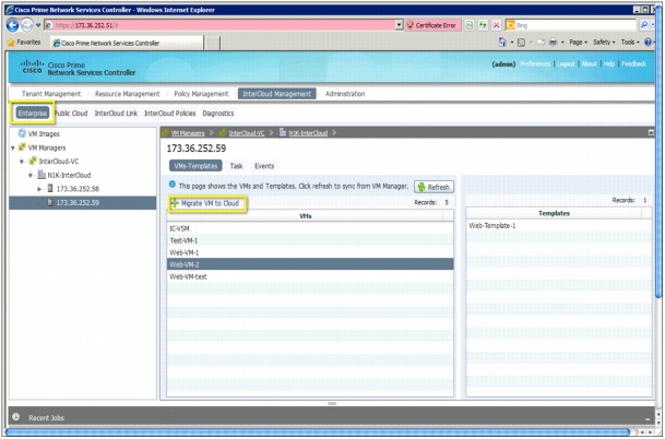
Step 1: Migrate the virtual machine.
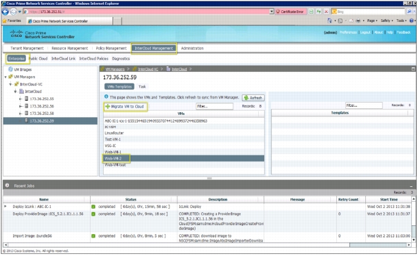
Choose InterCloud Management > Enterprise > VM Managers > VCenter > Datacenter > Cluster > Host. Select the virtual machine Web-VM-2. After the virtual machine is selected, + Migrate VM to Cloud will appear. Click this option to start the migration (Figure 29).
Figure 29. Select the Virtual Machine to Migrate
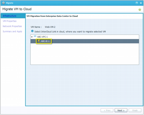
A dialog box for virtual machine migration will open (Figure 30).
Figure 30. Migrate Virtual Machine: Select the VPC and InterCloud Link
Select the VPC and InterCloud Link to which the virtual machine will be migrated. Click Next.
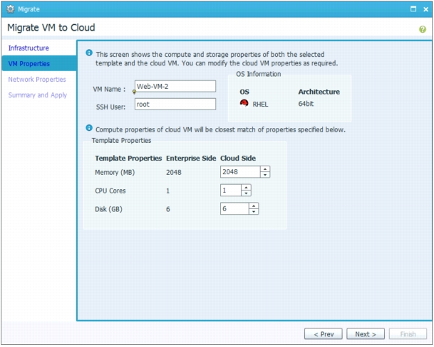
Change the virtual machine properties if desired (Figure 31).
Note: The amount of time needed for migration depends on the size of the disk being migrated and the latency of the link between the provider and enterprise cloud.
Click Next.
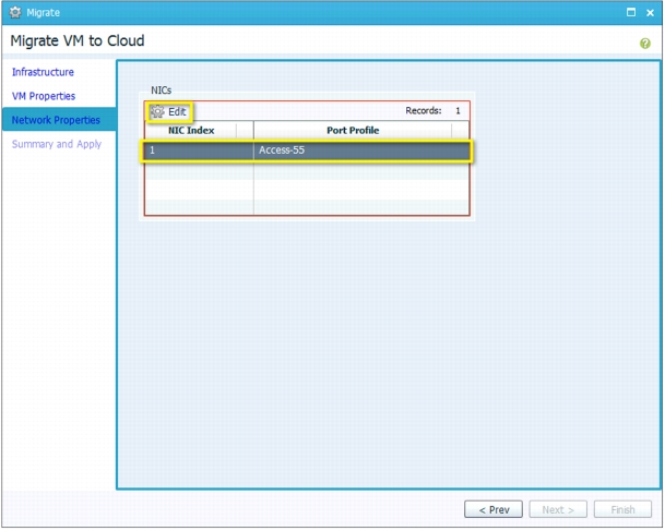
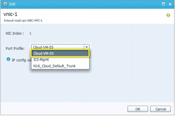
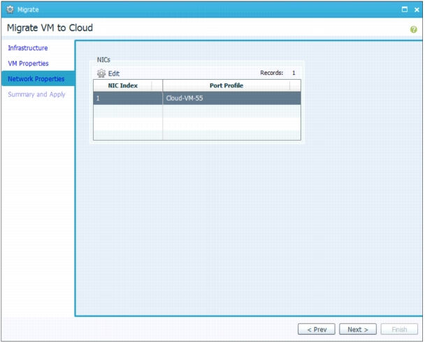
In the Network Properties pane, select the NIC and click Edit to edit the networking properties (Figure 32).
Select the port profile from the drop-down list. In this example, the web server needs to be on VLAN 55, and the port profile used is Cloud-VM-55. The IP address configuration will be derived from the virtual machine configuration.
Click OK to accept the network properties (Figure 34).
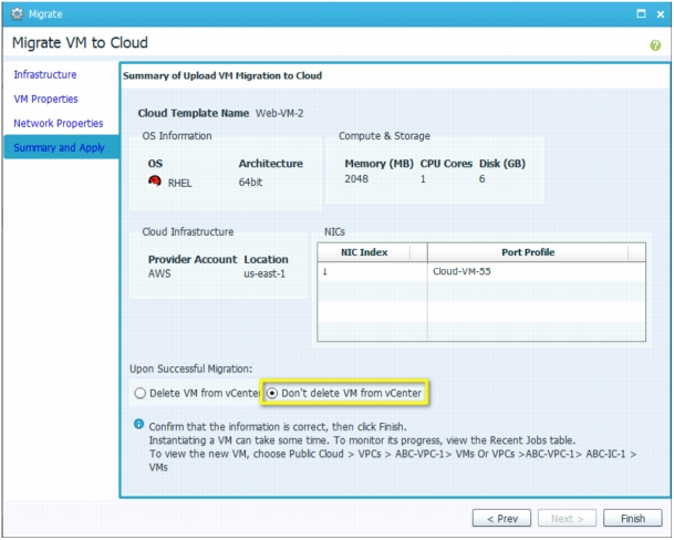
Figure 35. Migrate Virtual Machine: Summary and Apply
In this example, the virtual machine will not be deleted from VMware vCenter. Click Finish to start the migration.
Verifying Traffic Between the Client Virtual Machine and Web Server in the Cloud
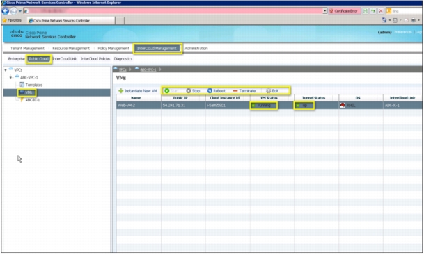
After the virtual machine has been migrated, you can view it by choosing InterCloud Management > Public Cloud > VMs.
Step 1: Verify that the virtual machine is present in the public cloud.
The migrated virtual machine will be running in the public cloud. It can be stopped, rebooted, terminated, and configured from Cisco Prime NSC (Figure 36).
Figure 36. View Virtual Machine in Public Cloud
Step 2: Verify that the virtual machine is assigned to a vEth interface on the VSM.
The following CLI command shows the vEth interface assigned to the web server in the cloud:
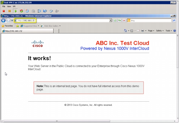
From the console of the client virtual machine, try to access the webpage using the address 192.168.1.5. If the web server migrated successfully, the webpage should be displayed (Figure 38).
Figure 37. Web Server Connectivity
Conclusion
Cisco Nexus 1000V InterCloud is used to securely extend an enterprise data center to a provider public cloud. By implementing Cisco Nexus 1000V InterCloud, an organization can run enterprise applications and services in a public shared provider environment without having to redesign applications, services, or security policies. A secure Layer 2 extension connects the virtual machines in the cloud to the enterprise virtual machines, and Cisco Prime NSC provides a single point of management for setting up the extension and managing applications that are migrated to the public cloud.
This document presented the features and capabilities of Cisco Nexus 1000V InterCloud. It discussion some options for configuring the enterprise network to prepare for Cisco Nexus 1000V InterCloud deployment and some best practices for extending the enterprise network. This document also demonstrated how to deploy Cisco Nexus 1000V InterCloud to address a simple development and test deployment use case involving a 2-tier web application.
Glossary
• Cisco Prime Network Services Controller: Cisco Prime NSC is used to configure and manage Cisco Nexus 1000V InterCloud. Cisco Prime NSC interfaces with the virtual machine manager on the enterprise and provider APIs to provide single-pane management for all virtual machines that are part of the Cisco Nexus 1000V InterCloud solution.
• Virtual private cloud: A VPC is a logical container for InterCloud Links that represents a secure and isolated private cloud within the provider environment. A VPC is restricted to a single region in AWS.
• InterCloud Link: The InterCloud Link consists of an InterCloud Extender and an InterCloud Switch and the secure extension between them. In the Cisco Nexus 1000V InterCloud solution, a VPC can have up to four InterCloud Links configured. Each InterCloud Link is configured with its own encryption keys.
• InterCloud Extender: The InterCloud Extender is a virtual machine that is part of the base Cisco Nexus 1000V InterCloud infrastructure. It is instantiated automatically by Cisco Prime NSC in the enterprise VMware vCenter when an InterCloud Link is created. It provides extension capabilities and is the secure tunnel endpoint on the enterprise side.
• InterCloud Switch: The InterCloud Switch is a virtual machine that is part of the base Cisco Nexus 1000V InterCloud infrastructure. It is instantiated automatically by Cisco Prime NSC in the provider cloud when an InterCloud Link is created. It provides secure switching for virtual machines in the cloud and is the secure tunnel endpoint on the provider side.
• InterCloud Agent: The InterCloud Agent provides secure encryption capabilities and multiple-NIC support for virtual machines running in the provider cloud. Cisco Prime NSC inserts it automatically before instantiating a virtual machine in the cloud.
• Cisco Nexus 1000V Series Virtual Supervisor Module: The Cisco Nexus 1000V Series VSM controls multiple VEMs as one logical modular switch. Instead of physical line-card modules, the VSM supports multiple VEMs running in software with the physical servers.
• Cisco Nexus 1000V Series Virtual Ethernet Module: The Cisco Nexus 1000V Series VEM runs as part of the VMware ESX or ESXi kernel and replaces the VMware virtual switch feature.
For More Information
For more information about the Cisco Nexus 1000V Series, please refer to the following URLs: