The Cisco Nexus® B22 Blade Fabric Extender for HP (Cisco Nexus B22HP) provides an extension of the Cisco Nexus switch fabric to the HP server edge. Logically, it behaves like a remote line card to a parent Cisco Nexus 5000 Series Switch. The fabric extender and the parent Cisco Nexus 5000 Series Switch together form a distributed modular system. The Cisco Nexus B22HP forwards all traffic to the parent Cisco Nexus 5000 Series Switch over eight 10 Gigabit Ethernet uplinks. Low-cost uplink connections of up to 10 meters can be made with copper Twinax cable, and longer connections of up to 100 meters can use the Cisco Fabric Extender Transceiver (FET-10G). Standard 10-Gbps optics such as short reach (SR) and long reach (LR) are also supported. Downlinks to each server are auto negotiating for 1 and 10 Gigabit Ethernet and work with all HP Ethernet and converged network adapter (CNA) mezzanines, allowing customers a choice of Ethernet, Fibre Channel over Ethernet (FCoE), or Small Computer System Interface over IP (iSCSI) connections. Because the Cisco Nexus B22 is a transparent extension of a Cisco Nexus 5000 Series Switch, traffic can be switched according to policies established by the Cisco Nexus 5000 Series Switch with a single point of management.
The Cisco Nexus B22 provides the following benefits:
• Highly scalable, consistent server access: This distributed modular system creates a scalable server access environment with no reliance on Spanning Tree Protocol and with consistency between blade and rack servers.
• Simplified operations: The availability of one single point of management and policy enforcement using upstream Cisco Nexus 5000 Series Switches eases the commissioning and decommissioning of blades through zero-touch installation and automatic configuration of fabric extenders.
• Increased business benefits: Consolidation, reduced cabling, investment protection through feature inheritance from the parent switch, and the capability to add functions without the need for a major equipment upgrade of server-attached infrastructure all contribute to reduced operating expenses (OpEx) and capital expenditures (CapEx).
Each member of the Cisco Nexus B22 integrates into the I/O module slot of a third-party blade chassis, drawing both power and cooling from the blade chassis itself.
Network Diagram
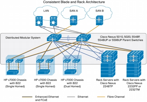
Figure 1 presents a sample network topology that can be built using the Cisco Nexus B22HP, Cisco Nexus 2000 Series Fabric Extenders, and Cisco Nexus 5000 Series Switches. In this topology, the Cisco Nexus 5000 Series serves as the parent switch, performing all packet switching and policy enforcement for the entire distributed modular system. The Cisco Nexus 5000 Series also serves as the only point of management for both configuration and monitoring within the domain, making it simple to manage blade server and rack server connections together.
Figure 1. Cisco Nexus Virtual Chassis Topology
The Cisco Nexus 5000 Series Switches, along with the Cisco Nexus 2000 Series and Cisco Nexus B22, create a distributed modular system that unifies the data center architecture. Within this distributed modular system, both blade servers and rack servers are managed identically. This approach allows the use of the same business and technical processes and procedures for the network when addressing the computing environment.
The left most blade chassis in Figure 1 contains dual Cisco Nexus B22HP fabric extenders. Each Cisco Nexus B22HP is singly attached to a parent Cisco Nexus 5500 switch platform, a connection mode referred to as straight through mode. The fabric links can either be statically pinned or put into a PortChannel. This connection mode helps ensure that all data packets from a particular Cisco Nexus B22 enter the same parent Cisco Nexus 5500 switch platform. This approach may be necessary when certain types of traffic must be restricted to either the left or right Cisco Nexus 5500 switch platform: for instance, to maintain SAN A and SAN B separation. Also, in this example the connections to individual blade servers are in active-standby mode, which helps ensure traffic flow consistency but does not fully utilize the server network interface card (NIC) bandwidth.
The second blade chassis from the left in Figure 1 improves on the first with the creation of an Ethernet virtual PortChannel (vPC) from the blade servers to the Cisco Nexus 5500. This vPC places the Ethernet portion of the NICs in an active-active configuration, giving increased bandwidth to each host. The FCoE portion of the CNA is also configured as active-active but maintains SAN A and SAN B separation because each virtual Fibre Channel (VFC) interface is bound to a particular link at the server. This configuration also achieves high availability through redundancy, and it can withstand a failure of a Cisco Nexus 5500 switch platform, a Cisco Nexus B22HP, or any connecting cable. This topology is widely used in FCoE deployments.
The third blade chassis from the left in Figure 1 contains Cisco Nexus B22HP fabric extenders that connect to both Cisco Nexus 5500 switch platforms through vPC for redundancy. In this configuration, active-active load balancing using vPC from the blade server to the Cisco Nexus 5500 switch platform cannot be enabled. However, the servers can still be dual-homed with active-standby or active-active transmit-load-balancing (TLB) teaming. This topology is only for Ethernet traffic because SAN A and SAN B separation between the fabric extender and the parent switch is necessary.
The last two setups illustrate how rack mount servers can connect to the same Cisco Nexus parent switch using rack-mount Cisco Nexus 2000 Series Fabric Extenders. The topology for blade servers and rack-mount servers can be identical if desired.
Hardware Installation
Installation of the Cisco Nexus B22HP in the rear of the HP BladeSystem c7000 chassis is similar to the installation of other I/O modules (IOMs). The layout of the HP BladeSystem c7000 chassis, server types, and mezzanine cards used determine the slots that should be populated with the Cisco Nexus B22HP for 1 and 10 Gigabit Ethernet connectivity. Table 1 summarizes the typical options for half-height servers using dual-port 10 Gigabit Ethernet devices.
Table 1. Mapping of HP BladeSystem c7000 Half-Height Server Mezzanine Card to IOM Bay
Card
IOM
LAN on motherboard (LOM)
IOM bays 1 and 2
Mezzanine card 1
IOM bays 3 and 4
Mezzanine card 2
IOM bay 5 and 6
After the Cisco Nexus B22HP fabric extenders are installed, the onboard administrator (OA) should be updated to at least Version 3.5 to help ensure that all functions and graphics are present. No configuration is required from the chassis onboard administrator.
Fabric Extender Management Model
The Cisco Nexus fabric extenders are managed by a parent switch through the fabric interfaces using a zero-touch configuration model. The switch discovers the fabric extender by a using detection protocol.
After discovery, if the fabric extender has been correctly associated with the parent switch, the following operations are performed:
1. The switch checks the software image compatibility and upgrades the fabric extender if necessary.
2. The switch and fabric extender establish in-band IP connectivity with each other. The switch assigns an IP address in the range of loopback addresses (127.15.1.0/24) to the fabric extender to avoid conflicts with IP addresses that might be in use on the network.
3. The switch pushes the configuration data to the fabric extender. The fabric extender does not store any configuration locally.
4. The fabric extender updates the switch with its operational status. All fabric extender information is displayed using the switch commands for monitoring and troubleshooting.
This management model allows fabric extender modules to be added without adding management points or complexity. Software image and configuration management is also automatically handled without user intervention.
Fabric Connectivity Options
The Cisco Nexus B22HP creates a distributed modular chassis with the Cisco Nexus parent switch after a fabric connection has been made over standard 10-Gbps cabling. This connection can be accomplished using any of the following types of interconnects:
• Cisco passive direct-attach cables (1M, 3M, or 5M)
• Cisco active direct-attach cables (7M or 10M)
• Cisco standard Enhanced Small Form-Factor Pluggable (SFP+) optics (SR or LR)
• Cisco Fabric Extender Transceivers
After the fabric links have been physically established, the logical configuration of the links needs to be performed. There are two methods of connection for the fabric links to the Cisco Nexus B22HP:
• Static pinning fabric interface connection
• PortChannel fabric interface connection
Static Pinning Fabric Interface Connection
Static Pinning is the default method of connection between the fabric extender and the Cisco Nexus parent switch. In this mode of operation, a deterministic relationship exists between the host interfaces and the upstream parent with up to eight fabric interfaces. These fabric interfaces are equally divided among the 16 server-side host ports. If fewer fabric ports are allocated, then more server ports are assigned to a single fabric link. The advantage of this configuration is that the traffic path and the amount of allocated bandwidth are always known for a particular set of servers.
Since static pinning will group host-side ports into individual fabric links, you should understand its relationship and how ports are grouped. The size of the port groups is determined by the number of host ports divided by the max-link parameter value. Thus, if the max-link parameter is set to 2, then eight host ports would be assigned to each link. The interfaces will be grouped in ascending order starting from the interface 1. Thus, interfaces 1 to 8 will be pinned to one fabric link, and interfaces 9 to 16 will be pinned to a different interface (Table 2).
Table 2. Interface Assignment with Two Fabric Links
Interface
Fabric Link
1, 2, 3, 4, 5, 6, 7, and 8
Fabric link 1
9, 10, 11, 12, 13, 14, 15, and 16
Fabric link 2
Table 3 summarizes the assignment with four fabric links with the max-link parameter set to 4, the interfaces are divided into four groups.
Table 3. Interface Assignment with Two Fabric Links
Interface
Fabric Link
1, 2, 3, and 4
Fabric link 1
5, 6, 7, and 8
Fabric link 2
9, 10, 11, and 12
Fabric link 3
13,14,15, and 16
Fabric link 4
Table 4 summarizes the assignment of eight fabric links with the max-link parameter set to 8; the interfaces are divided into eight groups.
Table 4. Interface Assignment with Two Fabric Links
Interface
Fabric Link
1 and 2
Fabric link 1
3 and 4
Fabric link 2
5 and 6
Fabric link 3
7 and 8
Fabric link 4
9 and 10
Fabric link 5
11 and 12
Fabric link 6
13 and 14
Fabric link 7
15 and 16
Fabric link 8
Note: The assignment of the host-side ports is always based on the configured max-link parameter and not the actual physical number of fabric ports connected. Be sure to match the max-link parameter with the actual number of physical links used.
Note: The relationship of host-side ports to parent switch fabric ports is static. If a fabric interface fails, all its associated host interfaces are brought down and will remain down until the fabric interface is restored.
PortChannel Fabric Interface Connection
The PortChannel fabric interface provides an alternative method of connection between the parent switch and the Cisco Nexus B22HP fabric extender. In this mode of operation, the physical fabric links are bundled into a single logical channel. This approach prevents a single fabric interconnect link loss from disrupting traffic to any one server. The total bandwidth of the logical channel is shared by all the servers, and traffic is spread across the members through the use of a hash algorithm.
• For a Layer 2 frame, the switch uses the source and destination MAC addresses.
• For a Layer 3 frame, the switch uses the source and destination MAC addresses and the source and destination IP addresses.
Since both redundancy and increased bandwidth are possible, configuration of the fabric links on a PortChannel is the most popular connection option.
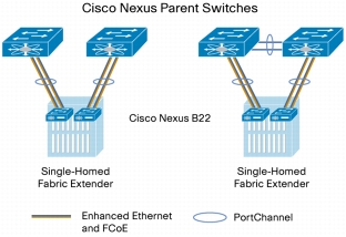
Figure 2 shows PortChannel designs.
Note: A fabric interface that fails in the PortChannel does not trigger a change to the host interfaces. Traffic is automatically redistributed across the remaining links in the PortChannel fabric interface.
Figure 2. PortChannel Designs
Configuring a Fabric PortChannel
1. Log into the first parent switch and enter into configuration mode.
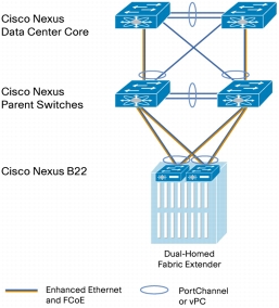
vPCs allow links that are physically connected to two different Cisco Nexus switches to form a PortChannel to a downstream device. The downstream device can be a switch, a server, or any other networking device that supports IEEE 802.3ad PortChannels. vPC technology enables networks to be designed with multiple links for redundancy while also allowing those links to connect to different endpoints for added resiliency (Figure 3).
Now the two switches have been configured to support vPC links to other devices. These connections can be used for upstream links to the data center core. These vPC links can be used for connections to hosts in the data center, allowing additional bandwidth and redundant links.
Server Network Teaming
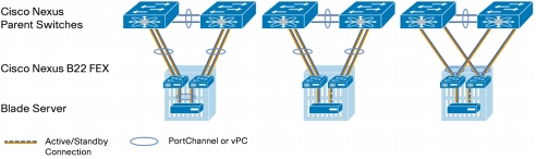
Server NIC teaming provides an additional layer of redundancy to servers. It allows multiple links to be available, for redundancy. In the blade server environment, server network teaming was typically limited to active-standby configurations and could not provide active-active links, because active-active links required EtherChannel or Link Aggregation Control Protocol (LACP) connection to a single switch. Since the Cisco Nexus B22HP fabric extender is an extension of the parent switch, EtherChannel or LACP connections can be created between the blade server and the virtual chassis. Dual Cisco Nexus 5000 Series switches can be used with vPC for additional switch redundancy while providing active-active links to servers, thus enabling aggregate 40-Gbps bandwidth with dual links (Figure 4).
Figure 4. Fabric Link and Server Topologies
Creating Host-Side vPC for Server Links with LACP
1. Enable LACP on both parent switches.
5548-Bottom (config)# feature lacp
2. Create the blade server vPC and add the member interface.
nexus-5548-Bottom# configure terminal
Enter configuration commands, one per line. End with CNTL/Z.
5548-Bottom(config-if)# channel-group 201 mode active
nexus-5558-Top# configure terminal
Enter configuration commands, one per line. End with CNTL/Z.
5548-Top(config)# interface port-channel 201
5548-Top(config-if)# vpc 201
5548-Top(config-if)# switchport mode access
5548-Top(config-if)# no shutdown
5548-Top(config-if)# interface ethernet 104/1/1
5548-Top(config-if)# channel-group 201 mode active
Configuring the HP Blade Server (Microsoft Windows 2008 Release 2)
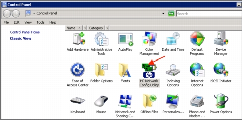
1. Open the Control Panel and open HP Network Config Utility.
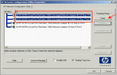
2. Select the network ports and click Team.
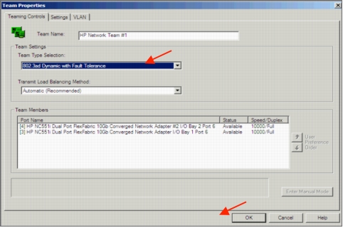
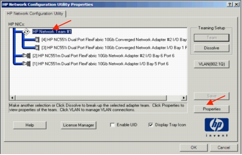
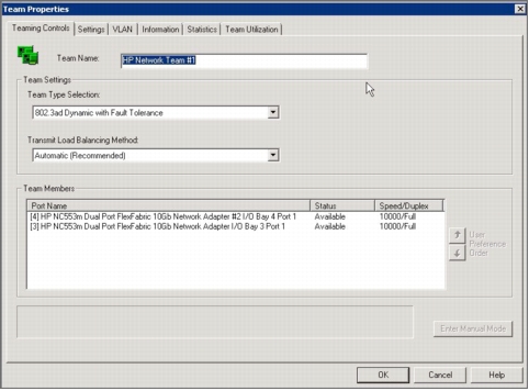
3. After the team is formed, click Properties.
4. From the Team Type Selection drop-down menu, choose 802.3ad Dynamic with Fault Tolerance to match the Cisco Nexus vPC configuration with LACP. Then click OK.
5. Click OK to complete the NIC teaming configuration. It may take a few minutes to complete after you click OK.
To verify that the vPC is formed, go to one of the Cisco Nexus 5000 Series Switches to check the status of the server PortChannel interface. Since the pair of Cisco Nexus 5000 Series Switches is in a vPC configuration, they each have a single port in the PortChannel. Checking the status of the PortChannel on each parent switch shows that channel group 201 is in the "P - Up in port-channel" state on each switch. A check from the HP Network Configuration Utility will show the status "Available" for each link that is up in the PortChannel.
FCoE combines LAN and storage traffic on a single link, eliminating dedicated adapters, cables, and devices for each type of network, resulting in savings that can extend the life of the data center. The Cisco Nexus B22HP is the building block that enables FCoE traffic to travel outside the HP BladeSystem chassis.
1. Enable the FCoE personality on the HP NC551 or NC553 CNA.
2. Install the FCoE driver in the server OS.
3. Configure quality of service (QoS) to support FCoE on the Cisco Nexus 5000 Series.
4. Enable the FCoE feature on the Cisco Nexus 5000 Series.
5. Create the SAN A and SAN B VLANs.
6. Create VFC interfaces.
The steps are described in detail on the following pages.
1. Enable FCoE on the CNA.
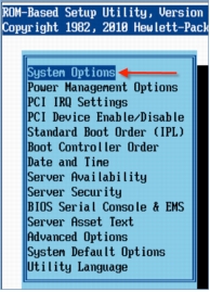
By default, the HP NC551 and NC553 CNAs have their personality set to iSCSI. The personality needs to be changed to FCoE to support FCoE traffic. You make this change in the BIOS of the system and the BIOS of the mezzanine cards.
Choose System Options.
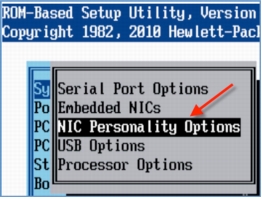
Choose NIC Personality Options.
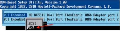
From the NIC Personality Options menu, choose FCoE.
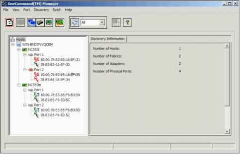
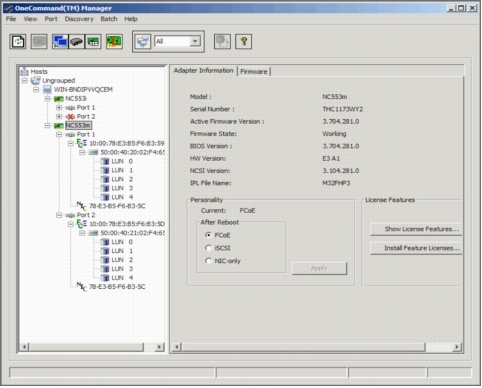
Save the changes by exiting the BIOS; then reboot the server to enable the changes. FCoE capabilities are enabled at this time. Verify that the latest FCoE drivers and firmware are loaded for the respective operating system. The latest versions can be obtained from the HP Support website. The FCoE drivers are separate from the Ethernet NIC drivers. Figure 5 shows the ports configured for FCoE and the drivers loaded.
Figure 5. OneCommand FCoE Utility Showing Ports Configured for FCoE with Drivers Loaded
Configuring the Cisco Nexus 5000 Series and B22HP for FCoE
This example assumes that a server in bay 2 is using IOM 3 and 4 for FCoE connectivity.
1. Enable the FCoE feature on the Cisco Nexus 5000 Series Switch.
N5548-Bottom # config terminal
Enter configuration commands, one per line. End with CNTL/Z.
switch(config)# feature fcoe
FC license checked out successfully
fc_plugin extracted successfully
FC plugin loaded successfully
FCoE manager enabled successfully
FC enabled on all modules successfully
Warning: Ensure class-fcoe is included in qos policy-maps of all types
N5548-Bottom (config)#
N5548-Top # config terminal
Enter configuration commands, one per line. End with CNTL/Z.
switch(config)# feature fcoe
FC license checked out successfully
fc_plugin extracted successfully
FC plugin loaded successfully
FCoE manager enabled successfully
FC enabled on all modules successfully
Warning: Ensure class-fcoe is included in qos policy-maps of all types
N5548-Top (config)#
2. Configure QoS to support FCoE.
N5548-Bottom(config)# system qos
N5548-Bottom(config-sys-qos)# service-policy type qos input fcoe-default-in-policy
N5548-Bottom(config-sys-qos)# service-policy type queuing input fcoe-default-in-policy
N5548-Bottom(config-sys-qos)# service-policy type queuing output fcoe-default-out-policy
N5548-Bottom(config-sys-qos)# service-policy type network-qos fcoe-default-nq-policy
N5548-Bottom(config-sys-qos)#
N5548-Top(config)# system qos
N5548-Top(config-sys-qos)# service-policy type qos input fcoe-default-in-policy
N5548-Top(config-sys-qos)# service-policy type queuing input fcoe-default-in-policy
N5548-Top(config-sys-qos)# service-policy type queuing output fcoe-default-out-policy
N5548-Top(config-sys-qos)# service-policy type network-qos fcoe-default-nq-policy
N5548-Top(config-sys-qos)#
3. Create the virtual Fibre Channel interface (physical port).
Displays the details of the fabric extender module, including the IOM bay number, rack name, and enclosure information of the HP BladeSystem c-Class chassis
The advent of Cisco Nexus 2000 Series Fabric Extenders has enabled customers to benefits from both top-of-rack (ToR) and end-of-row (EoR) designs while reducing the costs associated with cabling and cooling in EoR models without introducing any additional management points, unlike with traditional ToR designs. This unique architecture has been tremendously successful in the first generation of fabric extenders and rack-mount servers. The Cisco Nexus B22 Blade Fabric Extender for HP brings these innovations to the HP BladeSystem c-Class chassis. The Cisco Nexus B22HP supports both 1 and 10 Gigabit Ethernet connectivity, allowing a smooth migration from 1 Gigabit Ethernet to 10 Gigabit Ethernet for blade servers. Unified fabric with FCoE deployment outside the HP BladeSystem chassis is finally achieved. This solution solidly brings Cisco networking innovations to the server access layer from rack-mount servers using Cisco Nexus 2000 Series Fabric Extenders in third-party blade chassis.