Downloads |
Innovative Network System Virtualization Technology Redefines Multilayer Network Architecture
What You Will Learn
Challenge
Business Benefits
• VSS simplifies network complexity and management overhead by 50 percent, thus increasing operational efficiency and lowering operating expenses (OpEx).
• VSS provides deterministic sub-200-ms stateful convergence, resulting in no disruption to application or business.
• VSS maximizes the available bandwidth in the already installed network infrastructure, increasing return on investment (ROI) and reducing additional capital expenditures (CapEx) to add capacity.
Solution: Virtual Switching System 1440 Technology Overview
Figure 1. Virtual Switching System 1440
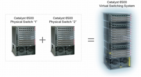
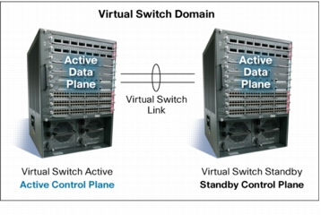
Figure 2. Virtual Switching System 1440 Redundancy State
• VSS 1440 is managed using a single point of management through the active virtual switch member. The number of devices that need to be managed by Simple Network Management Protocol [SNMP] is reduced by 50 percent.
• VSS 1440 has a single combined configuration file for both virtual switch members, and VSS allows configuration of both the switches from a single management interface (using a CLI or SNMP).
• Policy changes or configuration file changes has additional overhead in the traditional model with two separate points of management. The network operator has to manually synchronize both the devices, and it is prone to errors. In VSS 1440, any update is synchronized between the two physical switches.
• Gateway redundancy protocols such as Virtual Router Redundancy Protocol/Hot Standby Router Protocol (VRRP/HSRP) are required to help ensure a smooth first hop gateway address for the hosts. These protocols have the following weaknesses:
– Three separate IP address per subnet (one for active router, one for standby router, and one for virtual IP address)
– Overhead of configuring the protocol parameters
– Convergence time of these protocols varies depending on the number of instances of these protocols configured in a system
VSS has a single gateway IP address and offers full first hop redundancy. With VSS, configuration is not only greatly simplified; it also eliminates the need for these gateway redundancy protocols and the associated overhead of these protocols.
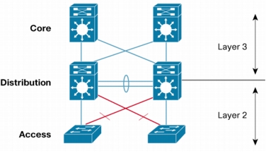
• Multichassis EtherChannel® (Figure 4) creates simplified loop-free topologies, eliminating the dependency on Spanning Tree Protocol.
Figure 3. VSS 1440 Loop-Free Physical Topology Compared to Traditional Network
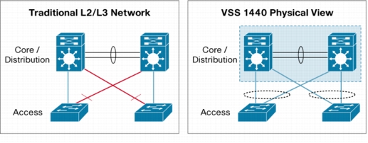
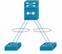
Figure 4. VSS 1440 Loop-Free Logical View with Multichassis EtherChannel
• In a VSS, a virtual switch member failure results in an interchassis stateful failover with no disruption to applications that rely on network state information. VSS eliminates Layer 2/Layer 3 protocol reconvergence if a virtual switch member fails, resulting in deterministic, sub-200-ms stateful virtual switch recovery. Unlike VSS, the traditional network design does not offer deterministic convergence times as the convergence depends on the following parameters:
– Gateway protocol convergence (HSRP/VRRP state changes)
– Routing protocol reconvergence (Open Shortest Path First/Enhanced Interior Gateway Routing Protocol [OSPF/EIGRP] routing process)
– Spanning Tree Protocol topology convergence (root changes to the standby switch)
– Number of VLANs or subnets, because multiple protocol convergence is unpredictable and in the range of few seconds
• VSS utilizes EtherChannel (802.3ad or PAgP or Manual ON mode) for deterministic, sub-second Layer 2 link recovery, unlike convergence based on Spanning Tree Protocol in a traditional network design. Spanning Tree Protocol requires the blocking port to go forwarding if the active link fails, and depending on the number of VLANs, the blocked link time to forward may be varied. With VSS, all links are forwarding at all times, and loss of one of the uplinks just represents a loss of link in EtherChannel. Traffic going through the still active link continues to get forwarded with no disruption, while the traffic that was sent on the now failed link is sent over the remaining active link(s). (Cisco allows up to 8 links in an EtherChannel bundle.)
• VSS activates all available Layer 2 bandwidth across redundant Cisco Catalyst 6500 Series Switches. VSS also maximizes the link utilization on these connections with even and granular load balancing based on Cisco EtherChannel or standards-based 802.3ad protocol. In traditional networks, Spanning Tree Protocol blocks ports to prevent loops. The blocked ports are not utilized. An advanced design with Spanning Tree Protocol involves VLAN-based load balancing, which still does not evenly load balance the links in a typical campus network.
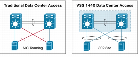
• VSS allows standards-based link aggregation (802.3ad) for server network interface card (NIC) teaming across redundant data center switches, maximizing server bandwidth throughput. Traditional NIC vendor-based teaming has the following deficiencies:
– NIC vendor proprietary feature
– Usually only active/standby model: standby link not utilized
– Send-on-many and receive-on-one NIC teaming does not allow bidirectional utilization of links (Figure 5) and cannot be configured across redundant data center switches (two physical switches)
Figure 5. VSS 1440 Allows Bidirectional Bandwidth Usage with 802.3ad
• VSS eliminates unicast flooding issues typically seen in the traditional Layer 2/Layer 3 network because of VLAN load-balancing schemes using First Hop Redundancy Protocol (FHRP)/Spanning Tree Protocol, resulting in asymmetrical routing. VSS 1440 synchronizes the state of Address Resolution Protocol (ARP) and MAC address tables between the two chassis, thus eliminating unicast flooding caused by asymmetrical routing.
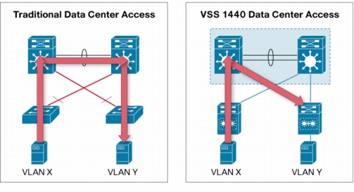
• VSS reduces latency and bandwidth usage by optimally routing intracampus or intra-data center traffic with least number of hops (Figure 6). VSS selects the direct link to destination as all links are forwarding. In the traditional Layer 2/Layer 3 topology, inter-VLAN routing can result in extra hop and wasted bandwidth caused by Spanning Tree Protocol blocked ports.
Figure 6. VSS 1440 Reduces Distribution Layer Switching Latency by 50 Percent
Transitioning to VSS 1440 from a Traditional Multilayer Network
Figure 7. Traditional Multilayer Network
• Hardware requirements: The Virtual Switching Supervisor 10GE (VS-S720-10G-3C or VS-S720-10G-3CXL) is needed on both the virtual switch members. While in VSS mode, initial software release supports all existing Cisco Catalyst 6700 Series Switch Ethernet modules and Network Analysis Module (NAM) 1 and 2 service modules in a Cisco Catalyst 6500-E and 6500 Series chassis. Future software releases will add support to additional service modules.
• Software requirements: VSS is supported in Cisco IOS® Software or Cisco IOS Software with modularity starting with Release 12.2(33)SXH1. VSS supports all software features in the initial release except for Multiprotocol Label Switching (MPLS)/IPv6 features. Future software releases will add support for MPLS and IPv6 features.
• Network device requirement: Any network device can connect to VSS 1440. To maintain high availability of the attached devices, we recommend that the device be dual attached to both VSS members. Singly attached devices are supported. Multichassis EtherChannel is supported in either IEEE 802.3ad (Link Aggregation Control Protocol [LACP]), Cisco PAgP, or manual ON mode.
• Converting to VSS mode considerations: If it is a new install, covert the standalone switches to VSS and perform the needed configuration. If you are converting from an existing production network to VSS, plan a maintenance window to convert the existing two standalone switches to a combined VSS switch. The network configuration becomes much simpler when you covert to VSS mode from the traditional network; however, those configuration changes are not automatically performed and are the responsibility of the administrator. Remember to configure Multichassis EtherChannel on any relevant attached devices. Configuring Multichassis EtherChannel is exactly same as configuring traditional EtherChannel.
• High-availability considerations: To maintain high availability of the attached devices, we recommend that the device be dual attached to both VSS members. Singly attached devices are supported but will lose connectivity when the switch to which they are attached fails. In the initial release of software, only a single supervisor per chassis is supported. Dual supervisor per VSS member is planned for future software release.
• Image upgrade considerations: VSS supports both Cisco IOS Software and Cisco IOS Software with modularity. Patching in Cisco IOS Software modularity can be performed in service, assuming all devices are dual-homed and connectivity is maintained. Full-image Cisco IOS Software upgrade, however, requires you to allocate for up to 1 minute downtime for the VSS. This restriction will be removed in a future software release.
Figure 8. VSS 1440 Deployed in the Distribution Layer
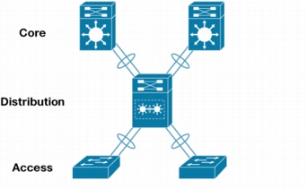
Figure 9. VSS 1440 Deployed in the Core and Distribution Layer
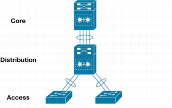
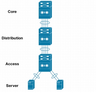
Figure 10. VSS Deployed in the Core, Distribution, and Server Access in a Data Center Network
Why Cisco?
For More Information