Stateful Failover for the Cisco IOS® Firewall allows a router to continue processing and forwarding firewall session packets after a planned or unplanned outage occurs. A backup (secondary) router automatically takes over the tasks of the active (primary) router if the active router loses connectivity for any reason. This process is transparent and requires neither adjustment nor reconfiguration of any remote peer.
Cisco IOS Classic Firewall
Cisco IOS Classic Firewall creates temporary openings in access lists at firewall interfaces. These openings are created when specified traffic exits your internal network through the firewall. The openings allow returning traffic (that would normally be blocked) and additional data channels to enter your internal network back through the firewall. The traffic is allowed back through the firewall only if it is part of the same session as the original traffic that triggered Cisco IOS Classic Firewall when exiting through the firewall.
Stateful Failover for the Cisco IOS Firewall
Stateful Failover for the Cisco IOS Firewall is designed to work in conjunction with Stateful Switchover (SSO) and Hot Standby Router Protocol (HSRP).
HSRP provides network redundancy for IP networks, helping ensure that user traffic immediately and transparently recovers from failures in network edge devices or access circuits. That is, HSRP monitors both the inside and outside interfaces so that if either interface goes down, the whole router is deemed to be down and ownership of firewall sessions is passed to the standby router (which transitions to the HSRP active state).
SSO allows the active and standby routers to share firewall session state information so that each router has enough information to become the active router at any time. To configure Stateful Failover for the Cisco IOS Firewall, a network administrator should enable HSRP, assign a virtual IP (VIP) address, and enable the SSO protocol.
Note: High Availability Stateful Failover supports only Cisco IOS Classic Firewall and does not support Cisco IOS Zone-Based Firewall.
Enabling HSRP: IP Redundancy and a Virtual IP Address
HSRP provides two services-IP redundancy and a VIP address. Each HSRP group can provide either or both of these services. Cisco IOS Firewall Stateful Failover uses the IP redundancy services from only one HSRP standby group. It can use the VIP address from one or more HSRP groups. Use the following guidelines to configure HSRP on the outside and inside interfaces of the router.
• Both the inside (private) and outside (public) interfaces must belong to separate HSRP groups, but the HSRP group number can be the same.
• The state of the inside and outside interfaces must be the same -- both interfaces must be in the active state or standby state; otherwise, the packets will not have a route out of the private network.
• Standby priorities should be equal on both active and standby routers. If the priorities are not equal, the higher-priority router will unnecessarily take over as the active router, negatively affecting uptime.
• The interface access control list (ACL) should allow HSRP traffic to flow through.
Each time an active device relinquishes control to become the standby device, the active device reloads. This function helps ensure that the state of the new standby device synchronizes correctly with the new active device.
SSO: Interacting Between the Cisco IOS Firewall Session
SSO is a method of providing redundancy and synchronization for many Cisco IOS Software applications and features. It is necessary for the Cisco IOS Firewall to learn about the redundancy state of the network and to synchronize its internal application state with its redundant peers.
Prerequisites: The HSRP should be configured before enabling SSO.
Prerequisites and Restrictions for Stateful Failover
• This document assumes that you have a complete Cisco IOS Firewall configuration on both active and standby routers.
• The Cisco IOS Firewall configuration that is set up on the active device must be duplicated on the standby device, including firewall protocols inspected, the interface ACLs, the global firewall settings, and the interface firewall configuration.
• Both the active and standby devices must run the identical version of the Cisco IOS Software, and both the active and standby devices must be connected through a hub or switch.
• HSRP requires the inside interface to be connected through LANs.
Device Requirements
• The active and standby Cisco IOS Software routers must be running the same Cisco IOS Software release: Release 12.4(6) T or later.
• Stateful Failover for the Cisco IOS Firewall requires that your network contains two identical routers that are available to be either the primary or secondary device. Both routers should be the same type of device, and they should have the same CPU and memory.
Supported Deployment Scenarios: Stateful Failover for the Cisco IOS Firewall
It is recommended that you implement Stateful Failover in one of the following deployment scenarios:
• Dual-LAN interface
• LAN-WAN interface
Dual-LAN Interface
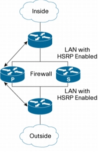
In a dual-LAN-interface scenario, the active and standby routers running the firewall are connected to each other through a LAN interface on both the inside and outside (Figure 1).
HSRP is configured on both the inside and outside interfaces. The next-hop routers in this scenario talk to the High Availability pair through the virtual IP address. In this scenario there are two virtual IP addresses, one on the inside and the other on the outside.
Virtual IP addresses cannot be advertised using routing protocols. You need to create static routes on the next hops to get to the virtual IP address.
Figure 1. Dual-Interface Network Topology
LAN-WAN Interface
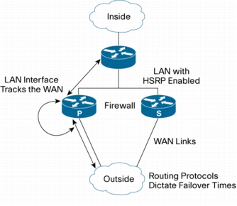
In a LAN-WAN scenario, the inside interface of the active standby pair running the firewall is connected through a LAN interface on the inside and a WAN interface on the outside (Figure 2). HSRP is configured on the inside interface. The inside network communicates with the High Availability pair using the inside virtual IP address.
You should configure HSRP tracking on the inside LAN interfaces to track the state of the outside WAN interface. If the outside WAN interface goes down on the active router, the LAN interface that is tracking it reduces the HSRP priority and initiates a failover to the standby router. Traffic from the outside flowing into the HSRP pair should now be directed to the new active device.
In the scenario where the LAN interfaces track the WAN interfaces, the failover to the standby router happens immediately. However, for traffic to start flowing on the new active router, routing convergence needs to happen. The net failover time is dictated by the routing protocol.
Figure 2. LAN WAN Network Topology
How to Configure Stateful Failover for Cisco IOS Firewalls
Configuration tasks for Stateful Failover include:
• Enabling HSRP: IP Redundancy and a Virtual IP Address
• Enabling SSO
• Enabling Stateful Failover for a Cisco IOS Firewall
• Configuring the Cisco IOS Classic Firewall High Availability Update Interval
Enabling HSRP: IP Redundancy and a Virtual IP Address
Use the following commands to enable HSRP on both interfaces of each router (Table 1):
1. enable
2. configure terminal
3. interface type number
4. standby standby-group-number name standby-group-name
Assigns a user-defined group name to the HSRP redundancy group
Note: The standby-group-number argument should be the same for both routers that are on directly connected interfaces. However, the standby-group-name argument should be different between two (or more) groups on the same router.
The standby-group-number argument can be the same on the other pair of interfaces as well.
Step 5
standbystandby-group-numberipip-address
Example:
Router(config-if)# standby 1 ip 209.165.201.1
Assigns an IP address that is to be "shared" among the members of the HSRP group and owned by the primary IP address
Note: The virtual IP address must be configured identically on both routers (active and standby) that are on directly connected interfaces.
Step 6
standbystandby-group-numbertrackinterface-name
Example:
Router(config-if)# standby 1 track Ethernet1/0
Configures HSRP to monitor the second interface so that if either of the two interfaces goes down, HSRP causes failover to the standby device
Note: Although this command is not required, it is recommended for dual-interface configurations.
Step 7
standby [group-number] preempt
Example:
Router(config-if)# standby 1 preempt
Enables the active device to relinquish control because of an interface tracking event
(Optional) Configures the time between hello packets and the time before other routers declare the active hot standby or standby router to be down
• holdtime: Holdtime is the amount of time the routers take to detect types of failure. A larger hold time means that failure detection will take longer.
For the best stability, it is recommended that you set the hold time between 5 and 10 times the hello interval time; otherwise, a failover could falsely occur when no actual failure has happened.
Configures the delay period before the initialization of HSRP groups
Note: It is suggested that you enter 120 as the value for the reload-delay argument and leave the min-delay argument at the preconfigured default value.
Step 10
Repeat.
Repeats this task on both routers (active and standby) and on both interfaces of each router.
Examples
The following example shows how to configure HSRP on a router:
interface Ethernet0/0
ip address 209.165.201.1 255.255.255.224
standby 1 ip 209.165.201.3
standby 1 preempt
standby 1 name HA-out
standby 1 track Ethernet1/0
standby delay minimum 120 reload 120
After you have successfully configured HSRP on both the inside and outside interfaces, you should enable SSO as described in the following section.
Enabling SSO
Use the following commands to enable SSO, which is used to transfer Cisco IOS Firewall session state information between two routers (Table 2):
Defines the redundancy scheme that is to be used; currently, "standby" is the only supported scheme
• standby-group-name: Must match the standby name specified in the standby name interface configuration command. Also, the standby name should be the same on both routers.
Note: Only the active or standby state of the standby group is used for SSO. The VIP address of the standby group is neither required nor used by SSO.
Step 5
exit
Example:
Router(config-red-interdevice)# exit
Exits interdevice configuration mode
Step 6
ipc zone default
Example:
Router(config)# ipc zone default
Configures the interdevice communication protocol, Inter-Process Communication (IPC), and enters IPC zone configuration mode
Use this command to initiate the communication link between the active router and standby routers.
Step 7
association 1
Example:
Router(config-ipczone)# association 1
Configures an association between the two devices and enters IPC association configuration mode
Step 8
protocol sctp
Example:
Router(config-ipczone-assoc)# protocol sctp
Configures Stream Control Transmission Protocol (SCTP) as the transport protocol and enters SCTP protocol configuration mode
Step 9
local-portlocal-port-number
Example:
Router(config-ipc-protocol-sctp)# local-port 5000
Defines the local SCTP port number that is used to communicate with the redundant peer and puts you in IPC transport-SCTP local configuration mode
• local-port-number: There is not a default value. This argument must be configured for the local port to enable interdevice redundancy. Valid port values are 1 to 65535.
The local port number should be the same as the remote port number on the peer router.
Defines at least one local IP address that is used to communicate with the redundant peer
The local IP addresses must match the remote IP addresses on the peer router. There can be either one or two IP addresses, which must be in the global Virtual Route Forwarding (VRF) process. A virtual IP address cannot be used.
Defines the remote SCTP port number that is used to communicate with the redundant peer and puts you in IPC transport-SCTP remote configuration
Note:remote-port-number: There is not a default value. This argument must be configured for the remote port to enable interdevice redundancy. Valid port values are 1 to 65535.
The remote port number should be the same as the local port number on the peer router.