In the late 1980s, DSL technology was developed to provide higher-speed digital data transmission over local telephone lines. As Internet applications gained momentum and became increasingly popular, higher bandwidth was needed to support the demand for faster download and upload speeds. Throughout the years, DSL technologies have evolved, and service providers throughout the world have deployed millions of DSL lines for consumer and business-class services.
Today, service providers continue to roll out DSL services using their copper lines, but with enhanced capabilities. Asymmetric DSL (ADSL) carriers are moving toward ADSL2+ standards. G.SHDSL carriers are adding Ethernet Framing Mode (EFM) options to support Ethernet services over copper lines. An increasing number of service providers are also adding very-high-bit-rate DSL 2 (VDSL2) to their portfolios to offer services with higher demand for bandwidth.
The Cisco® Integrated Services Router (ISR) platform is a critical component of service provider broadband DSL business services. These routers are deployed as business customer premises equipment (CPE) for small business and enterprise branch-office customers, with critical security, quality-of-service (QoS), and IP service-level agreement (IP SLA) features required for business services. QoS features on ISR platforms are enabled by service providers to prioritize voice and video traffic, and to provide service guarantees. For broadband DSL technologies, QoS can be implemented at network Layer 2 and Layer 3.
This document provides guidelines to implement Layer 2 and Layer 2 QoS for DSL services in ATM and VDSL2 deployments in Packet Transport Mode (PTM). Additionally, it describes scenarios when traffic shaping and service contracts may be compromised when the DSL line trains up at a rate lower than the configured rate.
Cisco ISR DSL Technology Overview
DSL technology on the Cisco ISR platforms has evolved over the years as new DSL standards have become available. Table 1 summarizes DSL technology options for the Cisco ISR and Cisco Integrated Services Routers Generation 2 (ISR G2) products. Please also refer to the Cisco ISR G2 website for details about Cisco's offering of broadband DSL technologies for business-class services.
Table 1. DSL Technology on the Cisco ISR Platforms
DSL Technology
Cisco ISR G2
Cisco ISR
Cisco 1900, 2900, and 3900 Series
Cisco 800 Series
Cisco 1800, 2800, and 3800 Series
Cisco 800 and Fixed 1800 Series
Multimode DSL Products (Recommended for New Deployments)
Multimode VDSL2, ADSL2, and ADSL2+ Annex A
EHWIC-VA-DSL-A
CISCO887VA
-
-
Multimode VDSL2, ADSL2, and ADSL2+ Annex B
EHWIC-VA-DSL-B
CISCO886VA
-
-
Multimode VDSL2, ADSL2, and ADSL2+ Annex M
EHWIC-VA-DSL-M
CISCO887VA-M
-
-
VDSL2- and ADSL-Only Products (End of Sale Announced or Pending)
VDSL2 Only
HWIC-1VDSL
CISCO887V
-
-
ADSL2+ over basic telephone service Annex A
HWIC-1ADSL,
HWIC-1ADSL-B/ST
CISCO867
CISCO887
HWIC-1ADSL,
HWIC-1ADSL-B/ST
CISCO857
CISCO877
CISCO1801
ADSL2+ over basic telephone service Annex M
HWIC-1ADSL-M
CISCO887M
HWIC-1ADSL-M
CISCO877M
CISCO1801M
ADSL2+ over ISDN Annex B
HWIC-1ADSLI, HWIC-1ADSLI-B/ST
CISCO886
HWIC-1ADSLI, HWIC-1ADSLI-B/ST
CISCO876
CISCO1802
G.SHDSL Products
G.SHDSL EFM
HWIC-4SHDSL-E
CISCO888E
-
-
G.SHDSL ATM
HWIC-2SHDSL, HWIC-4SHDSL
CISCO888
HWIC-2SHDSL, HWIC-4SHDSL
CISCO878
CISCO1803
Implementation of Layer 2 QoS for DSL Services
QoS implementation for DSL services includes provisioning the DSL virtual circuits to effectively support the type of services and applications over the DSL connection, and tuning the hardware queues to reduce latency. Because of architectural design changes, there are some differences in the ATM features on the newer ISR G2 multimode VDSL2, ADSL2, and ADSL2+ enhanced high-speed WAN interface card (EHWIC) modules and platforms, compared to the ISR DSL routers and high-speed WAN interface card (HWIC) modules. Please also refer to the Cisco 880VA series Q&A for a comparison of the ATM features between the two generations of products.
Layer 2 QoS on ATM PVC
For DSL services with ATM, QoS is configured on the ATM permanent virtual circuit (PVC) and is the means to provision DSL services. Service providers provision the PVCs based on service contracts with their customers, which delineate parameters in service categories such as maximum upstream and downstream rate, traffic prioritization, and delay management in order to ensure reliability and always-on DSL service with minimum downtime. Table 2 lists the service categories offered for DSL in ATM.
Table 2. Applications for Different Service Categories
Service Category
Application Examples
Constant bit rate (CBR) (for data, using ATM Adaptation Layer 5 [AAL5]):
• Useful for delay-sensitive applications
• Provides bandwidth and delay guarantees
Audio library, videoconferencing, and video on demand
Variable Bit Rate real time (VBR-rt):
• Useful for burstier delay-sensitive applications
• Provides bandwidth and delay guarantees
Voice over ATM (VoATM), compressed voice over IP, and videoconferencing
Variable Bit Rate non-real-time (VBR-nrt):
• Useful for bursty traffic
• Provides bandwidth guarantee
Interactive, bursty applications such as airline reservations or banking transactions
Unspecified Bit Rate (UBR):
• Useful for real best effort where there are no guarantees
File transfer, email, library browsing, fax transmission, Telnet, and LAN and remote-office interconnections
Enhanced UBR (UBR+):
• Useful for best-effort traffic requiring minimum throughput guarantees
Same as UBR, but seeks possible minimum bandwidth guarantee
You should choose a service category based on network application demand; the parameters for the service categories should be in line with the service contract defined for the PVC. It is not necessary to restrict to a particular type of service category to carry out ATM traffic, or to establish the same service categories on both ends of the link. However, each service category uses certain traffic parameters that best define the transmission characteristic of a type of traffic and help optimize traffic flow and meet the requirement of the service contract.
Table 3 provides information about the various traffic parameters available for the different service categories.
Table 3. Traffic Parameters to Guarantee Cell Rate
Service Category
Traffic Parameter
Constant Bit Rate (CBR)
Peak Cell Rate (PCR)
VBR-nrt
Sustainable Cell Rate (SCR)
VBR-rt
SCR
UBR+
Minimum Cell Rate (MCR)
UBR
None
In addition, each service category has an associated default transmission priority. The ATM service category defines how the ATM network devices treat the cells of the virtual circuit with respect to bandwidth guarantees, cell delays, and cell loss. The best use of bandwidth and performance optimization is achieved when the service category that best represents the type of traffic and applications carried over the PVC is chosen.
Tuning Queues
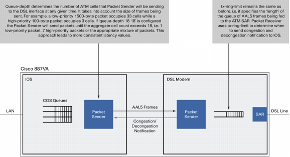
The tx-ring-limit and queue-depth commands provide a mechanism to tune the hardware queues to help reduce latency for delay-sensitive traffic, or to optimize data packet throughput. The queue-depth command for DSL interfaces was introduced with the new multimode VDSL2, ADSL2, and ADSL2+ EHWIC modules and platforms. It is applicable to DSL deployments using ATM only.
Because of architectural differences, the behavior of the tx-ring-limit command is different on the newer ISR G2 multimode VDSL2, ADSL2, and ADSL2+ EHWIC modules and platforms, compared to the behavior on the ISR DSL routers and HWIC modules.
Tuning tx-ring-limit on DSL HWICs and Cisco 850, 870, and 1800 Series DSL Platforms
To provide preferential treatment for delay-sensitive traffic such as voice, the hardware queue length has to be modified in such way that congestion is realized at the output queue on each PVC and hence the software queue (Layer 3 queue) stores the packet in the buffer to be treated by the congestion management mechanism such as Class-Based Weighted Fair Queuing/Low-Latency Queuing (CBWFQ/LLQ).
The command to modify the length of the hardware queue on the PVC is tx-ring-limit (refer to Table 4).
Table 4. tx-ring Command
Command
Purpose
tx-ring-limit <size >
Modifies the length of the hardware queue;
Size = 1 to 16; default is 16
The transmit ring (tx-ring) serves as a staging area for packets in line to be transmitted. The router needs to enqueue a sufficient number of packets on the transmit ring and guarantee that the interface driver has packets with which to fill available cell time slots.
The primary reason to tune the transmit ring is to reduce latency caused by queuing on the hardware queue. When tuning the transmit ring, consider the following:
• On any network interface, queuing forces a choice between latency and the amount of burst that the interface can sustain. Larger queue sizes sustain longer bursts while increasing delay. Tune the size of a queue when you feel the traffic of the virtual circuit is experiencing unnecessary delay.
• Consider the packet size. Configure a tx-ring-limit value that accommodates four packets. For example, if your packets are 1500 bytes, set a tx-ring-limit value of 16 = (4 packets) * (4 particles).
• Configure a low value with low-bandwidth virtual circuits, such as a 128-kbps SCR. For example, on a low-speed virtual circuit with an SCR of 160 kbps, a tx-ring-limit of 10 is relatively high and can lead to significant latency (for example, hundreds of milliseconds) in the driver-level queue. Tune the tx-ring-limit down to its minimum value in this configuration.
In other words, the size of the transmit ring needs to be small enough to avoid introducing latency due to queuing, and it needs to be large enough to avoid drops and a resulting effect on TCP-based flows.
An interface first removes the packets from the Layer 3 queuing system and then queues them on the transmit ring. Service policies apply only to packets in the Layer 3 queues and are transparent to the transmit ring.
Queuing on the transmit ring introduces a serialization delay that is directly proportional to the depth of the ring. An excessive serialization delay can affect latency budgets for delay-sensitive applications such as voice.
Cisco recommends reducing the size of the transmit ring for virtual circuits carrying voice to help ensure that the packets are queued in the Layer 3 queues and appropriate priority can be given to voice packets using LLQ.
Select a value based on the amount of serialization delay, expressed in seconds, introduced by the transmit ring. Use the following formula:
((P*8)*D)/S
where
P = Packet size in bytes; multiply by 8 to convert to bits
D = Transmit-ring depth
S = Speed of the virtual circuit in bps
Tuning tx-ring-limit and queue-depth Commands on the Multimode VDSL2, ADSL2, and ADSL2+ EHWIC Modules and Platforms
With the ISR G2 multimode VDSL2, ADSL2, and ADSL2+ EHWIC modules and platforms, the hardware queue length is also set by the tx-ring-limit command. The length of the hardware queue range is 2 to 128, with 128 being the default value.
In addition to the tx-ring-limit command, the queue-depth command is introduced on the Cisco ISR G2 platforms to better manage packet flow to and from the DSL interface. The commands can be used separately or together. Cisco recommends that you use both commands for deployments with low-latency requirements (Figure 1 and Table 5).
Figure 1. tx-ring-limit and queue-depth Commands
Table 5. Commands tx-ring-limit and queue-depth
Command
Purpose
tx-ring-limit <size >
Modifies the length of the hardware queue.
Size = 2 to 128; default is 128.
queue-depth <high, low >
Determines congestion and decongestion points on hardware queue.
High, low = 4 to 400; default is 40, when tx-ring-limit is configured (it represents the number packets sent from Cisco IOS® Software on a decongestion notification from the modem side).
Default is 128, when tx-ring-limit is not configured (it represents the high water mark on the modem side).
Both tx-ring-limit and queue-depth Are Configured
To best reduce latency for delay-sensitive traffic on the Cisco ISR G2 multimode VDSL2, ADSL2, and ADSL2+ EHWIC modules and platforms, Cisco recommends that you configure both tx-ring-limit and queue-depth.
The effect of the tx-ring-limit command on the DSL modem side follows (refer to Figure 1):
• High water mark: The congestion notification is generated when the number of packets sitting in modem tx-ring increases to this level
• Low water mark: The decongestion notification is generated when the number of packets sitting in modem tx-ring decreases to this level
• The input "size" value of the tx-ring-limit command is used as the high water mark on the modem side
• When size > 16, low water mark will be (size - 4)
• When size <= 16, low water mark will be (size - 2)
• When size = 2, low water mark will be 1
The effect of the queue-depth command on the Cisco IOS Software side AAL5 cell transmit threshold follows:
• Cisco IOS Software will send up to the "high" number of AAL5 cells to the modem side at one time.
• On decongestion notification from Cisco IOS Software, the software will send the maximum "high" number of AAL5 cells at one time to avoid sending too many data packets that will sit in the modem tx-ring and cause head-of-line latency for voice packets.
• Lower latency is achieved with a lower value of "high", but the risk of underrun is higher. Typically, "high" should be slightly bigger than the value of tx-ring-limit used. The traffic profile must also be considered when configuring this value. The recommended configuration guideline for queue-depth follows:
The Cisco ISR G2 multimode VDSL2, ADSL2, and ADSL2+ EHWIC modules and platforms cannot achieve optimal latency results when only the tx-ring-limit command is used. For customers who previously deployed ATM QoS on the Cisco ISR DSL HWICs (Cisco 850, 870, and 1800 Series DSL platforms), Cisco recommends that you revise the original configuration using tx-ring-limit only to achieve better latency results for delay-sensitive traffic on the newer Cisco ISR G2 platforms. Please refer to the previous discussion about the details of using both tx-ring-limit and queue-depth commands to accomplish this configuration. When configured alone, the tx-ring-limit command helps to optimize data traffic-only throughput.
The following behavior of the tx-ring-limit-only configuration is expected on the Cisco ISR G2 multimode VDSL2, ADSL2, and ADSL2+ EHWIC modules and platforms:
The effect on the DSL modem side follows (refer to Figure 1):
• High water mark: The congestion notification is generated when the number of packets sitting in the modem tx-ring increases to this level
• Low water mark: The decongestion notification is generated when the number of packets sitting in the modem tx-ring decreases to this level
• The input "size" value of the tx-ring-limit command is used as the high water mark on the modem side
• When size <= 16, low water mark will be (size - 2)
• When size > 16, low water mark will be (size - 4)
The effect on the Cisco IOS Software side AAL5 cell transmit threshold follows:
• Cisco IOS Software will send as many as packets as are available in the Cisco IOS Software transmit queue to the modem side
• On decongestion notification from Cisco IOS Software, the software will send the default maximum 40 AAL5 cells at a time
Only queue-depth Is Configured
The queue-depth command is supported on Cisco ISR G2 multimode VDSL2, ADSL2, and ADSL2+ EHWIC modules and platforms deployed using ATM only. This configuration using queue-depth only is recommended when your goal is optimizing data-only traffic throughput. It works similarly to the tx-ring-limit-only configuration described in the previous section.
The following is expected behavior when only the queue-depth command is configured:
The effect on the DSL modem side follows (refer to Figure 1):
• High water mark: The congestion notification is generated when the number of packets sitting in the modem tx-ring increases to this level
• Low water mark: The decongestion notification is generated when the number of packets sitting in the modem tx-ring decreases to this level
• The input "high" value of the queue-depth command is used as the high water mark on the modem side
• The input "low" value of the queue-depth command is used as the low water mark on the modem side
The effect on the Cisco IOS Software side AAL5 cell transmit threshold follows:
• Cisco IOS Software will send as many AAL5 cells as possible to the modem side at one time until the modem sends the congestion notification
• On decongestion notification from Cisco IOS Software, the software will send the maximum number of AAL5 packets (40) at one time
DSL QoS in PTM
Most VDSL2 services that are deployed are in Packet Transport Mode (PTM). The Cisco ISR G2 multimode VDSL2, ADSL2, and ADSL2+ EHWIC modules and platforms support VDSL2 in PTM mode only. There is no ATM QoS support such as CBR, UBR, and VBR for the PTM mode. Configuration of the hardware queue using the tx-ring-limit command is available in PTM mode. There is no support for the queue-depth command in PTM mode.
Cisco IOS Software Release Requirements
Configuration of the tx-ring-limit command in PTM and implementation of the queue-depth command for ATM is available with Cisco IOS Software Release 15.1(4)M or later. These features are applicable only to the new Cisco ISR G2 multimode VDSL2, ADSL2, and ADSL2+ platforms and modules.
ATM QoS features and tx-ring-limit configuration in ATM is supported using the supported Cisco IOS Software releases for the relevant platforms.
QoS Guidelines for Layer 3 Software Queues
In addition to QoS configuration at Layer 2, Cisco IOS QoS features at Layer 3 can be applied to DSL interfaces to help prioritize traffic using the software queues. Please consider the following when using Cisco IOS QoS at Layer 3:
• Service policies providing the Layer 3 QoS using CBWFQ/LLQ features must be applied at the PVC level and should not be done at the interface or subinterface level.
• QoS on Layer 3 queues is not supported on the PVC configured as UBR because no bandwidth guarantee is provided by the UBR PVC at Layer 2. By default all the PVCs are in UBR mode. Hence when the customer requires QoS on Layer 3 queues, the PVC must be configured as CBR, VBR-rt, VBR-nrt, or UBR+, depending on nature of applications in the network.
This section provides examples of common DSL QoS configurations for both Layer 2 and Layer 3.
Scenario 1 - Traffic Prioritization Using a Single PVC
This scenario is the most common scenario, where all the customer traffic flows over a single PVC. Bandwidth guarantee at Layer 2 is provided using CBR, VBR, or UBR+. Service policy is applied on the PVC to provide Layer 3 classifications and bandwidth guarantee for different types of traffic, such as voice, critical data, or normal data.
The following scenarios depict the Layer 2 and Layer 3 QoS functioning on a single PVC with different classes of service (CoSs) at Layer 2.
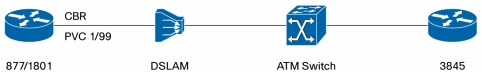
Figure 2 shows a graphic of a single PVC with the CBR CoS.
Figure 2. Single PVC with CBR Class of Service
In this scenario, PVC is defined with the CBR service category having the PCR value of 1500 kbps. Two different classes are defined to classify the voice and critical data information, and then bandwidth guarantee is provided to those classes using a service policy. All other nonclassified traffic falls into the default class, which uses Fair-queue for congestion management.
Following are the details on the bandwidth allocation for different applications:
• Class RT: Strict priority bandwidth of 400 kbps using LLQ
• Class MC: Assured bandwidth of 200 kbps using CBWFQ
But as per the setting on the DSLAM profile, the line trains up at only 832 kbps. Because of this change, the CPE automatically downgrades the PCR rate of the CBR PVC to 832 kbps.
Following is the snapshot of the notification sent on the console:
ADSL_877#
*Mar 21 10:11:56.715: %LINK-3-UPDOWN: Interface ATM0, changed state to up
*Mar 21 10:11:57.715: %LINEPROTO-5-UPDOWN: Line protocol on Interface ATM0, changed state to up
*Mar 21 10:12:02.447: %DSLSAR-1-DOWNGRADEDBW: PCR and SCR for VCD 1 (1/99) has been reduced to 832k due to insufficient upstream bandwidth
To confirm the congestion management mechanism after the downgrade of the PCR rate, three different streams with the following specification were sent:
Traffic matching the RT class (Voice): 370 PPS (Resultant Layer 3 Throughput sent = PPS*8*Packet size = 370*8*121 = 358 Kbps)
Traffic matching the MC class (Data): 200 PPS (Resultant Layer 3 Throughput sent = PPS*8*Packet size = 200*8*121 = 193 Kbps)
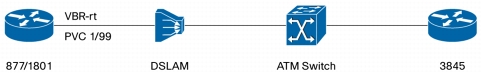
Figure 3 shows a graphic of a single PVC with VBR-rt CoS.
Figure 3. Single PVC with VBR-rt Class of Service
In this scenario, the PVC is defined with VBR-rt service category having a PCR value of 1500 kbps and SCR value of 1500 kbps. Two different classes are defined to classify the voice and critical data information, and then bandwidth guarantee is provided to those classes using a service policy. All other nonclassified traffic falls into the default class, which uses Fair-queue for congestion management.
Following are the details on the bandwidth allocation for different applications:
• Class RT: Strict priority bandwidth of 400 kbps using LLQ
• Class MC: Assured bandwidth of 200 kbps using CBWFQ
But as per the setting on the DSLAM profile, the line trains up at only 832 kbps. Because of this change, the CPE automatically downgrades the PCR rate and SCR rate of the VBR-rt PVC to 832 kbps.
Following is the snapshot of the notification sent on the console:
ADSL_877#
*Mar 21 10:11:56.715: %LINK-3-UPDOWN: Interface ATM0, changed state to up
*Mar 21 10:11:57.715: %LINEPROTO-5-UPDOWN: Line protocol on Interface ATM0, changed state to up
*Mar 21 10:12:02.447: %DSLSAR-1-DOWNGRADEDBW: PCR and SCR for VCD 1 (1/99) has been reduced to 832k due to insufficient upstream bandwidth
To confirm the congestion management mechanism after the downgrade of the PCR and SCR, three different streams with the following specification were sent:
Traffic matching the RT class (Voice): 370 PPS (Resultant Layer 3 Throughput sent = PPS*8*Packet size = 370*8*121 = 358 Kbps)
Traffic matching the MC class (Data): 200 PPS (Resultant Layer 3 Throughput sent = PPS*8*Packet size = 200*8*121 = 193 Kbps)
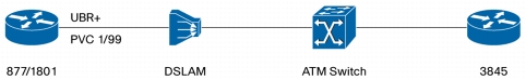
Figure 4 shows a graphic of a single PVC with UBR+ CoS.
Figure 4. Single PVC with UBR+ Class of Service
In this scenario, a PVC is defined with UBR+ service category having a PCR value of 1500 kbps and a MCR value of 1500 kbps. Two different classes are defined to classify the voice and critical data information, and then bandwidth guarantee is provided to those classes using a service policy. All other nonclassified traffic falls into the default class, which uses Fair-queue for congestion management.
Following are the details on the bandwidth allocation for different applications:
• Class RT: Strict priority bandwidth of 400 kbps using LLQ
• Class MC: Assured bandwidth of 200 kbps using CBWFQ
But as per the setting on the DSLAM profile, the line trains up at only 832 kbps. Because of this change, the CPE automatically downgrades the PCR rate and MCR rate of the UBR+ PVCs to 832 kbps.
Following is the snapshot of the notification sent on the console:
ADSL-877#
*May 2 17:12:43.367: %LINK-3-UPDOWN: Interface ATM0, changed state to down
*May 2 17:14:01.627: %LINK-3-UPDOWN: Interface ATM0, changed state to up
*May 2 17:14:02.627: %LINEPROTO-5-UPDOWN: Line protocol on Interface ATM0, changed state to up
*May 2 17:14:07.215: %DSLSAR-1-DOWNGRADEDBW: PCR and SCR for VCD 1 (0/34) has been reduced to 832k due to insufficient upstream bandwidth
ADSL-877#
To confirm the congestion management mechanism after the downgrade of the PCR and MCR, three different streams with the following specification were sent:
Traffic matching the RT class (Voice): 370 PPS (Resultant Layer 3 Throughput sent = PPS*8*Packet size = 370*8*121 = 358 Kbps)
Traffic matching the MC class (Data): 200 PPS (Resultant Layer 3 Throughput sent = PPS*8*Packet size = 200*8*121 = 193 Kbps)
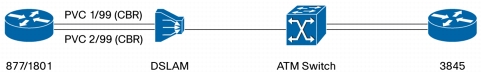
Figure 5 shows a graph of data service with multiple PVCs.
Figure 5. Data Service with Multiple PVCs
Two point-to-point PVCs are defined with a CBR service category, with one having the PCR rate as 400 kbps and the other with 600 kbps. Two different classes are defined to classify the voice and critical data information. All other nonclassified traffic falls into the default class, which uses Fair-queue for congestion management.
Then the same service policy providing the bandwidth guarantee with these defined classes is configured on both the PVCs.
Following are the details on the bandwidth allocation for different applications:
• Class RT: Strict priority bandwidth of 150 kbps using LLQ
• Class MC: Assured bandwidth of 100 kbps using CBWFQ
But as per the setting on the DSLAM profile, the line trains up at only 832 kbps. Because of this change, CPE is able to grant the requested bandwidth to the first PVC alone, that is, 400 kbps. The second PVC, which requested 600 kbps, is provided only the remaining 432 kbps as the PCR rate.
Following is the snapshot of the notification sent on the console:
ADSL_877#
*Mar 22 01:01:00.671: %LINK-3-UPDOWN: Interface ATM0, changed state to up
*Mar 22 01:01:01.671: %LINEPROTO-5-UPDOWN: Line protocol on Interface ATM0, changed state to up
*Mar 22 01:01:05.075: %DSLSAR-1-DOWNGRADEDBW: PCR and SCR for VCD 2 (2/99) has been reduced to 432k due to insufficient upstream bandwidth
To confirm the congestion management mechanism after the downgrade of the PCR rate, three different streams with the following specification were sent on each PVC simultaneously:
PVC 1:
Traffic matching the RT class (Voice): 370 PPS (Resultant Layer 3 Throughput sent = PPS*8*Packet size = 125*8*121 = 121 Kbps)
Traffic matching the MC class (Data): 200 PPS (Resultant Layer 3 Throughput sent = PPS*8*Packet size = 100*8*121 = 97 Kbps)
Scenario 3 - Data and Voice Services with Multiple PVCs
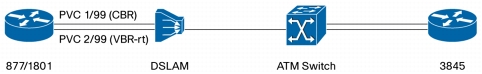
Figure 6 shows a graphic of data and voice services with multiple PVCs.
Figure 6. Data and Voice Services with Multiple PVCs
Two point-to-point PVCs are configured with a CBR and VBR-rt service category .The PCR rate for the CBR PVC is 400 kbps, and the PCR and SCR rate for the VBR-rt PVC is 700 kbps. Two different classes are defined to classify the voice and critical data information. All other nonclassified traffic falls into the default class, which uses Fair-queue for congestion management.
Then the same service policy providing the bandwidth guarantee with these defined classes is configured on both the PVCs.
Following are the details on the bandwidth allocation for different applications:
• Class RT: Strict priority bandwidth of 150 kbps using LLQ
• Class MC: Assured bandwidth of 100 kbps using CBWFQ
But as per the setting on the DSLAM profile, the line trains up at only 832 kbps. Because of this change, CPE is able to grant the requested bandwidth to the first PVC alone, that is, 400 kbps. The second PVC, which requested 700 kbps for both PCR and SCR, is provided only the remaining 432 kbps as the PCR and SCR rate.
Following is the snapshot of the notification sent on the console:
ADSL_877#
*Mar 22 01:01:00.671: %LINK-3-UPDOWN: Interface ATM0, changed state to up
*Mar 22 01:01:01.671: %LINEPROTO-5-UPDOWN: Line protocol on Interface ATM0, changed state to up
*Mar 22 01:01:05.075: %DSLSAR-1-DOWNGRADEDBW: PCR and SCR for VCD 2 (2/99) has been reduced to 432k due to insufficient upstream bandwidth
To confirm the congestion management mechanism after the downgrade of the PCR rate and SCR rate, three different streams with the following specification were sent on each PVC simultaneously:
PVC 1:
Traffic matching the RT class (Voice): 370 PPS (Resultant Layer 3 Throughput sent = PPS*8*Packet size = 125*8*121 = 121 Kbps)
Traffic matching the MC class (Data): 200 PPS (Resultant Layer 3 Throughput sent = PPS*8*Packet size = 100*8*121 = 97 Kbps)
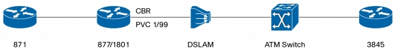
Scenario 4: Deploying Cisco ISR with an External DSL Modem
Figure 7. Deploying Cisco ISR with an External DSL Modem
In this scenario, a Cisco 877 or 1801 Integrated Services Router acts as an external modem functioning in transparent bridging mode (Figure 7). The router is connected to a Cisco 871 ISR with a FastEthernet interface as the WAN interface.
In typical deployments, Cisco 871 ISRs normally used behind a modem (cable or DSL modem) are not able to detect the congestion; hence turning on the queuing mechanism (LLQ/CBWFQ) may not produce the desired effect. Cisco therefore recommends that you apply class-based traffic shaping (CBTS) so that the traffic flow matches the modem characteristics (Cisco 877 and 1801 ISRs) before we can apply LLQ/CBWFQ on the Cisco 871.
The PVC on Cisco 877 and 1801 ISRs is defined with a CBR service category having the PCR value of 1500 kbps.
Two different classes are defined on the Cisco 871 to classify the voice and critical data information, and then bandwidth guarantee is provided to those classes using a service policy. All other nonclassified traffic falls into the default class, which uses Fair-queue for congestion management.
Following are the details on the bandwidth allocation for different applications:
• Class RT: Strict priority bandwidth of 400 kbps using LLQ
• Class MC: Assured bandwidth of 200 kbps using CBWFQ
• Class default: Fair-queue
A parent policy is defined with an average shaping rate of 832 kbps .Then the service policy defined previously (with different classes for voice and critical data) is used as the child policy under the parent policy. This method of referencing a child policy under another parent policy is defined as hierarchical QoS.
By following the previously defined deployment method, Cisco 871 ISRs get synchronized to external modem characteristics and the queuing mechanism achieves the expected results.
But as per the setting on the DSLAM profile, the line trains up at only 832 kbps. Because of this change, the Cisco 877 and 1801 ISRs automatically downgrade the PCR rate of the CBR PVCs to 832 kbps.
Following is the snapshot of the notification sent on the console:
877#
*May 8 06:03:55.167: %LINK-3-UPDOWN: Interface ATM0, changed state to up
*May 8 06:03:56.167: %LINEPROTO-5-UPDOWN: Line protocol on Interface ATM0, changed state to up
*May 8 06:04:01.575: %DSLSAR-1-DOWNGRADEDBW: PCR and SCR for VCD 1 (17/75) has been reduced to 832k due to insufficient upstream bandwidth
To confirm the congestion management mechanism after the downgrade of the PCR rate, three different streams with the following specification were sent on the PVC:
Traffic matching the RT class (Voice): 370 PPS (Resultant Layer 3 Throughput sent = PPS*8*Packet size = 125*8*121 = 121 Kbps)
Traffic matching the MC class (Data): 200 PPS (Resultant Layer 3 Throughput sent = PPS*8*Packet size = 100*8*121 = 97 Kbps)
Scenario 5 - Tuning of tx-ring and queue-depth Commands on the Multimode VDSL2 and ADSL2+ Modules and Platforms
The objective of the tuning is to minimize latency for voice traffic over an ADSL link. The recommended configuration guideline for queue-depth when used together with tx-ring-limit follows:
* Please refer to section 3.2.2 for details of the tx-ring-limit and queue-depth implementations.
With the voice traffic requirement, a low tx-ring-limit value of 2 is chosen. Given that the typical size of the low-priority data traffic with this connection is 768 bytes, queue-depth value is calculated as 15 using this formula.