This document is meant to be used for successfully deploying Cisco Prime™ Infrastructure. The assumption is that the basic wired and wireless network is already deployed. Cisco Prime Infrastructure will be used to manage, modify, or enhance the existing network. This guide has been updated for Cisco Prime Infrastructure 2.0.
Introduction
Combining the wireless functionality of Cisco Prime Network Control System (NCS) with Cisco Prime LAN Management Solution (LMS), Cisco Prime Infrastructure simplifies and automates many of the day-to-day tasks associated with deploying, maintaining, and managing the end-to-end network infrastructure from a single pane of glass. The new converged solution delivers many of the existing wireless capabilities for RF management, user access, reporting, and troubleshooting along with wired lifecycle functions such as discovery, inventory, configuration and image management, plug and play, integrated best practices, and reporting.
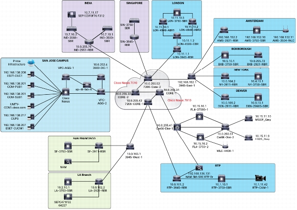
The image above shows a typical network diagram of a global enterprise that has many sites with varying sizes. You may see traffic coming from one site to another, as well as to and from sites to headquarters. How can we measure which site is consuming most of the WAN bandwidth? Which site has the worst user experience from an application point of view? Which site has more wired clients compared to wireless clients? This is just a partial list of questions that a network engineer could have and that can be easily answered with Cisco Prime Infrastructure.
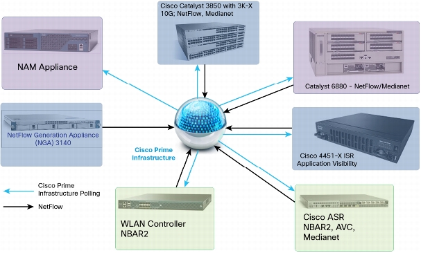
If you have an Assurance add-on license, you will be able to get an aggregated view from all the data sources in your network as shown in the following figure:
As we can see, Cisco Prime Infrastructure polls some of the devices using Simple Network Management Protocol (SNMP), and collects NetFlow from other data sources directly. In case of Cisco Prime Network Analysis Module (NAM), Cisco Prime Infrastructure collects all the information from the NAM natively. However, the NetFlow Generation Appliance (NGA) sends NetFlow to Cisco Prime Infrastructure. Routers and switches capable of NetFlow and medianet can be enabled and configured by Cisco Prime Infrastructure to get application visibility for the ones that flow through them.
Installation
The Cisco Prime Infrastructure software runs on either a dedicated Cisco Prime Appliance (PRIME-NCS-APL-K9) or on any server running VMware ESX/ESXi. The Cisco Prime Infrastructure software image does not support the installation of any other packages or applications on this dedicated platform. The Cisco Prime Infrastructure application comes preinstalled on a physical appliance with various performance characteristics.
Prerequisites
Cisco Prime Infrastructure runs on a 64-bit, Red Hat Linux Enterprise Server 5.4 operating system. You cannot install Cisco Prime Infrastructure on a standalone operating system such as Red Hat Linux, as Cisco Prime Infrastructure is shipped as a physical or virtual appliance that comes preinstalled with a secure and hardened version of Red Hat Linux as its operating system.
Server Requirements
Cisco Prime Infrastructure has two deployment options: Virtual appliance in the form of an Open Virtualization Archive (OVA) file, and hardware appliance, also known as the Cisco Prime Appliance. The virtual appliance is an OVA file that can be deployed on ESXi 5.x (ESXi 4.x is not recommended due to file-size limitations). The following table lists the hardware requirements for the virtual appliance based on wired/wireless scale.
Virtual Appliance Size
Virtual CPU (vCPU)***
Memory (DRAM)
HDD Size
Throughput
(Disk I/O)**
Max Concurrent
Clients/Users
API Clients
Express
4
12 GB
300 GB
200 MBps
5
2
Custom Express*
8
16 GB
600 GB
200 MBps
5
2
Standard
16
16 GB
900 GB
200 MBps
25
5
Pro
16
24 GB
1200 GB
200 MBps
25
5
* Custom Express is not a separate OVA. You can take the Express OVA and customize it with the parameters for Custom Express mentioned in the preceding table.
** Refer to "Logging In to Cisco Prime Infrastructure for the First Time" for more details on calculating IOPS.
*** VMware refers to CPU as pCPU and vCPU. pCPU or `physical' CPU in its simplest terms refers to a physical CPU core i.e. a physical hardware execution context (HEC) if hyper-threading is unavailable or disabled. If hyperthreading has been enabled then a pCPU would constitute a logical CPU. This is because hyperthreading enables a single processor core to act like two processors i.e. logical processors. So for example, if an ESX 8-core server has hyper-threading enabled it would have 16 threads that appear as 16 logical processors and that would constitute 16 pCPUs." So in PI when we say vCPU, we mean Numbers of Threads (assuming Hypter-threading is enabled) that are available for execution to the actual VM. So a 2, quad core, hyper-threading enabled CPUs on the host will give the 16vCPUs to vmware. [2 x 4 (Quad Core) = 8; 8 x 2 (for HT) = 16].
Special Sizing Note:
• If you have been using a Medium OVA from prior versions of Cisco Prime Infrastructure (1.2 or 1.3), and have the same number of devices to manage with Cisco Prime Infrastructure 2.0 without significant change in your usage, you can upgrade to Cisco Prime Infrastructure 2.0. You do not have to increase the resource pool for the OVA in this case.
• Cisco Prime Appliance is equivalent to a standard virtual appliance for sizing purposes. If you are currently using the Cisco Prime Appliance to manage more devices than is supported under standard, and have not significantly added more devices or turned on new features, you can continue to use the Cisco Prime Appliance to manage these devices.
Cisco Prime Appliance comes with the specifications shown in the following table:
Physical
Appliance
Physical CPU
Memory
(DRAM)
HDD Size
Throughput
(Disk I/O)
Max Concurrent
Clients/Users
API Clients
Cisco Prime Appliance
8 Cores
(16 Threads)
32 GB
900 GB
(4x300GB RAID5)
200 MBps
25
5
Client Requirements
The following table shows all the supported browsers that can be used to access Cisco Prime Infrastructure. Please use the Cisco Prime Infrastructure 2.0 Quick Start Guide for the latest client requirements.
Supported Browser
Browser Version
Additional Notes
Internet Explorer
8.0 or 9.0
Microsoft Internet Explorer 8.0 or 9.0 with Google Chrome Frame plug-in (users logging in to the simplified Lobby Ambassador interface do not need the plug-in).
Mozilla Firefox
Firefox 22 or later
Latest Firefox version may be used, but it may not be tested depending on when it was released.
Latest Chrome version may be used, but it may not be tested depending on when it was released.
TIP:
• It is strongly recommended to use a client with at least 4 GB or more. Adding more memory will definitely enhance the end-user experience.
• If you experience any issues with some of the pages not showing up, please try clearing the browser and flash cache as well as installing the latest version of flash available.
Server Sizing Matrix
The following table should help users to pick the right OVA size image for Cisco Prime Infrastructure Virtual Appliance. Users with Cisco Prime Appliance (physical) should use the "Standard" column:
Device Type
Express
Custom Express*
Standard
Pro
Network Devices
• Max Unified APs
300
2,500
5,000
20,000
• Max Wired Devices
300
1,000
6,000
13,000
• Max Autonomous APs
300
500
3,000
3,000
• Max NAMs
5
5
500
1,000
Clients
• Max Wireless (Roaming) Clients
4,000
30,000
75,000
200,000
• Max Changing (Transient) Clients
1,000
5,000
25,000
40,000
• Max Wired Clients
6,000
50,000
50,000
50,000
Monitoring
• Max Interfaces
12,000
50,000
250,000
350,000
• Max NetFlow Rate (flows/sec)
3,000
3,000
16,000
80,000
• Max Events (events/sec)
100
100
300
1,000
• Max NAM Data Polling Enabled
5
5
20
40
System
• Max Number of Sites per Campus
200
500
2,500
2,500
• Max Virtual Domains
100
500
1,000
1,000
• Max Groups (Total): User-Defined + Out of the Box + Device Groups + Port Groups
50
100
150
150
• Max Concurrent GUI Clients
5
10
25
25
• Max Concurrent API Clients
2
2
5
5
* Custom Express is not a separate OVA. You can take the Express OVA and customize it with the parameters for Custom Express mentioned in the preceding table.
Installing the Cisco Prime Infrastructure Virtual Appliance
Cisco Prime Infrastructure is delivered as a virtual appliance or OVA file. OVA files allow you to easily deploy a prepackaged virtual machine (VM) - an application along with a database and an operating system. Please follow the link below for detailed instruction on installing Cisco Prime Infrastructure Virtual Application.
Installing Cisco Prime Infrastructure on a Physical Appliance
Cisco Prime Infrastructure 2.0 comes preinstalled on the PRIME-NCS-APL-K9 physical appliance. The Cisco Prime Infrastructure 2.0 software image does not support the installation of any other packages or applications on this dedicated platform. If for some reason the appliance comes without any software, the application may be installed from the DVD that comes with it. Once the server boots up, the procedure will be similar to the procedure described for a virtual appliance. More information on installing Cisco Prime Infrastructure on a physical appliance can be found at http://www.cisco.com/en/US/docs/net_mgmt/prime/infrastructure/2.0/install/guide/Cisco_PI_Hardware_Appliance_Installation_Guide.html.
Starting/Stopping Cisco Prime Infrastructure Services
In normal circumstances, you will not have to stop or start NCS services. The services will start automatically once installation is complete, and no manual startup of services is required. If there is a need to restart the services for some reason, the following commands may be executed by the admin user from the command-line interface (CLI):
pi1.cisco.com/admin# ncs stop - Stops the Cisco Prime Infrastructure server
pi1.cisco.com/admin# ncs status - Shows the Cisco Prime Infrastructure server status
pi1.cisco.com/admin# ncs start - Starts the Cisco Prime Infrastructure server
Logging In to Cisco Prime Infrastructure for the First Time
Once the Cisco Prime Infrastructure server has been installed and configured, it is now ready to be accessed from the web. The server URL would be https://server_hostname or https://ip.ad.dr.ess. In Cisco Prime Infrastructure 2.0, log in using the following credential for the very first time:
Username: root
Password: <the root password is the one that was entered during the install script>
After the server has been configured, it is advisable to log in with a non-root user to keep the root user for system level configurations as and when needed. More updated information can be found at Cisco Prime Infrastructure 2.0 Quick Start Guide at Logging into the Cisco Prime Infrastructure User Interface.
Accessing Cisco Prime Infrastructure Through the CLI
In normal circumstances, you may not need to access the CLI, but if there is a need for access to some service requirements, the Cisco Prime Infrastructure server may be accessed through Secure Shell Protocol Version 2 (SSH2) by the admin user. The admin user is provided with a Cisco IOS® Software-like shell, which is the preferred shell for carrying out most operational tasks. The password for this admin user is configured during the initial installation and configuration, as mentioned in the "Installing the Cisco Prime Infrastructure OVA" section. Please note that the root password that is prompted in the install script is only for web access and not access to the CLI.
How to Enable the CLI Root User in the Cisco Prime Infrastructure Server
The root user is not enabled by default, but you can enable the root user for the first time using the root_enable command at the admin console. Once the root user is enabled, log out of the admin shell and log in using the root user and the previously defined password for root.
Verifying IOPS for Cisco Prime Infrastructure Virtual Machine
Until Cisco Prime Infrastructure 1.3, there was no easy way to verify data store IOPS (input/output operations per second) for the virtual infrastructure. With the addition of the following new command, users can now verify the raw performance before proceeding any further. Here is how to use the command (from the root shell):
Note that the recommended value for the IOPS is 200 MBps as mentioned in the server requirement section.
Licensing
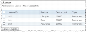
After you have installed Cisco Prime Infrastructure for the first time you may access the lifecycle and assurance features using the built-in evaluation license that is available by default. The default evaluation license is valid for 60 days for 100 devices. To continue using the system, you will need to purchase the base license and the corresponding feature license before the evaluation license expires. Cisco Prime Infrastructure 2.0 can be ordered through a Cisco partner, distributor, or using the standard Cisco® ordering tools at http://www.cisco.com/go/ordering. More information about getting the license files can be found in the Cisco Prime Infrastructure 2.0 Ordering and Licensing Guide. Cisco Prime Infrastructure licenses are locked to a specific Cisco Prime Infrastructure instance based on a unique device identifier (UDI) for a physical appliance or a virtual unique device identifier (VUDI) for a virtual appliance (figure above). The identifier can be found within the Cisco Prime Infrastructure user interface under Administration > Licenses. Once you have obtained the license file (.lic), you are now ready to apply it. License files can be added to Cisco Prime Infrastructure by going to Administration > Licenses > Files > License Files. The license files should look like the figure on the right. For more information on Cisco Prime Infrastructure licensing you can also refer to the Cisco Prime Infrastructure 2.0 Quick Start Guide.
Configuring Backup
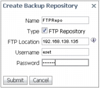
At this point, you do not have any data, but soon you will start accumulating lots of data. It is strongly advisable to configure the backup plan in a more proactive manner. Backup can be configured by navigating to Administration > Background Tasks > Other Background Tasks (Section) > Prime Infrastructure Server Backup. You can either use the default repository, default Repo, or create an external backup repository by clicking the Submit button as shown in the figure (below). Enter FTP credentials and other relevant information to create this new remote backup repository.
Advanced System Settings
There are some settings in Cisco Prime Infrastructure that need to be looked at closely before you start to manage the network. Optimal settings are already configured, but you may need to tweak the settings based on the network you are managing. You can access the settings by navigating to Administration > System Settings.
Data Retention
This menu item (Administration > System Settings) allows you to specify how much data is to be stored in Cisco Prime Infrastructure. By default you can store up to 7 days of raw data and 1 year's worth of aggregated data. You can increase these numbers based on the hard drive space that is provided to Cisco Prime Infrastructure. You can find more details on such system settings in Cisco Prime Infrastructure Best Practices.
High Availability
The Cisco Prime Infrastructure High Availability (HA) implementation allows one primary Cisco Prime Infrastructure server to failover to one secondary (backup) Cisco Prime Infrastructure server. A second server is required that has sufficient resources (CPU, hard drive, network connection) in order to take over Cisco Prime Infrastructure operation in the event that the primary Cisco Prime Infrastructure system fails. In Cisco Prime Infrastructure, the only HA configuration is supported is 1:1 - 1 primary system, 1 secondary system.
The size of the secondary server must be larger than or equal to that of the primary server; for example, if the primary Cisco Prime Infrastructure server is the medium OVA, then the secondary Cisco Prime Infrastructure server must be the medium or large OVA.
HA Setup
The primary and secondary server can be a mix of a physical and a virtual appliance. For example, if the primary Cisco Prime Infrastructure server is a physical appliance, the secondary server can be either a physical appliance or a large OVA virtual appliance; for example, the server configuration and sizing of large OVA is the same as the physical appliance. Customers must be running the same version of Cisco Prime Infrastructure on both the primary and secondary Cisco Prime Infrastructure servers. The Cisco Prime Infrastructure HA feature is transparent to the wireless controller, that is, there is no software version requirement for the Cisco Wireless LAN Controller (WLC), access points (APs), and the Cisco Mobility Services Engine (MSE).
Licensing
A RTU (tight-to-use) license is required to deploy Cisco Prime Infrastructure in an HA implementation. Apart from this, only one Cisco Prime Infrastructure server license needs to be purchased. There is no need to purchase a license for the secondary Cisco Prime Infrastructure server. The secondary server will use the license from the primary when a failover occurs. The secondary node will simulate the UDI information of the primary; thus the secondary server will be able to use the synchronized license from the primary server when the secondary server is active. The same Cisco Prime Infrastructure license file resides on both the primary and secondary Cisco Prime Infrastructure servers. Since the Cisco Prime Infrastructure Java Virtual Machine (JVM) is only running on the primary or secondary (not both), the license file is only active on one system at a given point in time.
Cisco Prime Infrastructure High Availability Setup
Cisco Prime Infrastructure HA can also be deployed with geographic separation of the primary and secondary servers. This type of deployment is also known as disaster recovery or geographic redundancy.
HA Modes
There are two HA modes: failover and failback. Let's take a look at each of them in detail.
Failover
After initial deployment of Cisco Prime Infrastructure, the entire configuration of the primary Cisco Prime Infrastructure server is replicated to the host of the secondary Cisco Prime Infrastructure server. During normal operation (that is, when the primary Cisco Prime Infrastructure server is operational), the database from the primary server is replicated to the secondary Cisco Prime Infrastructure server. In addition to the database replication, application data files are also replicated to the secondary Cisco Prime Infrastructure server. Replication frequency is 11 seconds (for real-time files) and 500 seconds (for batch files).
Failback
When the issues on the server that host the primary Cisco Prime Infrastructure server have been resolved, failback can be manually initiated. Once this is done, the screen is displayed on the secondary Cisco Prime Infrastructure server. When you initiate failback, the Cisco Prime Infrastructure database on the secondary Cisco Prime Infrastructure server and any other files that have changed since the secondary Cisco Prime Infrastructure server took over Cisco Prime Infrastructure operation are synchronized between the secondary and the primary Cisco Prime Infrastructure servers. Once database synchronization has been completed, the primary Cisco Prime Infrastructure JVM is started by the primary Health Monitor (HM). When the primary Cisco Prime Infrastructure JVM is running, the preceeding screen is displayed on the secondary HM.
Manual/Automatic Options
Automatic Failover
Automatic failover is a much simpler process. The configuration steps are the same except that automatic failover is selected. Once automatic failover is configured, the network administrator does not need to interact with the secondary HM in order for the failover operation to take place. Only during failback is human intervention required.
Primary Failure Example - Manual Failover
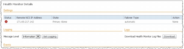
In this example, the secondary Cisco Prime Infrastructure server was configured with manual failover. For example, the network administrator is notified through email that the primary Cisco Prime Infrastructure server has experienced a down condition. The Health Monitor on the secondary Cisco Prime Infrastructure server detects the failure condition of the primary Cisco Prime Infrastructure server. Because manual failover has been configured, the network administrator needs to manually trigger the secondary Cisco Prime Infrastructure server to take over Cisco Prime Infrastructure functionality from the primary Cisco Prime Infrastructure server. This is done if you log in to the secondary HM. Even though the secondary Cisco Prime Infrastructure server is not running, you can connect to the secondary HM using the following syntax: https://<Secondary_PI_IP_Address>:8082/.
The secondary HM displays messages in regard to events that are seen. Because manual failover has been configured, the secondary HM waits for the system administrator to invoke the failover process. Once manual failover has been chosen, the message is displayed as the secondary Cisco Prime Infrastructure server starts. Once the failover process has been completed, which means that the Cisco Prime Infrastructure database replication process is completed and the secondary Cisco Prime Infrastructure JVM process has started, then the secondary Cisco Prime Infrastructure server is the active Cisco Prime Infrastructure server.
Health Monitor on the secondary Cisco Prime Infrastructure server provides status information on both the primary and secondary Cisco Prime Infrastructure servers. Failback can be initiated through the secondary HM once the primary Cisco Prime Infrastructure server has recovered from the failure condition. The failback process is always initiated manually so as to avoid a flapping condition that can sometimes occur when there is a network connectivity problem. More details on how to deploy Cisco Prime Infrastructure 2.0 HA can be found at http://www.cisco.com/en/US/docs/net_mgmt/prime/infrastructure/2.0/administrator/guide/config_HA.html.
Upgrade and Data Migration from Previous Versions
Although it may sound trivial to upgrade from Cisco Prime Infrastructure 1.x, there are some instances where we still recommend users to continue using version 1.x. Please note that these recommendations are only specific to Cisco Prime Infrastructure 2.0, and may change once later versions are out in 2.x train.
• If you have been using Cisco Prime Infrastructure 1.x Small OVA, an inline upgrade to Cisco Prime Infrastructure 2.0 is not supported. Recommendation in this case is to migrate instead; that is, back up 1.x after applying the relevant patch and then restore onto a freshly installed Cisco Prime Infrastructure 2.0 Express OVA. You will most likely need to increase CPU/memory based on the new requirement for Cisco Prime Infrastructure 2.0 as mentioned in the preceding Server Sizing Matrix.
• If you are using Cisco Prime Infrastructure 1.3.x managing an AireOS 7.4-based wireless infrastructure, please continue to stay with the Cisco Prime Infrastructure 1.3.x train. Only if you are going to deploy Converged Access infrastructure do you then need to upgrade to Cisco Prime Infrastructure 2.0.
• If you are using Cisco Prime Infrastructure 1.4 managing an AireOS 7.5-based wireless infrastructure (due to 802.11ac support), please continue to stay with Cisco Prime Infrastructure 1.4 until the 1.4.1 train. The next significant release with AireOS 7.5 support would be Cisco Prime Infrastructure 2.1.
Upgrading to Cisco Prime Infrastructure 2.0
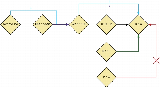
Users can upgrade to Cisco Prime Infrastructure 2.0 only from one of the following supported versions:
Direct migration from WCS 7.x to Cisco Prime Infrastructure 2.0 is NOT possible. We strongly recommend upgrading your WCS to 7.0.230.0 (for data integrity) or higher before attempting to migrate to NCS. Users will first need to do an intermediary migration to NCS 1.1.1.24, and then do an inline upgrade (or migration) to Cisco Prime Infrastructure 2.0.
Cisco Prime LMS features were reevaluated for usefulness, usability, and value. Some features are redesigned and have transitioned, some are on the road map, others are to be determined by customers, and a few are being deprecated. Also see the Cisco Prime Infrastructure LMS Functional Support Reference for details on which LMS data sets will be migrated or backed up into Cisco Prime Infrastructure 2.0.
LMS 2.x
LMS 2.x has reached its end of life, and that is why upgrading from LMS 2.x to Cisco Prime Infrastructure 2.0 is not supported (nor is it recommended). Customers could export their device inventory into a comma-separated value (CSV) file for their own records. Alternatively customers can also start using Cisco Prime Infrastructure 2.0 for basic network management type features. Even though data migration is not possible, you should still be able to manage your network in no time starting with discovery from within Cisco Prime Infrastructure 2.0.
LMS 3.x
LMS 3.x has also reached end of engineering. If you are currently using basic management features such as monitoring, configuration management, inventory management, software image management, and fault management, you should consider upgrading to Cisco Prime Infrastructure 2.0. Even though data migration is not possible, you should still be able to manage your network in no time starting with discovery from within Cisco Prime Infrastructure 2.0.
LMS 3.x customers requiring features like CiscoView, Layer 2 topology, IP service-level agreements (IP SLAs), and VLAN management are recommended to run Cisco Prime Infrastructure 2.0 as a separate server side by side until equivalent features are being migrated into Cisco Prime Infrastructure 2.0.
LMS 4.x
LMS 4.x customers using basic management features like monitoring, syslogs, configuration management, inventory management, software image management, and fault management should consider migrating to Cisco Prime Infrastructure 2.0.
LMS 4.x customers requiring features like CiscoView, Layer 2 topology, IP SLAs, work centers, and VLAN management are recommended to run Cisco Prime Infrastructure 2.0 as a separate server side by side or to wait until all the features have been migrated into Cisco Prime Infrastructure 2.x.
Exporting Inventory from LMS 4.2.4 and Later
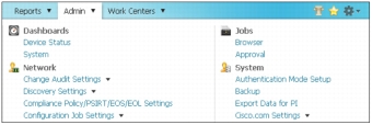
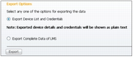
With LMS 4.2.4 (and later releases), there is an easy way from the web interface to export the device list with credentials, which can then be consumed by Cisco Prime Infrastructure. The device list can be exported from Administration > Export Data to Cisco Prime Infrastructure (under System).
Then select Export Device List and Credentials from the export options as shown in the following figure:
Importing into Cisco Prime Infrastructure 2.0
Once you have the exported the device list with credentials from LMS 4.2.4, it can be imported into Cisco Prime Infrastructure 2.0 by navigating to Operation > Device Work Center > Bulk Import as shown in the following figure:
LMS 4.2 Data Migration
If you have a need to migrate data from LMS 4.2.x, Cisco Prime Infrastructure 2.0 now allows you to import this successfully. The procedure for this is detailed as follows:
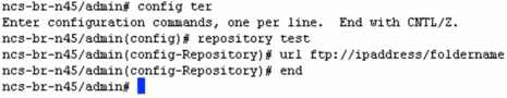
2. Configure the repository on Cisco Prime Infrastructure 2.0. It can be local or remote. The repository indicates where the backup file is located. You may configure a local (as previously mentioned) repository or a remote repository as shown below:
3. Once the repository is created, run the following command to see all the backup files:
admin# show repository <repository-name>
Import the LMS backup into Cisco Prime Infrastructure using the following command (in admin mode):
admin# Lms migrate repository <repository-name>
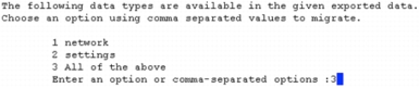
4. After Importing data from the LMS server to Cisco Prime Infrastructure 2.0, the restored data id categorized into four buckets:
1. Network data (mandatory)
• DCR (Device Credential Repository) import
• Static group import
• Dynamic group import
• LMS users import
• SWIM image import
• User-defined templates
2. Settings (mandatory) - MIBS Image import
3. User objects
4. Historic data (optional data)
Currently Cisco Prime Infrastructure 2.0 will only support import items 1 and 2 from the preceding list.
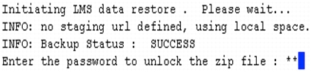
5. You will then be asked to enter the password for the .zip file (as shown below) that was created during export from LMS for security purposes.
6. You then need to enter Cisco Prime Infrastructure's web username and password to get the session for importing the LMS data.
7. Once the user has entered this command in the admin console, the system will validate the following conditions:
• Zip file validation
• Check sum validation
• Backupcontents.xml - it is used to display the buckets details
8. To migrate all the available data choose option 3 as shown above and let the system install Cisco Prime LMS 4.2.x data on your Cisco Prime Infrastructure 2.0 server.
Cisco Prime Infrastructure Device Packs and Software Updates
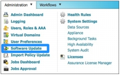
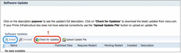
There was always the framework for allowing users to seamlessly download and install patches for Cisco Prime Infrastructure itself. Starting Cisco Prime Infrastructure 2.0, we will be pushing out patches using this mechanism. In order to check for software updates, navigate to Administrator > Software Update as shown in the figure (below).
Once you click that link, you will see the page as shown in the following figure. Going forward you will be able to check for software patches as well as device packs.
Simply click Check for Updates to see the availability. If available, select the update and click Install as shown in the preceding figure
Application Setup
Cisco Prime Infrastructure 1.x introduced a new lifecycle approach to managing your wired and wireless infrastructure. There are five phases in this lifecycle: design, deploy, operate, report, and administer. The details for each of these phases are briefly described in the following section.
Lifecycle Management
Design
In this phase, you can assess, plan, and create configurations required to roll out new network services and technologies. You can create templates used for monitoring key network resources, devices, and attributes. Default templates and best practice designs are provided for quick out-of-the-box implementation, automating the work required to use Cisco validated designs and best practices.
Deploy
In this phase, you can schedule the rollout and implementation of network changes. Changes may include published templates created in the design phase, software image updates, and support for user-initiated ad hoc changes and compliance updates. This accelerates service rollout, minimizes chances for errors, and is highly scalable.
Operate
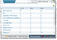
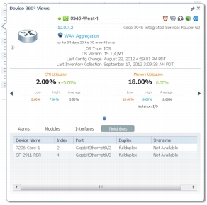
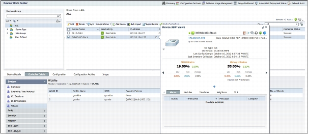
In this phase, you can utilize preconfigured dashboards to provide up-to-date status monitoring on the overall health of the network. Simple one-click workflows and 360-degree views enhance troubleshooting and reduce the time to resolve network issues. Unified alarm displays with detailed forensics provide actionable information and the ability to automatically open service requests with the Cisco Technical Assistance Center (TAC).
Report
In this phase, you can provide a wide variety of preconfigured reports for up-to-date information on the network, including detailed inventory, configuration, compliance, audit, capacity, end of sale, security vulnerabilities, and many more. Reports can be scheduled or run immediately, emailed, or saved as PDFs for future viewing purposes.
Administer
In this phase, you can provide an easy-to-use set of workflows that help to maintain the health of the application and keep devices, users, and the software up to date, allowing the IT staff to focus on other important activities.
Creating Groupings and Sites
Cisco Prime Infrastructure provides a very easy way to map each of the devices into its own site. There is also an ability to create groups based on predefined rules or criteria. Let's take a look at how to create sites and groups in Cisco Prime Infrastructure to help visualize applications in an intuitive manner.
Create Sites
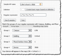
There are two way of creating sites. If your access points follow a very consistent naming convention, you can automatically create a site tree map based on the hostname. The image below shows how a device hostname separated by hyphens can be used as a delimiter to create a site map tree automatically.
To create automatic site hierarchies go to Design > Automatic Hierarchy Creation. Enter the AP Hostname and a suitable regular expression (or generate one as mentioned in the tip below). Click Test to see how the site is created from the hostname. Change the pull-down to map to the appropriate campus, building, floor, device, and so on.
TIP: After entering a sample hostname for an AP, you can click Create basic regex based on delimiter to automatically generate the regular expression.
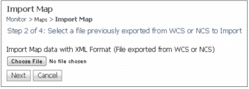
Import/Edit Maps from WCS/NCS to Cisco Prime Infrastructure
If you have already created sites for the wireless network in a previous version of WCS or NCS, you can export from those applications and import the information into Cisco Prime Infrastructure as well. You can go to Design > Site Map Design > Import Maps > Choose File (as shown in figure below). Once the file has been uploaded, all the sites will be automatically created by Cisco Prime Infrastructure.
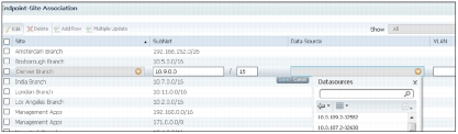
Associate Endpoints to Sites
Now that you have created all the sites where your network equipment is staged, it is time to map those sites to their respective subnets, data sources, and VLANs. This allows Cisco Prime Infrastructure to see the traffic flow, especially when it comes to application performance. In order to create an endpoint, you can go to Design > Endpoint-Site Association. The image below shows how various sites are mapped to their subnets. In addition to the subnet mask, you can also specify the default data source desired for that site in addition to the VLANs for those sites.
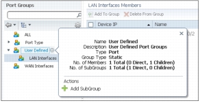
Create Port Groups
The next step in getting started with Cisco Prime Infrastructure is to create groups in addition to the default port groups that come preconfigured. Port groups creation can be accessed from Design > Port Grouping. If a custom port group needs to be created, you can hover over User Defined and click the plus sign icon to access a pop-up menu for adding a new group as shown in image below.
The WAN Interfaces port group is a special preconfigured port group. The interfaces in this group are your WAN interfaces that need to be actively monitored. In order to add WAN interfaces to this group, select all groups and filter the WAN interfaces based on your interfaces type, IP address, interface description, or any other attributes that are used to denote a WAN interface group. It is highly recommended to populate this group with the WAN interface to get the most out of this application.
Users and User Group Management
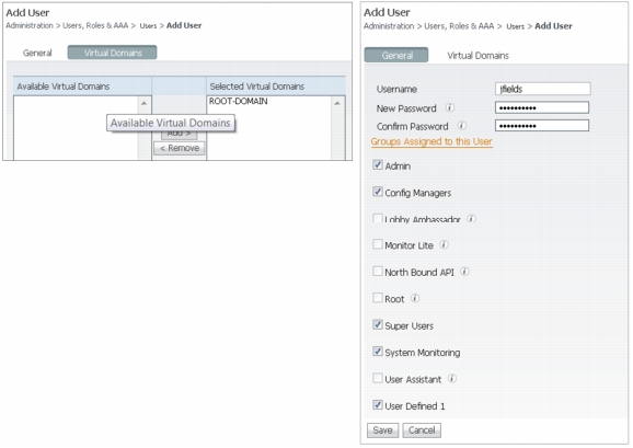
Adding New Users
As noted earlier, it is not advisable to use the root user to log in for normal use. New users and groups can be created by navigating to Administration > Users, Roles & AAA as shown in the preceding figures. It would help to chalk out what are the various levels at which you want to distribute the users, and to create those roles first. It doesn't really matter whether you create users or groups first. New users can be easily added by going to Administration > Users, Roles & AAA > Users > Add Users > Select "Add Users" from the drop-down on the right side. Once you get into the add user workflow, fill in the username, password, and local authorization for this user as shown in the figure below (right).
A virtual domain can also be assigned to the users when you define their roles by selecting the virtual domain on the left side and moving it to the right side as shown in the image below (left).
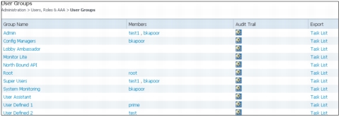
Creating User Groups
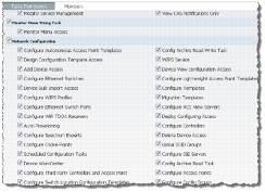
User groups are synonymous with roles. All the roles except the user-defined roles are preconfigured. User-defined groups can be modified by going to Administration > Users, Roles & AAA > User Groups > User Defined #. Other groups and roles cannot be modified, but you can add users to them, see the audit trail, and even export the TACACS+/RADIUS command sets by clicking the task list. User-defined roles can be modified by clicking the User Defined # link in the figure above (left). Once clicked, all the knobs on the user access controls are exposed as shown in the figure (below). You can select the whole category, for example, Network Configuration, or a few of the options within that category to customize the role. Once the group/role is created, multiple users can then be assigned to that group.
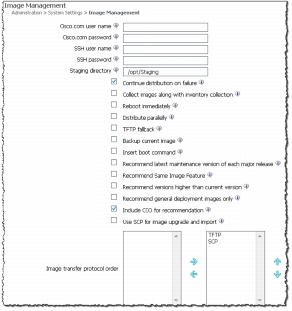
Image Management Settings
There aren't any mandatory settings required for software image management, but a number of knobs can be accessed from Administration > System Settings > Image Management as shown in figure (right). These include the team shared Cisco.com username/password, job failure handling options, image and configuration protocol options, and so on. Users are strongly recommended to glance through this page and set it up initially so that preferred preferences are applied when distributing images on managed devices. Images can easily be added to the local repository by choosing Operate > Software Image Management > Import. Follow the wizard to import images from Cisco.com directly.
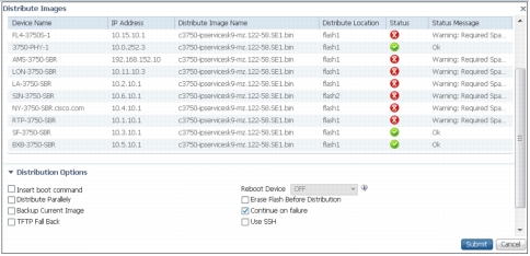
Images can be deployed to devices by going to Operate > Software Image Management. Select the image from the list (once it has been added to the repository) and click Distribute Images. Once the devices are selected to be upgraded/downgraded, a prerun status is shown, which avoids the job failure in the first place. You can also run Upgrade Analysis from the same place to get a report on this.
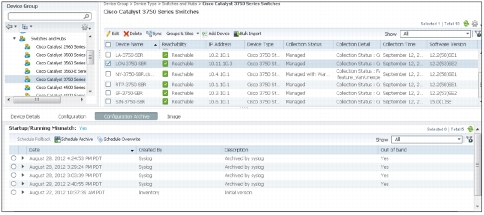
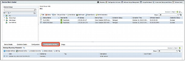
Configuration Archive Settings
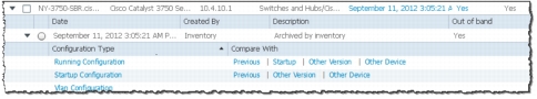
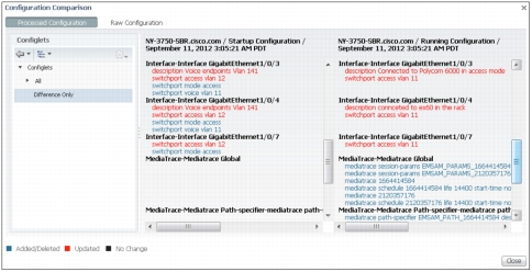
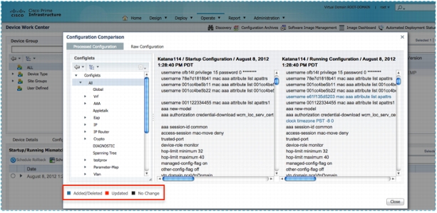
The Configuration Archive will be one of the most used portions from a daily operation point of view. It is highly recommended to go to Administration > System Settings > Configuration Archive. The Basic tab allows users to define protocol order, SNMP timeout, the number of days and the versions to retain, thread pool count, and other such variables. The Advanced tab allows users to define a command exclude list for each of the device family types. Once this is done, users may view and compare configurations by navigating to Operate > Configuration Archives (under the Device Work Center). Browse the device and open up the tree to see all the configuration versions that have been archived for this device as shown in the preceeding figure. When you click Compare there, you quickly see the color-coded configuration differences instantly as shown in same preceeding figure.
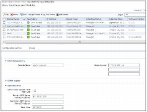
Configuring NTP and DNS for NAMs
It is extremely important to configure NTP and DNS for all the NAMs in your network. You can now configure those without going to the CLI or logging in to the individual NAM web GUIs. From the Cisco Prime Infrastructure Device Work Center, navigate to Device Group > Device Type > Cisco Interfaces and Modules. Click the name of the NAM on which you want to configure NTP/DNS, and then click Configure in the bottom pane. Now click Feature on the left (still in the bottom pane), and you will see a link for "system." Click it to see a form for this NAM that allows you to configure all the system-related information for a given NAM including NTP and DNS. The image on the left (above) shows where the NTP and DNS can be configured.
Connection to Cisco.com
Cisco.com connection is required for some of the advanced features such as Smart Interactions (TAC service requests, and support forums), importing software images, contract connection, and many others. It is vital for the Cisco Prime Infrastructure server to be able to connect to Cisco.com to pull the data for those reasons. There are two parts to making this work: proxy settings and Cisco.com user settings.
Proxy Settings
If Cisco Prime Infrastructure requires a proxy to connect to the Internet, you can enter the proxy information by going to Administration > System Settings > Proxy Settings. You can enable proxy settings and enter all the proxy information there. Authenticating proxies is also supported in Cisco Prime Infrastructure.
Cisco.com Settings
Once the proxy settings are configured, you can enter your Cisco.com credentials at the following places:
• Administration > System Settings > Image Management
• Administration > System Settings > Support Request Settings
Planning/Preparing the Network
Wireless Planning Tool
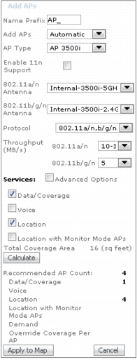
The built-in planning tool provides a way for network administrators to determine what is required in the deployment of a wireless network. As part of the planning process, various criteria are input into the planning tool. Complete these steps:
1. Specify the AP prefix and AP placement method (automatic versus manual).
2. Choose the AP type and specify the antenna for both the 2.4 GHz and 5 GHz bands.
3. Choose the protocol (band) and minimum desired throughput per band that is required for this plan.
4. Enable planning mode for advanced options for data, voice, and location. Data and voice provide safety margins for design help. Safety margins help design for certain RSSI thresholds, which is detailed in online help. The location with monitor mode factors in APs that could be deployed to augment location accuracy. The location typically requires a denser deployment than data, and the location check box helps plan for the advertised location accuracy.
5. Both the Demand and Override options allow for planning for any special cases where there is a high density of client presence such as conference rooms or lecture halls.
Generated proposal contains these:
• Floor plan details
• Disclaimer/scope/assumptions
• Proposed AP placement
• Coverage and data rate heat map
• Coverage analysis
Ports Used
The following table shows all the ports that are used by Cisco Prime Infrastructure to communicate with devices and with other Cisco Prime Infrastructure servers.
Protocol
Transport
Port Used
Port Usage Description
ICMP
7
Server to endpoints. Endpoint discovery
SSH
TCP
22
SSH to Cisco Prime Infrastructure/Assurance server
SCP
TCP
22
SCP to Cisco Prime Infrastructure/Assurance server
TFTP
UDP
69
Network devices to Cisco Prime Infrastructure/Assurance server
FTP
TCP
2021
FTP to Cisco Prime Infrastructure/Assurance server
SNMP
UDP
161
Cisco Prime Infrastructure/Assurance server to network devices/NAM
SNMP Trap
UDP
162
Network devices to Cisco Prime Infrastructure/Assurance server
Syslog
UDP
514
Network devices to Cisco Prime Infrastructure/Assurance server
JNDI
1099
AAA server to Cisco Prime Infrastructure/Assurance server
RMI
4444
AAA server to Cisco Prime Infrastructure/Assurance server
HTTPS
TCP
443
Browser to Cisco Prime Infrastructure/Assurance server
NetFlow
UDP
9991
Network devices/NAMs to Cisco Prime Infrastructure/Assurance server
JMS
61617
JMS port open for Automated Deployment Gateway
Health Monitor
8082
Cisco Prime Infrastructure Health Monitor Check. System use only
Protocol Check
For successfully managing a device using Cisco Prime Infrastructure, it is crucial that all the essential protocols be defined in the device credential for a given device. The following matrix shows what protocols are needed for various wired and wireless device types.
Device Family
SNMP RW
Telnet/SSH
HTTP
Classic wireless controllers
y
New mobility-based wireless controllers (Cisco IOS XE)
y
y
Access points
y
y
Routers/switches
y
y
Medianet-capable routers and switches
y
y
Network Analysis Module
y
y
y
Third-party devices
y
These credentials are sufficient to discover wired as well as wireless networks. Let's now focus on how to enable each of these protocols.
Configuring SNMP
SNMP is one of the protocols that Cisco Prime Infrastructure uses when talking to devices for getting basic information. When discovery is initiated, SNMP is used to query what type of device is it. Cisco Prime Infrastructure supports all versions of SNMP: v1, v2c, and v3 (noAuthNoPriv, authNoPriv, authPriv).
Enabling SNMP on Wireless Controllers
From the WLC web GUI, navigate to Management > Communities (under SNMP). Click New to create a new SNMP v1/v2c community. An SNMP v3 community can be configured by going to the SNMP v3 User from the left panel menu.
# snmp-server community pu6l1c RO (using "public" is not recommended)
# snmp-server community pr1vat3 RW (using "private" is not recommended)
Enabling Telnet/SSH on Routers/Switches
Cisco Prime Infrastructure can work with Telnet or SSHv2. If you are able to Telnet/SSH into the device, Cisco Prime Infrastructure should be able to do the same. If you have to enter another password to enable this, be sure to enter that in the device credentials. More on how to edit credentials is discussed in the section "Fixing Credential Errors."
Enabling Telnet/SSH on Wireless Controllers
From the WLC web GUI, navigate to Management > Telnet-SSH to open the Telnet-SSH Configuration page. Allow either the Telnet or SSH sessions.
HTTP/HTTPS
The HTTP protocol is mainly used for a selected few devices as mentioned in the protocol matrix above. HTTP is used by NAM for Representational State Transfer (REST) API calls, as well as for enabling/disabling Mediatrace on medianet-capable devices. For medianet-capable devices, the HTTP user must have a privilege level of 15.
Preparing the Wireless Network
There are some tasks that are wireless centered, and do not apply to the wired infrastructure. Let's take a look at those in this section. This document assumes that your wireless infrastructure is up and running. If you need to deploy the wireless network, please refer to the NCS 1.1 Deployment Guide at http://www.cisco.com/en/US/products/ps10315/products_tech_note09186a0080bba943.shtml.
Import Maps from WCS
The map export/import feature is available in WCS 7.0. This feature is detailed in the WCS 7.0
TIP: It is important that APs from your WCS server be added to your Cisco Prime Infrastructure server prior to importing maps, because APs on your WCS maps are also included during the export process. APs that have not been added to your Cisco Prime Infrastructure system, but are present on exported floor maps, result in errors that are displayed when you import those maps into Cisco Prime Infrastructure.
Discovering Your Network
Cisco Prime Infrastructure uses and enhances the discovery mechanisms that were used in Cisco Prime LMS 4.x. Protocols like ping, SNMP (v1, v2c, and v3), Cisco Discovery Protocol, Link Layer Discovery Protocol (LLDP), Enhanced Interior Gateway Routing Protocol (EIGRP), and Open Shortest Path First (OSPF) are used to discover the network. This section will focus on how best to configure the discovery profile once and to automate the discovery going forward.
Discover Devices
It is a very common practice to import the CSV file into the network management application and start managing the devices going forward. This is not a bad idea, but it leaves more chances for human error, especially if the spreadsheet is not updated with newly deployed devices in the network. With discovery, you always get the latest picture of your wired as well as wireless network.
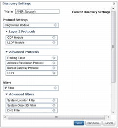
Create a New Discovery Profile
When we create the discovery profile, we are telling Cisco Prime Infrastructure which protocols we want to use from the ones mentioned above to discover the network. Each of them has its own pros and cons, but it's definitely necessary to have them all available at our discretion. Discovery can be easily accessed from the Getting Started Wizard when you log in for the first time or by navigating to Operate > Discovery (under Device Work Center). There are two options here: Quick Discovery and Discovery Settings. Quick Discovery allows you mainly to ping sweep your network followed by SNMP polling to get more details on the devices.
If you are planning to configure the discovery correctly the first time and reuse your configuration, start by clicking Discovery Settings. Now click New in the discovery settings modal pop-up. A window (as shown above) will pop up, where you can configure all the discovery settings will open. You will observe that the pop-up is broken down into multiple sections: Protocol Settings, Filters, Credential Settings, and Preferred Management IP (only two are shown in the preceding figure). You need to select at least one item from Protocol Settings, SNMP and Telnet/SSH from Credential Settings, and Preferred Management IP.
Start by giving the profile a suitable name. Depending on how many protocols you want to enable, start filling in the relevant information. Click the "+" icon next to the Ping Sweep Module to open up more settings. You can add your subnets manually or use the Import CSV File button to import all your subnets from a simple CSV file. The CSV file needed for the import will have columns that correspond to the GUI, such as IP Address and Subnet Mask. Similarly you can fill in more protocols as well, but remember that the more protocols you add, the more time it will take to converge the discovery.
TIP: If the majority of your devices are Cisco, or if LLDP is enabled on Cisco/non-Cisco devices, then using Cisco Discovery Protocol/LLDP will converge the discovery faster. If the network has a mixture of multivendor network devices, ping sweep should help. Ping sweep will also help with doing a directed discovery, for example, on a 10.1.1.0/24 network.
TIP: If Cisco Discovery Protocol information is desired in the Device Work Center, Cisco Discovery Protocol can be enabled in the discovery. It is not mandatory.
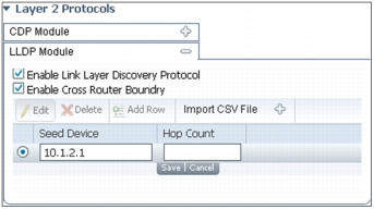
Configuring Cisco Discovery Protocol/LLDP
Configuring Cisco Discovery Protocol and configuring LLDP are very similar in nature. The first check box enables the use of LLDP in the discovery. The second check box enables jumping the router (or Layer 3) boundaries. Cisco Discovery Protocol is a Layer 2 protocol, and if we want the discovery to continue all the way until there are no neighbors available, we need to use this option. Unlike ping sweep, the seed device for a Cisco Discovery Protocol/LLDP discovery is a single device from which the discovery should initiate. If the hop count is left blank, discovery will continue until the end of the Cisco Discovery Protocol/LLDP neighbor is reached. You can add your subnets manually or use the Import CSV File button to import all of your Cisco Discovery Protocol/LLDP seeds from a simple CSV file. The CSV file needed for the import will have columns that correspond to the GUI, such as Seed Device IP Address and Hop Count.
Other protocols are very similar in nature. Some require the hop counts, while others like Border Gateway Protocol (BGP) and OSFP don't require hop counts.
Filtering
If you want to discover all of the subnets but would like to have a way to import information on certain devices based on their IP address, system location, type of device, or DNS, you can use filters to do just that.
TIP: If you are running discovery for the first time, pick a smaller range or hop count to begin with. Do not use filters in this discovery. Once the results are what you expect, go back and edit that profile to add filters as needed.
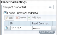
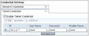
Credentials
Credentials are also an important part of the discovery. Please refer to the credential matrix from the Protocol Check section and enter the credentials appropriately. If this is not done, devices in the Device Work Center will error out with "Managing with Credential Errors." You can configure multiple community strings for the same network. This really helps to manage multiple devices without having to worry about which community is configured on what device.
For example, in the figure above, you could add another SNMP string for the 10.1.2.* network in addition to the one already configured.
The last thing to configure before we run discovery is the preferred management IP. Once the devices are discovered and added to the inventory, how do you want to manage them? Do you want to see the device list with DNS, loopback IP, or local hostname configured on the devices (also called sysName)? If DNS is not used on your network devices, go ahead and select sysName. If devices have a specific management VLAN and all the devices have loopback configured for that, it would be a good idea to use that. DNS is the last choice as the device names become very long and it clutters up the device selector.
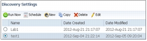
Discover the Network
With Cisco Prime Infrastructure, you can now discover the wired and wireless network in just one discovery. When the discovery profile is saved, select the discovery profile and click the Run Now button as shown in the figure on the left. The results will be displayed on the same page as the discovery settings. You can refresh the job and watch the status of the discovery in real time.
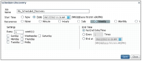
Scheduling Ongoing Discovery
In addition to running discovery in real time, you can schedule discovery to run when you want it. Select the discovery profile name and click Schedule instead of Run Now. You will get a modal pop-up that looks like the figure (above). Scheduling is extremely flexible in Cisco Prime Infrastructure. You can run every x minutes to y years.
Validate Discovery
Now that we have discovered our wired/wireless network, how can we make sure we are archiving the entire inventory, configuration, and other relevant information? We can start with inventory, as that is where we will know whether Cisco Prime Infrastructure was having issues fetching inventory or configuration information.
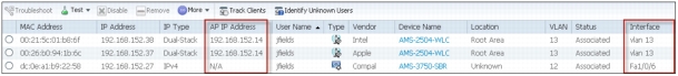
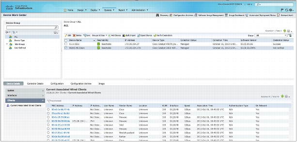
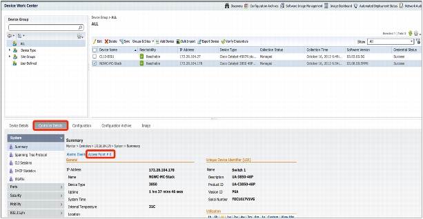
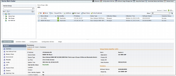
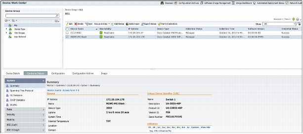
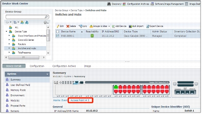
Device Work Center
Navigate to Operate > Device Work Center to see the entire inventory that has been discovered. The left pane allows you to filter on devices based on the device types or user-defined group that we can create. The top portion of the Device Work Center allows you to see quick information on the device as shown in the figure above. Once you click the device's name, the bottom pane is populated with more detailed information. Tabs in the bottom pane can be changed to quickly access focused, detailed information as seen in the image above.
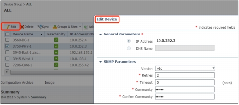
Fixing Credential Errors
At times you will encounter a few devices that don't have the SNMP strings or the CLI access that you thought they would have. You can either streamline or change the information on the devices, or if you have another set of credentials for a different subnet, you could add that to the CLI section of the discovery profile and rerun the discovery. If you have a handful of changes, you can click the devices with a status of Managed with Warning and then click the Edit button to modify the credentials.
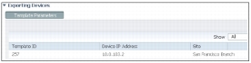
With Cisco Prime Infrastructure 2.0, there is now an ability to export devices with credentials directly from the GUI. Navigate to Operate > Device Work Center and you should be able to see the "Export Device" button as shown in following figure:
At that point in time, you can export the device credentials, change them using a spreadsheet application, and import them back.
TIP: If you need to change the credentials for devices in bulk, this method can be used to do that.
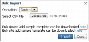
Importing Devices Manually
If you maintain a spreadsheet that has all the devices and would rather get started with that, you do have this option in Cisco Prime Infrastructure 2.0. If you to go Operate > Device Work Center > Bulk Import, you get an import pop-up as shown in the figure at the right.
TIP: Export the device template using the first "here" link. Use the exported CSV file to populate the device information. This will make sure your import goes through successfully.
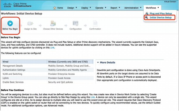
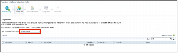
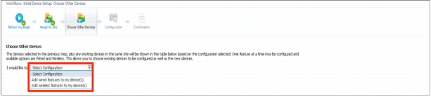
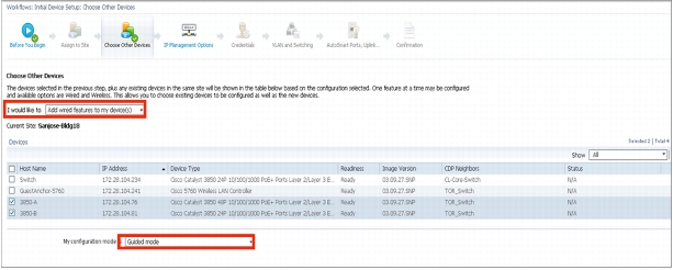
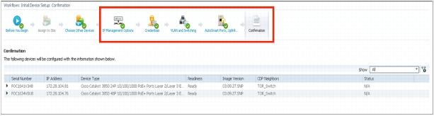
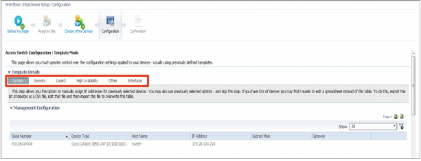
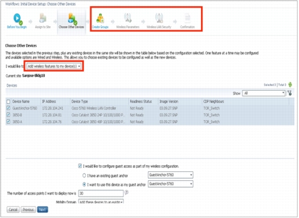
Automating Branch Device Deployment
If you have a need to deploy devices in branches from time to time, automated branch deployment can really ease your Day-0 task, by empowering you with zero-touch deployment. This is another way of automatically adding devices in Cisco Prime Infrastructure. There are some guided workflows as well to onboard newer 3850 switches and 5760 controllers. We will talk about this method in detail in "Advance Configuration Topics."
Deploying Wireless and Advanced Instrumentation
Cisco Prime Infrastructure can really simplify the dreaded task of deploying advance instrumentation like Application Visibility and Control (AVC), Flexible NetFlow, Next Generation Network Based Application Recognition 2 (NBAR2), and much more. Cisco Prime Infrastructure uses converged configuration templates to achieve this task. This section will focus on instrumentation that will help visualize some of the common challenges in managing application responses within a corporation.
Deploy a WLAN Using a Configuration Template
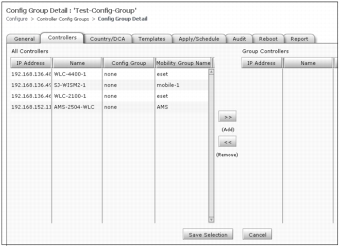
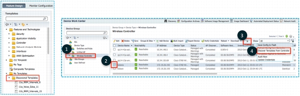
Configuration groups are an easy way to group controllers logically. This feature provides a way to manage controllers with similar configurations. Templates can be extracted from existing controllers to provision new controllers or existing controllers with additional configuration parameters. Configuration groups can also be used to schedule configuration sets from being provisioned. Controller reboots can also be scheduled or cascaded depending on operational requirements. Mobility groups, dynamic channel assignment (DCA), and controller configuration auditing can also be managed using configuration groups.
Configuration groups are used when grouping sites together for easier management (mobility groups, DCA, and regulatory domain settings) and for scheduling remote configuration changes. Configuration groups can be accessed from Design > Wireless Configuration (under Configuration) > Controller Config Groups.
• Adding controllers: Controllers in WCS are presented and can be moved over to the new configuration group.
• Applying templates: Discovered or already present templates can then be applied to the controller.
• Auditing: Make sure that template-based audit is selected in the audit settings and then audit the controllers in the group to make sure that they comply with policies.
NetFlow
NetFlow is an embedded instrumentation within Cisco IOS Software to characterize network operation. Visibility into the network is an indispensable tool for IT professionals. NetFlow gives network managers a detailed view of application flows on the network. Cisco Prime Infrastructure supports Traditional NetFlow (TNF) as well as Flexible NetFlow (FNF). A summarized view of what versions of NetFlow exist, their support, and their implied usage in Cisco Prime Infrastructure can be seen in the following two tables.
Flow Record Type
NetFlow Version
Cisco Prime Infrastructure Support
Template to Use
Technologies Used By
Traditional NetFlow (TNF)
Cisco
(v5)
Yes
There is no template for this, but one can be created.
• Network traffic stats
Flexible NetFlow (FNF)
RFC 3954
(v9)
Yes
Collecting Traffic Statistics under OOTB (Out of the box) Folder
• PerfMon
• Performance Agent (PA)
IPFIX
RFC 5101
RFC 5102
(v10)
Yes
AVC Template uses IPFIX
IPFIX is a protocol developed by the IETF working group. The IETF Working group used NetFlow v9 as the basis for IPFIX.
The following table shows further breakdown of NetFlow, and how NetFlow data is used for application visibility.
Features
Description
Export Format Support
Template to Be Used
Suggested Use
TNF
Basic NetFlow records
Version 5
Custom template needs to be created
Old platform that does not support Flexible NetFlow or IPFIX yet.
FNF
Flexible, extensible flow records. Report application from NBAR2.
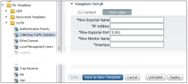
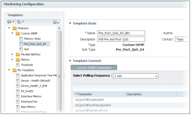
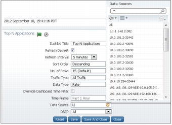
Deploying TNF is relatively simple, but FNF can be challenging. Cisco Prime Infrastructure greatly simplifies managing NetFlow end to end. You can follow the design, deploy, operate, report model for NetFlow as well. You can design the NetFlow template by going to Design > Configuration Templates > My Templates > OOTB > Collecting Traffic Statistics. This will open the NetFlow v9 templates as shown in the figure above. You can fill in all the metadata at the top of the template and save as a new template.
The next step is to publish the template so that it becomes available for other members to deploy the template. Note that the default port for NetFlow for Cisco Prime Infrastructure 2.0 is 9991 and cannot be changed in this release.
TIP:Samplicator (Not tested nor supported by TAC) may be used to point all devices to send NetFlow to one place. Samplicator can then fork out NetFlow data to multiple Cisco Prime Infrastructure instances as desired. Samplicator can also be used for syslogs and traps in addition to Netflow.
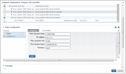
Now that the template is published, the next task is to deploy the template so that we can configure devices to start sending NetFlow data to Cisco Prime Infrastructure. Go to Deploy > Configuration Templates, find Collecting Traffic Statistics in the list, and click Deploy.
You will see the Template Deployment modal pop-up window (see figure above). Select the device or devices, fill in the values, and click Apply to accept the changes. You can fill in values for each device or you can use the export to/import from a spreadsheet option for quick data entry. Click the CLI Properties to see the CLI that is generated from the values provided. Finally, schedule your job to enable NetFlow on the devices.
Check Whether NetFlow Data Are Coming or Not
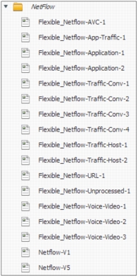
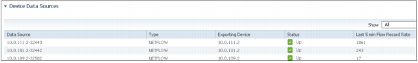
We have now enabled NetFlow on the devices, but how do we know whether or not Cisco Prime Infrastructure is receiving it? A quick way to tell is to go to Design > Monitor Configuration and see if there are multiple NetFlow instances for each unique NetFlow template. Normally you will see a template (see figure on left) as Flexible_NetFlow-<FNF_Type>. Once you click that template, the right pane will show template details. The bottom most portion (see figure above), Exporting Devices, should tell us which device is using/sending the NetFlow for that template. The middle portion of the same template shows all the attributes sent in that template. You may also run a report by choosing Report > Report Launch Pad > Raw NetFlow Reports and selecting a netFlow report. Click New to generate a new report. Specify all the details and run the report to see if you are really getting any data from this device based on what was configured. All NetFlow-pertinent dashlets will also start populating automatically (after two polling cycles).
Medianet
The Cisco architecture for medianet is an end-to-end IP architecture that enables pervasive and quality rich-media experiences. Medianet combines a smarter network to smarter endpoints with medianet technology embedded into network elements and endpoints. Cisco Prime Infrastructure simplifies the whole lifecycle for medianet from enablement to reporting.
Enabling Medianet
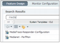
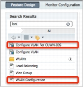
Enabling medianet does require using the CLI to configure some devices that support medianet. Cisco Prime Infrastructure has predefined templates for enabling medianet. Just as we enabled NetFlow, we can do the same thing for medianet. Navigate to Design > Feature Design > Search for "medianet", as shown in the figure (below).
The first one is to make a medianet device as medianet responder, while the last one is for enabling medianet PerfMon, which allows you to see the traffic that is flowing through a given interface. The steps for deploying the template remain the same as with any other CLI template. Note that the first two templates for enabling medianet do not have any variables.
TIP: Make sure that a user is defined in the device with privilege level 15 for the Web Services Management Agent (WSMA) to work.
Check Whether Medianet Is Enabled
Once medianet is turned on, there are a few commands that can be executed on the CLI to see whether the devices can show the medianet data. Here are a few commands you can use on the devices:
show mediatrace session statistics
show mediatrace session data
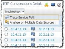
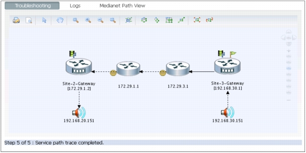
Please refer to the Troubleshooting Guide for details on how to make sure medianet is operational. Once medianet is verified to be working, we can see the RTP conversation (see the figure above) details dashlets showing sessions.
For troubleshooting, simply choose Troubleshoot > Trace Service Path in the same dashlet. This will launch another window where Mediatrace can be visually seen as in the figure above.
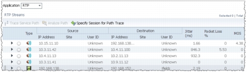
To see the active calls navigate to Operations > Path Trace under Operational Tools. You can then select the audio or video calls with jitter/packet loss for troubleshooting as shown in the figure above.
Monitoring/Troubleshooting
Basic Monitoring
Cisco Prime Infrastructure provides a very easy and flexible model for monitoring your wired/wireless network. Cisco Prime Infrastructure allows you to define or "design" monitoring templates that dictate how and what you want to monitor. You can then turn on monitoring by deploying the monitoring template. The results are then shown in the form of dashboards, dashlets, and reports.
Basic Device Health
The Basic Device Health feature is turned on by default for all devices. This includes device monitoring of device availability, CPU, and memory. Basic Device Health is polled every 5 minutes by default, but you can customize this as well.
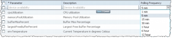
The template is called Device Health - choose Design > Monitoring Configuration > Features > Metrics > Device Health. The parameters can be changed by clicking the polling value for that row as shown in the figure below.
TIP: Don't forget to save the template after making the changes. The template will need to be republished and redeployed if changes are made.
Interface Statistics
Interface Statistics are not enabled by default, as monitoring interfaces can get very tricky if not done correctly. Some business-critical device interfaces should be polled more often than others, so there is no "one size fits all" when it comes to monitoring interfaces. Interface polling can be very quickly enabled by using a predefined monitoring template. You can navigate to Design > Monitoring Configuration > Features > Metrics > Interface Health (shown below). Follow the same methodology to change the polling interval as mentioned for Device Health. You can see how interface availability is changed to every minute.
Design Custom Monitoring Templates
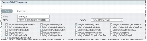
Flexible monitoring templates enable users to customize how they monitor their network. You can create your own templates by navigating to Design > Custom SNMP Templates and selecting the MIB and the table as shown in the figure on the left. You can then see all the variables from the table. Select the ones you are interested in, and they will be now available for polling. If the MIB you are interested in is not available in the drop-down list, you can upload a new MIB by clicking Upload MIB on the same page. Once you save the page after selecting the object identifiers (OIDs), you should see a template created as shown in the figure below
You can now create a poller from this template. If you now change the metadata and save this template, it will become a deployable monitoring poller and will be visible under My Templates. You are now ready to deploy the template to get monitoring started.
Deploy Custom Monitoring Templates
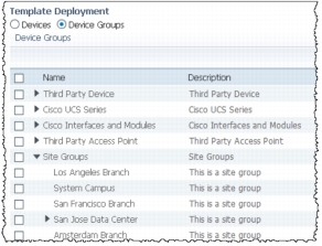
In order to deploy the monitoring template just created, you can navigate to Deploy > Monitoring Deployment > My Templates. Table view allows users to see how many devices are being polled using the template in question. Now locate your template, select it, and click Deploy. You will see a modal pop-up list as shown in the figure at the left. You can either select a device or devices or you can select the Device Groups option to select predefined or user-defined groups or even sites, as shown in the figure at left. Choose the appropriate group, and click Submit. Once back in Table view, you can see that devices are now assigned to the poller we chose in the previous step. This means that Cisco Prime Infrastructure will now be polling the devices based on what was designed in the template.
Data Collection from NAM
In order for Cisco Prime Infrastructure to manage Network Analysis Module, it needs to have a minimum software version of 5.1.1 plus the latest patches available.
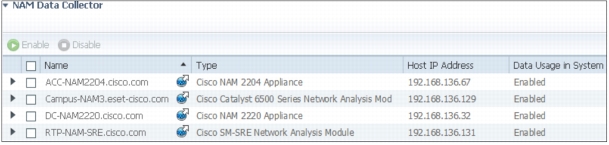
We can then make sure that Cisco Prime Infrastructure is enabled to poll the NAM data. You can navigate to Administration > Data Sources (Under System Setting SubMenu). The top portion of the same page shows all the devices that are actively sending NetFlow data to Cisco Prime Infrastructure. The bottom pane of the page shows all the NAMs that have been discovered or added to the inventory.
Select the NAM that should be polled by Cisco Prime Infrastructure, and click Enable as shown in the figure below.
Turning on Advanced Monitoring
Cisco Prime Infrastructure consumes a lot of information from various different sources. Some of the sources for data include NAM, NetFlow, NBAR, medianet, PerfMon, and Performance Agent. Detailed description of these advance monitoring can also be referenced from AVC Solution Guide (http://www.cisco.com/en/US/prod/collateral/netmgtsw/ps6504/ps6528/ps12239/solution_overview_c22-728972.html#wp9000608) posted on Cisco.com. The following table depicts the sources of the data for the site dashlets as used by Cisco Prime Assurance:
Dashlet Category
Dashlet Name
NAM
Medianet
NetFlow
PA
NBAR2
Site
Application Usage Summary
y
y
y
y
y
Top N Application Groups
y
y
y
y
y
Top N Applications
y
y
y
y
y
Top N Applications with Most Alarms
y
y
y
y
y
Top N Clients (In and Out)
y
y
y
y
y
Top N VLANs
y
y
y
Worst N RTP Streams by Packet Loss
y
y
Worst N Clients by Transaction Time
y
y
The following table shows how the application-specific dashlets get populated in Cisco Prime Assurance:
Dashlet Category
Dashlet Name
NAM
Medianet
NetFlow
PA
NBAR2
Application
Application Configuration
y
y
y
y
y
Application ART Analysis
y
y
App Server Performance
y
y
Application Traffic Analysis
y
y
y
y
Top N Clients (In and Out)
y
y
Worst N Clients by Transaction Time
y
y
Worst N Sites by Transaction Time
y
y
KPI Metric Comparison
y
y
y
DSCP Classification
y
y
Number of Clients Over Time
y
y
Top Application Traffic Over Time
y
y
Top N Applications
y
y
y
Top N Clients (In and Out)
y
y
y
Average Packet Loss
y
y
Client Conversations
y
y
Client Traffic
y
y
IP Traffic Classification
y
y
Top N Applications
y
y
DSCP Classification
y
y
RTP Conversations Details
y
y
Top N RTP Streams
y
y
Voice Call Statistics
y
y
Worst N RTP Streams by Jitters
y
y
Worst N RTP Streams by MOS
y
Worst N Sites by MOS
y
Worst N Site to Site Connections by KPI
y
y
y
NetFlow
Once we have verified that NetFlow is enabled on devices and directed to Cisco Prime Infrastructure, we are now ready to turn on monitoring for NetFlow. Just as for Device and Interface Health, all it takes is provisioning the appropriate monitoring template and deploying it. You can start out by going to Design > Monitoring Configuration > Features > Flexible NetFlow, choosing the templates based on what was discussed in an earlier NetFlow section, filling out the appropriate details, and saving the template. The template will be instantiated with the new name as specified in the header under My Templates.
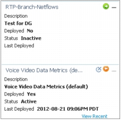
You can then navigate to Deploy > Monitoring Deployment. Look for the template you just created. In this case it's called "RTP-Branch-NetFlows". Looking at the figure on the right, templates with an orange ball with a right arrow are already deployed, and the templates with a green ball with a right arrow are the ones that are still not deployed. Once the template is deployed, dashlets should start populating the data after a couple of polling cycles.
WAN Optimization - Cisco Wide Area Application Services
Once you have deployed your WAAS changes at candidate sites, you can navigate to Operate > WAN Optimization to validate the return on your optimization investment. Cisco Prime Infrastructure also allows you to monitor WAAS-optimized WAN traffic by navigating to Operate > WAN Optimization > Multi-Segment Analysis. Click the Conversations tab to see individual client/server sessions, or the Site to Site tab to see aggregated site traffic. Some of the key dashlets to help with WAAS monitoring are detailed in the following table:
Dashlet
Description
Transaction Time (Client Experience)
Graphs average client transaction times (in milliseconds) for the past 24 hours, with separate lines for optimized traffic and pass-through traffic (in which optimization is turned off). With optimization enabled, you should see a drop in the optimized traffic time when compared to the pass-through time.
Average Concurrent Connections (Optimized versus Pass-through)
Graphs the average number of concurrent client and pass-through connections over a specified time period.
Traffic Volume and Compression Ratio
Graphs the bandwidth reduction ratio between the number of bytes before compression and the number of bytes after compression.
Multisegment Network Time (Client LAN-WAN - Server LAN)
Graphs the network time between the multiple segments.
Average and Maximum Transaction Time
The time between the client request and the final response packet from the server. Transaction time will vary with client uses and application types, as well as with network latency. Transaction time is a key indicator in monitoring client experiences and detecting application performance problems.
Average Client Network Time
The network time between a client and the local switch or router. In WAAS monitoring, client network time from a Wide Area Application Engine (WAE) client data source represents the network round-trip time (RTT) between the client and its edge WAE, while client network time from the WAE server data source represents the WAN RTT (between the edge and core WAEs).
Average WAN Network Time
The time across the WAN segment (between the edge routers at the client and server locations).
Average Server Network Time
The network time between a server and NAM probing point. In WAAS monitoring, server network time from a server data source represents the network time between the server and its core WAE.
Average Server Response Time
The average time it takes an application server to respond to a request. This is the time between the client request arriving at the server and the first response packet being returned by the server. Increases in the server response time usually indicate problems with application server resources, such as the CPU, memory, disk, or I/O.
Traffic Volume
The volume of bytes per second in each of the client, WAN, and server segments.
Average and Maximum Transaction Time
The time between the client request and the final response packet from the server. Transaction time will vary with client uses and application types, as well as with network latency. Transaction time is a key indicator in monitoring client experiences and detecting application performance problems.
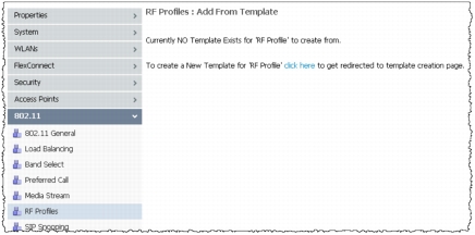
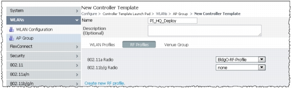
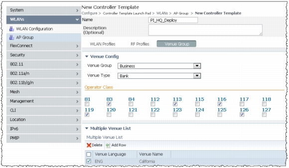
Monitor/Troubleshoot a Wireless Network
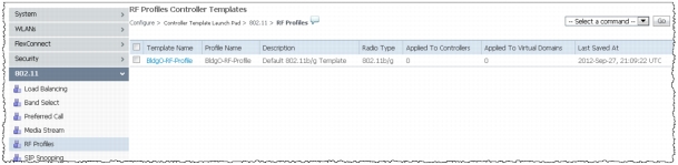
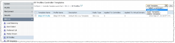
RRM/Clean Air
RF profiles and groups are supported in Cisco Prime Infrastructure for both RF profile creation templates and AP group templates. If you use Cisco Prime Infrastructure to create the RF profiles through the creation of templates, this gives the administrator a simple way to create and apply templates consistently to groups of controllers. The process flow is the same as was previously discussed in the controller feature set with some minor but important differences.
The process is the same as previously discussed in that you first create RF profiles, and then you apply the profiles through the AP groups. There are differences in how this is done from Cisco Prime Infrastructure and in the use of templates for deployment across the network.
Build RF Profile
With Cisco Prime Infrastructure there are two ways that you can approach building or managing an RF profile. Choose Configure > Controllers, then click the IP address of the controller and choose 802.11 > RF Profiles in order to access profiles for an individual controller.
The figure below displays all the RF profiles currently present on the chosen controller and allows you to make changes to profiles or AP group assignments. The same limitation as with the controller GUI is in effect in regard to a profile that is currently applied to an AP group. You have to disable the network or unassign the RF profile from the AP group.
When you create a new profile, Cisco Prime Infrastructure prompts you to choose an existing template. If this is the first time it is being accessed, you are directed to the Template Creation dialogue for an 802.11 controller template.
You may also navigate to Configure > Controller Template Launch Pad > 802.11 > RF Profiles (see figure on left) in order to go to the controller template launch pad directly.
In both cases, a new RF profile is created in Cisco Prime Infrastructure through the use of a template. This is a preferred method, since it allows the administrator to use the workflow of Cisco Prime Infrastructure and apply templates and configurations to all or select groups of controllers and reduce configuration errors and mismatches.
Complete these steps:
1. In order to create an RF profile template, choose Add Templates from the pull-down menu at the top right of the screen as shown in the figure at right.
2. Configuration of the template/settings is almost identical with the addition of a template name. Make this descriptive for easy recognition in the future. Change settings as needed or required and choose Save as seen in the figure below
Note: If you choose a threshold value for Transmit Power Control Version 2 (TPCv2) and it is not the chosen TPC algorithm for the RF group, then this value is ignored.
TIP: A simple setting to change for validation is the minimum TPC power. The minimum power can be raised if you choose a dBm value that is more than the current power level assigned by Radio Resource Management (RRM). This helps to validate the RF profiles operation.
3. Once you click Save the options at the bottom of the screen change as shown in the following figure (below):
Choose Apply to Controllers and the controller dialogue box appears to display the list of controllers managed by this server as shown in the figure below
4. From the figure on the right, Select Save Config to Flash box, then select the controller that you wish to have the profile available on, and click OK.
5. You can see the controller template results as shown in the figure below:
6. Now when you view the RF profiles screen, you can see the new template created as shown in the figure below.
The previous steps can be repeated in order to create and apply additional templates as required, for example, for 802.11b.
Apply RF Profiles to AP Groups
As with the WLC configuration for RF profiles, newly created profiles can be applied to a controller through the use of AP groups they are assigned to. In order to do this, either a previously saved AP group VLANs template or a newly created template can be used.
Choose Configure > Controller Template Launch Pad and choose AP Group as shown in the figure below.
In order to create a new template, choose New and fill in the required information. See the figure below.
Choose the RF Profiles tab in order to add RF profiles as shown in the figure (above).
In Cisco Prime Infrastructure 2.0, you can choose the Venue Group tab in order to add venue information as well. (See the figure above.)
If you save the template, a warning message may appear. As stated in the previous message, the change of the interface that the assigned WLAN uses disrupts the VLAN mappings for FlexConnect APs applied in this group. Ensure that the interface is the same before you proceed.
Once you choose OK, the dialogue is replaced with more options. Choose the Apply to Controllers option as shown in the following figure.
Choose the controllers to which the template needs to be applied as shown in the figure below.
Cisco Prime Infrastructure responds with operational status (see the figure below) on whether the template was successfully applied to the selected controllers.
If the template was not pushed successfully, NCS provides a message that states the reason for the failure. In this example, the RF profile that is applied to the group is not present on one of the controllers to which the template was applied.
Apply the RF profile again, specifically to that controller, and then reapply the AP group in order to generate a successful message.
Once the AP group has been deployed with the RF profiles applied (click the Apply to Access Points button), only access points attached to the controllers where the AP group was deployed successfully are available to select from.
Note: Until this point, no real changes were made to the RF infrastructure, but this changes when APs that contain new RF profiles are moved into the group. When an AP is moved into or out of an AP group, the AP reboots to reflect the new configuration.
Choose the APs you want to add to the AP group and choose OK. A warning message appears. NCS displays the status of the change.
Monitor/Troubleshoot Clients and Users
Client Visibility
In NCS 1.0, both wired and wireless monitoring and troubleshooting have been integrated with identity services. Integration between wired/wireless network management has been achieved through three network elements:
• Cisco Wireless LAN Controllers
• Cisco Catalyst® Switch security features: AAA, RADIUS, 802.1x and MAC authentication, MAC notification traps (nonidentity clients), syslog (identity clients only)
• Cisco Identity Services Engine (ISE)
All clients - wired and wireless - are displayed in the Clients and Users page (Monitor > Clients and Users).
Wired clients display AP name as N/A. Switch port information is provided in interfaces column as shown in the figure below.
Wireless Clients
In order to launch the client-troubleshooting tool, click the button to the left of the client list item. Once the client is selected, click the Troubleshoot icon in the toolbar, as shown in the following figure:
The following window is displayed for the client:
Log messages can be retrieved from the controller with the use of the Log Analysis tool, as shown in the following figure:
Refer to the Policy Enforcement Module (PEM) for more information on the PEM state.
The Event History tool provides users with event messages from clients and APs, as shown in the following figure:
Test Analysis Tool (CCXv5 Clients)
CCXv5 clients are client devices that support Cisco Compatible Extensions version 5 (CCXv5). You can now have troubleshooting capabilities for these clients in the Test Analysis section.
Wired Clients
Cisco Prime Infrastructure 2.0 provides integrated management of wired and wireless devices/clients. Cisco Prime Infrastructure 2.0 also provides monitoring and troubleshooting for wired and wireless clients. SNMP is used to discover clients and collect client data. ISE is polled periodically to collect client statistics and other attributes to populate related dashboard components and reports.
If ISE is added to the systems and devices are authenticating to it, the Client Details page displays additional details labeled as Security within the Client Troubleshooting, as shown in the following figure:
In order to navigate to Operation > Clients and Users, select a client, and click the Troubleshoot icon on the tools menu at the top of the page, as shown in the following figure:
This takes the user to the page shown in the screen shot below. In this example, the client device has link connectivity, but failed IP connectivity.
On the right side of the screen, there is a tool bar with these items, all related to troubleshooting:
• Client Troubleshooting Tool
• Log Analysis
• Event History
• Context Aware History
Event History provides messages related to connectivity events for this client. In this example, the client failed to successfully authenticate. Date/time is provided to assist the network administrator in troubleshooting this client.
ISE provides authentication records to NCS through the REST API. Network administrators can choose a time period for retrieving authentication records from ISE. In the example in the following figure, the authentication record indicates that the user was not found in the ISE database.
Alarms and Events
Alarms and events provide a single page view of all alarms and events for wired and wireless infrastructure. Persistent alarm summary and alarm browser are displayed at the bottom right of the screen (the figure on the right) regardless of what screen the user is on. Next to it is the Alarm Browser view that shows all the alerts based on severity and device types as shown in the figure below.
Quick Filter
Almost all of the tables in Cisco Prime Infrastructure have a quick filter widget. This quickly allows users to filter through the table, especially when there are many rows involved. This is very useful with alarms and events or clients and users. The figure (below) shows how quickly correct alarms can be filtered with this.
Creating Advanced Filter
The Advanced Filter, as the name implies, allows user to filter on the content with complex rules. The following figure shows the Advanced Filter being used with more complex rules. These filters can be saved for one-click use the next time they are needed.
Trigger Packet Capture from Cisco Prime Infrastructure
Cisco Prime Infrastructure provides a very flexible solution for capturing packets throughout your network. You can either manually trigger a packet capture or automatically specify the capture based on some advanced parameters, so that it will be triggered once a threshold level is breached. In both of these solutions, packets can be captured locally on the NAM or they can be stitched from multiple NAMs and stored in Cisco Prime Infrastructure.
Manual Packet Capture from Cisco Prime Infrastructure
In order to do an ad hoc packet capture, you can navigate to Operate > Packet Capture (under Operational Tools) > Capture Sessions. If you are coming to this page for the first time, you may not have any capture profiles set up. In order to create a new profile, click Create and fill in all the criteria for capturing a particular traffic. If you have a need to capture a particular type of traffic all the time, it may a good idea to proactively create those profiles and test them out before automating them, as will be shown in the next section.
Once the profile is defined, you can test it out by clicking Start, as shown in the preceding figure. See if the packets are captured correctly. You can then use these profiles for automatically capturing packets.
Automating Packet Capture Using Cisco Prime Infrastructure
There are times when you want to capture packets based on a trigger. There is no way to find out ahead of time when the trigger will happen. For example, if you are trying to meet the SLA for AvgRespTime for an application, you may want to start the packet capture if the response time exceeds the predefined time. You can easily achieve this by combining threshold and packet capture in Cisco Prime Infrastructure. Navigate to Design > Monitoring Configuration > Features > Thresholds. When you click a threshold template, you can create a new instance from it. Besides the header information, you can select thresholds based on your interest from Traffic Analysis, Application, Voice/Video Signaling, Voice/Video Data, Interface Health, Device Health, and NAM Health. It would be a good idea to explore these options and see what types of trigger points each of them has. Once you select the category for capture, you can then select the subcategory. All the trigger points can then be seen. In order to change any of them, simply select that row and edit the threshold as shown in the image above. You can see (figure above) that we have chosen to alert and start capturing Sharepoint traffic if the AvgRespTime exceeds the default value.
Decoding Packet Capture Using Cisco Prime Infrastructure
Once the packets are captured, there are two options to decode the capture. The easiest way is to select the packet capture session and click Decode from the Packet Capture homepage (Operate > Packet Capture). The capture decode is shown in a pop-up window, which makes it extremely easy to evaluate each and every packet as shown in the figure below.
You could also click the Export button and the .pcap file will be downloaded directly on the client PC. This is useful if you need to perform advance troubleshooting on the capture decode. There is a dimmed Merge button between the Decode button and the Export button, which can be used to merge the .pcap files if more than one file is selected.
TIP:If the capture file is not very large (that is, not on the order of GB), it makes sense to decode it in Cisco Prime Infrastructure instead of jumping over to the NAM. Otherwise, you should use NAM instead of Cisco Prime Infrastructure for decoding very large capture files.
Miscellaneous Multi-NAM Capabilities Within Cisco Prime Infrastructure
Cisco Prime Infrastructure can serve as a central manager of managers (MoM) if multiple NAMs are deployed in the network. Some of the functionality that Cisco Prime Infrastructure can help with includes:
• Centralized monitoring of NAM health
• Deploying configurations to multiple NAMs using the CLI configuration templates
• Upgrading NAMs using software image management capabilities
• Using one-click packet capture from multiple NAMs based on a capture policy
• Proactively capturing packets using threshold breaches
All of these allow users to use Cisco Prime Infrastructure to effectively manage the NAMs, thus making it a very good and stable data source for application visibility.
Remediate Issues
Remediate Wireless Issues
The following tools available within Cisco Prime Infrastructure may be used in order to remediate wireless issues:
• Cisco CleanAir®
• Client Troubleshooting
• AP Troubleshooting
• Audit Tool
• Security Dashboard
• Switchport Tracing (SPT)
• Apart from these key tools, you can find more tools by navigating to Operate > Wireless (under Operational Tools).
• Contextual device 360-degree views for easy access to assorted tools:
– Ping
– TraceRoute
– Cisco Discovery Protocol Neighbors
– WLAN and SSID information
– Active AP and client count
Remediate Wired Issues
The following tools within Cisco Prime Infrastructure can be used to remediate wired issues:
• Wired Client Troubleshooting
• Ad Hoc and Automated Packet Capture
• Device Work Center
• Contextual device 360-degree views for easy access to assorted tools:
– Ping
– TraceRoute
– Cisco Discovery Protocol Neighbors
– Config Diffs
– Inventory Details
– Network Audits
– Support Forums
Optimize
Use Cisco Prime Infrastructure to Optimize the Operation of Your Converged Network
There are several tools availabe within Cisco Prime Infrastructure to optimize your network.
Some of the tools that help optimize wireless infrastructure would be:
• Wireless Network Performance (RRM)
• Wired Performance (WAN bandwidth)
• Reports
Dashboard Customization
Cisco Prime Infrastructure uses the latest dashboard, which uses the latest technology of CSS3, HTML5, as well as AJAX with some charts. All of these allow for easy customization and visualization of data. There two main ways of customizing the dashboards:
• Adding your own dashboard in addition to the ones provided
• Adding/moving dashlets (aka portlets) from one dashboard to another
First navigate to one of the four existing dashboards as show in the figure above.
You can easily add a new dashboard by going to the top right of the screen and clicking the Edit Dashboard () icon. You should see a new pop-up as shown in the figure at the right. Depending on where you were in the menu when you clicked the gear icon, a new dashboard will be created under that tree. Type in a suitable name for the dashboard and click the Add button to create a new dashboard. A new tab is reflected immediately. If you created a tab by mistake, you can simply go to Manage Dashboards as shown in the figure at the left and delete the newly created dashboard, and then re-create a new one under the appropriate dashboard.
Note that Add/Remove Filter(s) applies only to the default dashboards and not for the custom dashboards. By default all of these filters will be populated for the default dashboards.
The next step is to populate the new dashboard that you created with content. This is done by adding dashlets to it. There are about 50 preconfigured templates that you can use for various dashboards.
A new dashlet can be added by going to the dashboard where you want it to show up and clicking Add Dashlet(s) from the Edit Dashboard menu. Once you see the list of dashlets, you can simply drag and drop the desired dashlet onto the dashboard. You should see a green bar as a confirmation that the dashlet will stay there, as shown in the figure below
Customizing the Dashlet Content
We can not only customize the dashboard but also the content within the dashlets. At times, you may want to know the rates instead of the volume, or you may want information coming from NetFlow instead of NAM or vice versa. You can configure the dashlet to show just that. First, make sure the needed dashlet already exists in the dashboard. If not, you will need to create it as shown in the previous section. Now click Dashlet Options, as shown in the figure (below).
This will expose all of the configurations that can be tweaked for a given dashlet as shown in the figure (right). You may now use the pull-down menu to select and configure as needed. Some key interesting things to note are data type, traffic type, data sources, and differentiated services code point (DSCP). Each dashlet will have its configuration parameters. Once you are done, click Save and Close to return to the default data view.
Advance Configuration Topics
Identity Services Engine Integration
Cisco ISE is a next-generation identity and policy-based network access platform that helps enable enterprises to enforce compliance, enhance infrastructure security, and streamline their service operations. See the figure above. Cisco Prime Infrastructure manages the wired and the wireless clients in the network. When Cisco ISE is used as a RADIUS server to authenticate clients, Cisco Prime Infrastructure collects additional information about these clients from the ISE and provides all relevant client information to Cisco Prime Infrastructure to be visible in a single console.
Cisco Prime Infrastructure can be integrated with ISE by navigating to Design > External Management Servers (under Management Tools) > ISE Servers. You can add a new ISE server by selecting Add Identity Services Engine as shown in the figure above. You will then be prompted for some basic ISE connectivity information (see the figure at left above). Once that is entered, the ISE server is then added to the list. Most of the remaining configuration will need to be done on the ISE itself.
TIP: ISE has a locking mechanism if the password is entered incorrectly three times in a row. It is extremely important to use the correct credentials when integrating within Cisco Prime Infrastructure; otherwise the ISE web interface will be locked out. Users will then need to log in through the ISE CLI to unlock the web interface.
See "Understanding the Cisco ISE Network Deployment" for detailed ISE configuration tasks that are needed to populate the data consumed by Cisco Prime Infrastructure (the steps are the same as with NCS 1.1/ISE 1.x integration).
Automated Deployment
Automated deployment is a feature that started with Cisco Prime Infrastructure 1.2.1 that eases the pain of deploying new branch routers or switches. With Cisco Prime Infrastructure 2.0, the plug and play gateway is now built into the product itself. This method of provisioning is mainly targeted for branch routers. Normally when a device is provisioned in a new branch or remote site, it needs to be prepared for provisioning. Some network engineers prefer to stage the device completely and ship it to the end location, while others prefer to do a partial staging of the device so that it can come online once it's deployed in the end location. Management systems can then be used to push the full configuration. In both cases, a lot of manual configuration is needed, and it amounts to big delays in deploying a new branch or site.
Automated deployment could be used for places where quick and zero-touch deployments are desired. If a nontechnical staff is deploying the device in a remote branch, this feature will definitely prove to be useful.
Managing Converged Access Using Cisco Prime Infrastructure 2.0
Converged Access is the convergence of wired and wireless networks into a unified infrastructure. Cisco is also extending wired infrastructure concepts, features, resiliency, and scalability to the wireless infrastructure. Cisco Converged Access is composed of the following core products:
• The new Cisco Catalyst®3850 Series Switch with integrated wired and wireless functionality through built-in Cisco IOS Software wireless LAN controller (WLC), the new Unified Access Data Plane (UADP) application-specific integrated circuit (ASIC), and enhanced hardware and operating system.
• The new Cisco IOS Software-based Cisco 5760 WLC as appliance.
• The Cisco Catalyst 6500 Series Wireless Services Module 2 (WiSM2) or Cisco 5508 WLC (available through a software patch in the future).
Starting Cisco Prime Infrastructure 2.0, you can now manage converged access architecture in a simplified manner. This section will go into managing the converged access environment using Cisco Prime Infrastructure 2.0.
TIP: Before you jump into managing the 3850 switch using Cisco Prime Infrastructure, make sure the following steps are done:
• Make sure the Converged Access devices have a minimum of Cisco IOS-XE 3.2.2 or later running on them.
At a high level, following are the tasks that users will need to do in order to deploy converged access architecture using Cisco Prime Infrastructure 2.0:
Step 1. Set up a mobility domain and its hierarchies for the new mobility architecture
Step 2. Create VLANs and WLANs for the new mobility architecture
Step 1 - Setting Up a New Mobility Hierarchy Using Mobility Work Center
Mobility Work Center is a new feature within Cisco Prime Infrastructure 2.0, which eases management of Unified Access Switches/Controllers. You can navigate to Operate > Mobility Work Center to get started with creating components within new mobility architecture. This screen displays all the mobility devices that are being managed and their role in the Unified Network architecture (MA, MC, and MO). It is beyond the scope of the deployment guide to go into details of the new mobility architecture, but you can refer to the following web page on the topic to understand MA, MC and MO: http://www.cisco.com/en/US/netsol/ns1187/index.html.
For devices added to Cisco Prime Infrastructure, existing mobility domains and switch peer groups (SPGa) will be automatically populated in this screen.
TIP: Make sure you have atleast Cisco IOS-XE 3.2.2 running on 3850/5760 devices.
To create a new mobility domain, click the "Create Mobility Domain" button.
Users will be prompted to provide a mobility domain name and select devices to be members of the mobility domain.
Similarly, new switch peer groups can be created and devices added in Mobility Work Center.
Once you click on "Create", you can now add a new switch peer group as shown in figure below.
This creates automatic full-mesh mobility peering between controllers.
Step 2 - Create VLANs and WLANs for the New Mobility Architecture
There are two way of creating VLANs and WLANs for the new mobility architecture. If you are not familiar with the CLI commands for the new mobility architecture, it would be beneficial to use the wizard-based Guided Workflow GUI. Guided Workflow walks users in a step-by-step manner in configuring the new mobility architecture. It doesn't allow for advance customization, but you should be able to deploy basic mobility on converged access devices using a zero-touch deployment model.
Step 2a - Wizard-Based Guided Workflow for Creating VLANs and WLANs
Adding these converged access devices into Cisco Prime Infrastructure is the first place to start. While devices can be added or imported manually as mentioned earlier, it is easier to add them using the Plug and Play Setup (Day 0) guided workflow. This allows for managing a device without any need to console into the device (using the DHCP method). Once Cisco Prime Infrastructure knows the devices, we can run the Initial Device Setup (Day 1) guided workflow to add more wired and wireless related configuration. Plug and Play Setup (Day 0) and Initial Device Setup (Day 1) guided workflow (see the figure on right) are two independent workflows, hence devices discovered by any other means (manual, device discovery, import) can be configured by the initial device setup workflow as well.
In order to, add and configure devices using the Plug and Play Setup workflow, select Workflow > Plug and Play Setup.
TIP:
• TFTP should not be blocked in the network, as it is used by Cisco Prime Infrastructure to upload files to switches.
• Please use lifecycle view (as shown in figure below) for all configuration and template deployment operations for converged access devices, as classic view is not supported.
In the following figure you create a plug and play profile, which will be applied to ALL devices connected to Cisco Prime Infrastructure by this method. Configuration can be changed later.
Once the devices are in the Cisco Prime Infrastructure database, they can be configured using the Initial Device Setup (Day 1) guided workflow. This wizard will help configure devices discovered through Plug and Play Setup or other adding device mechanisms as mentioned earlier.
TIP: The wizard currently supports the Catalyst 2000, 3000, and 4000 Series switches, and 5760 controller.
Navigating to Workflows > Initial Device Setup will start the guided Initial Device Setup (Day 1) workflow wizard (see the following figure).
Devices are assigned to a site as shown in following figure (below).
TIP: Sites must be created ahead of time as mentioned in the earlier section "Creating Groupings and Sites."
Once assigned to a site (see the figure above), both wired and wireless features configuration can be initiated in the next screen (see the figure below).
In the Guided Mode, wired workflow enables users to configure IP management options, login credentials, VLAN(s), basic services, Cisco Discovery Protocol, Autosmart ports, and uplink(s). Autosmart ports can be enabled in the guided mode. Additional information about autosmart ports can be found in the reference section.
Follow through the wizard until the end where you have a chance to see the configuration before pushing it on the wire.
Wired Advanced Mode workflow is similar to the template configuration (see the figure below).
Wired Advanced Mode workflow enables users to configure system, security, HA, and the interface (see the figure below). It has an option to enter other CLI commands as well.
TIP: The uplink configuration is applied only on the identified/dedicated uplink ports on the switch. Downlink ports can't be configured with the uplink configuration.
Wireless Guided Mode workflow enables switch peer groups, mobility groups, wireless LAN, and security configurations. See the figure below.
Wireless workflow in Cisco Prime Infrastructure 2.0 supports 3850 switches and 5760 controllers. Following 3 modes are supported:
• Single MC mode with 3850 as the controller
• Single MC mode with 5760 controller
• Multi MC mode with 3850 as the controllers (exceeding 50 APs)
Step 2b - Creating VLANs and WLANs Using Templates (Advance Mode)
If you have a custom deployment scenario that cannot be met by a guided workflow, you may need to deploy new mobility architecture using some predefined configuration templates. You can use following two templates to deploy VLANs and WLANs:
VLANs -
Templates > CLI Templates > System Templates - CLI > Configure VLAN For CUWN-IOS
WLANs -
Templates > Features and Technologies > Controller > WLANs > WLAN Configuration
You can search for "lan" (see the figure on the left) to see all the applicable templates as mentioned above. You can go into any of the templates and deploy them based on what they do.
These two steps will allow you to deploy converged access devices using Cisco Prime Infrastructure.
Working with Converged Access Devices in Cisco Prime Infrastructure
TIP:
• In order to refresh complete configuration from converged access devices (3850 and 5760) to Cisco Prime Infrastructure, the recommended method is to use "Sync" from Device Work Center.
• When adding a 3850 and 5760, make sure that the SNMP Timeout value is at least 75 or more.
Wired clients connected through the selected switch/MA (Mobility Agent) can be viewed through Device > Detailed Details > Clients > Currently Associated Clients (see the figure below).
Wireless clients terminating the device can be viewed from the scope of the access point to which they are associated to. To view them, select Controller details and select the access point you want to view (see figure below).
Clicking on the Access Point link (see figure above) will take you to an access-point-centrered view. Selecting the access point allows you to view the wireless clients associated with it. (see figure below)
For devices where the configuration has been modified, Cisco Prime Infrastructure provides a way to view/compare configuration files with a side-by-side view of a running configuration and an archived configuration (for example, startup config). You can obtain this comparison at a device level through Operate > Device Work center > (Selected Device) > Configuration Archive (from the bottom pane).
TIP:You can alternatively access the information fromOperate > Configuration archives.
You can see a modal pop-up window showing the two configurations side-by-side. When you look at this initially, understand the significance of what each color means. See the following figure for a quick legend snapshot:
Discovering Templates from Converged Access Devices
For devices that have an existing configuration, templates can be discovered from the devices.
Template discovery from a device is initiated from the Device Work Center page using the following steps (see the figures below):
1. Select the Device Group. (See figure on left).
2. Select the device from the list view. (See figure above on right).
3. Click the double arrow from the menu bar. This will result in the Configure menu being displayed. (see figure at right)
4. Select Discover Templates from Controller from the drop-down menu.
Discovered templates will be listed under My Templates by navigating to Design > Feature Design. If you are trying to deploy template to one of the supported converged access devices, you need to select device type as "CUWN-IOS and UA" or "All" (wherever applicable) as shown in the figure on the left. If a template has the Device Type selection option "All" available and it is chosen, the same template can be deployed on both classical controllers (WLC) and supported converged access devices.
Monitoring Converged Access Switches
Converged access switches can also be monitored through the Device Work Center. The user experience is very similar. The device details tab (see the following figure) has however been augmented with switch specific information as well.
The controller details tab (seethe following figure) provides information about the wireless capabilities of the converged switch.
When monitoring a Catalyst 3850 switch, a list of APs that are joined to the switch can be displayed by clicking Access Point link from the controller detail page (see the following figure).
The converged access switch also provides 360-degree views. Launching the Device 360 View involves the same actions of clicking the bubble after the IP address (see the following figure).